

BOSCH REXROTH
R105704000
$86.11 USD
- BOSCH REXROTH
- Material:R105704000
- Model:SHAFT SUPPORT BLOC WBA-40-FO
Quantity in stock: 0
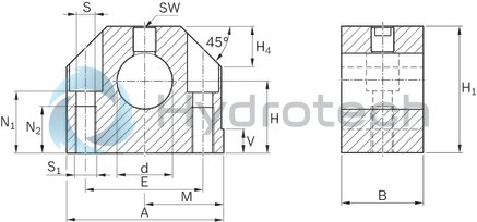
The Bosch Rexroth SHAFT SUPPORT BLOC WBA-40-FO (R105704000) is a high-quality aluminum shaft support block designed to provide rigid shaft mounting with its extra-wide design. This component features a topside clamping mechanism that enhances accessibility and ensures better security due to the larger thread diameter of the clamping screw. The product includes a drill hole for fastening from above, as well as a thread for securing from below, offering flexibility in mounting. With its precise design and reference edge, the WBA-40-FO allows for easy installation and quick alignment, streamlining the assembly process and ensuring accurate positioning. This attention to detail in design makes it more cost-effective compared to custom in-house designs. The product is part of Bosch Rexroth's linear guide accessories range and is specifically tailored to complement linear bushings and shafts. The shaft support block is manufactured from durable aluminum, ensuring longevity and resistance to wear under mechanical stress. Its dimensions are carefully crafted to fit specific requirements, with size specifications such as V, N, H, E, SW available upon consultation. The tightening torque values are also provided to ensure secure fastening without compromising the integrity of the structure. Overall, the Bosch Rexroth SHAFT SUPPORT BLOC WBA-40-FO (R105704000) stands out as a reliable accessory for linear motion applications that require precise shaft alignment and robust support. Its combination of thoughtful design features and sturdy construction makes it an essential component for various mechanical assemblies where precision linear movement is critical.
Shaft support block (aluminum), 40-FO
Shaft support block (aluminum)
Shaft diameter d = 40
Top securing
Unpacked Weight: 0.888 kg
| Material: Aluminum |
| Rigid shaft mounting due to extra-wide design |
| Topside clamping for better accessibility |
| Better security thanks to clamping screw with larger thread diameter |
| Thread for fastening from below |
| Drill hole for fastening from above |
| Reference edge for easy alignment |
| For easy installing and quick aligning |
| Precise design with reference edge |
| More affordable than in-house designs |
| Data Sheet | Download Data Sheet |
| 2D CAD | Download 2D CAD |
| 2D CAD | Download 2D CAD |
| 3D CAD | Download 3D CAD |
| 3D CAD | Download 3D CAD |
| Manual | Download Manual |
| Manual | Download Manual |
| Manual | Download Manual |
| Manual | Download Manual |
| Manual | Download Manual |
| Manual | Download Manual |
| Manual | Download Manual |
| Manual | Download Manual |
| Manual | Download Manual |
| Manual | Download Manual |
| Size V | 10 |
| Size A | 108 |
| Productgroup ID | 17 |
| Size N2 | 34 |
| Size H | 50 |
| Size E | 82 |
| Size SW | 6 |
| Size H4 | 28 |
| Size S | 13.5 |
| Tightening torque | 52 |
| Size N1 | 44 |
| Size d H8 | 40 |
| Shaft diameter d | 40 |
| Size M | 54 |
| Linear guide type | Linear bushing and shaft |
| Accessories for linear bushings | Shaft support blocks |
| Size B | 48 |
| Housing material | Aluminum = A |
| Weight | 0.888 |
| Size D1 with tolerance | |
| Size H1 | 88 |

|
Ød |
mm |
10 | 12 | 16 | 20 | 25 | 30 | 40 | 50 | 60 |
|
m |
kg |
0.05 | 0.06 | 0.11 | 0.18 | 0.35 | 0.48 | 0.9 | 1.5 | 3 |
|
MA |
Nm |
3.8 | 6.6 | 16 | 30 | 52 | 120 | 220 | ||
Legend
|
Symbol |
Description |
Unit |
|
Ød |
Shaft diameters |
mm |
|
m |
Mass |
kg |
|
MA |
Tightening torque |
Nm |
Abmessungen
|
Ød |
mm |
10 | 12 | 16 | 20 | 25 | 30 | 40 | 50 | 60 | |
|
A |
mm |
40 | 43 | 53 | 60 | 78 | 87 | 108 | 132 | 164 | |
|
B |
mm |
20 | 24 | 30 | 38 | 40 | 48 | 58 | 74 | ||
|
d |
H8 |
mm |
10 | 12 | 16 | 20 | 25 | 30 | 40 | 50 | 60 |
|
E |
27 mm ±0.15 | 30 mm ±0.15 | 38 mm ±0.15 | 42 mm ±0.15 | 56 mm ±0.15 | 64 mm ±0.15 | 82 mm ±0.15 | 100 mm ±0.2 | 124 mm ±0.2 | ||
|
H 1) |
18 mm ±0.01 | 20 mm ±0.01 | 25 mm ±0.01 | 30 mm ±0.01 | 35 mm ±0.01 | 40 mm ±0.01 | 50 mm ±0.01 | 60 mm ±0.01 | 75 mm ±0.01 | ||
|
H1 |
mm |
31 | 35 | 42 | 51 | 61 | 70 | 88 | 105 | 130 | |
|
H4 |
mm |
10 | 13 | 16 | 20 | 22 | 28 | 37 | 42 | ||
|
M 1) |
20 mm ±0.01 | 21.5 mm ±0.01 | 26.5 mm ±0.01 | 30 mm ±0.01 | 39 mm ±0.01 | 43.5 mm ±0.01 | 54 mm ±0.01 | 66 mm ±0.01 | 82 mm ±0.01 | ||
|
N1 |
mm |
14 | 16.5 | 21 | 25 | 30 | 34 | 44 | 49 | 59 | |
|
N2 |
mm |
13 | 18 | 22 | 26 | 34 | 42 | ||||
|
SW |
mm |
2.5 | 3 | 4 | 5 | 6 | 8 | 10 | |||
|
S 2) |
mm |
5.3 | 6.6 | 8.4 | 10.5 | 13.5 | 17.5 | 22 | |||
|
S1 |
M6 | M8 | M10 | M12 | M16 | M20 | M27 | ||||
|
V |
mm |
5 | 6.5 | 8 | 10 | 12 | 13 | ||||
| 1) | In relation to nominal shaft dimension "d" |
| 2) | Fixing screws ISO 4762-8.8 |