


BOSCH REXROTH
R103663020
$160.68 USD
- BOSCH REXROTH
- Material:R103663020
- Model:LSAE-A-30-DD
Quantity in stock: 0
The Bosch Rexroth LINEAR-SET LSAE-A-30-DD (R103663020) is a high-quality linear motion set designed for various applications requiring precise and smooth linear movement. The set includes an aluminum lightweight precision housing with a super linear bushing A, which features self-alignment capabilities, ensuring optimal performance even in misaligned installations. The shaft diameter 'd' is accompanied by two external seals that offer protection against contamination, thereby extending the service life of the unit. This linear set is adjustable and relubricatable, catering to maintenance requirements and providing flexibility in use. It boasts a standard version with remarkable dynamic load capacity C and static load rating C, which are critical for sustaining loads during operation. These capacities are specific to the main direction of loading; however, they can be adjusted with multiplication factors provided for non-main direction loads. The LINEAR-SET LSAE-A-30-DD operates efficiently within a permissible ambient temperature range and can handle maximum accelerations (amax) without compromising integrity. It also features an outer diameter D suitable for its size category H, along with a specified breakaway force necessary to initiate movement. The maximum permissible linear speed (vmax) indicates the swift motion capabilities of the set while maintaining its longevity, as evidenced by extensive travel tests without failure. Additionally, this model has been engineered to offer minimal frictional drag under no radial load conditions and comes pre-clamped to ensure zero-clearance or preloaded guides upon delivery. The adjusting screw included allows for easy radial clearance adjustments when required. With its weight optimized for balance between sturdiness and ease of handling, the Bosch Rexroth LINEAR-SET LSAE-A-30-DD proves to be an excellent choice for those in need of reliable linear motion solutions.
Linear set (aluminum), E-A-30, with two seals
Linear set (aluminum)
Adjustable
With super LB A
Shaft diameter d = 30
With two seals
Version: Standard
Unpacked Weight: 0.994 kg
For zero-clearance or preloaded guides. Adjusting screw for adjusting radial clearance. These Linear Sets come set to zero clearance.
| Lightweight precision housing (aluminum) |
| super linear bushing A with self-alignment feature |
| External seals |
| Relubricatable |
| Data Sheet | Download Data Sheet |
| 2D CAD | Download 2D CAD |
| 2D CAD | Download 2D CAD |
| 3D CAD | Download 3D CAD |
| 3D CAD | Download 3D CAD |
| Manual | Download Manual |
| Manual | Download Manual |
| Manual | Download Manual |
| Manual | Download Manual |
| Manual | Download Manual |
| Size V | 8 |
| Series | Super A (with self-alignment feature) |
| Footnote friction force FR | Frictional drags generated by linear bushings with integrated wiper seals on two sides when not under radial load. The frictional drags depend on speed and lubrication. |
| Size E1 | 68 |
| Footnote dynamic load capacity C | The load capacities apply for the main direction of loading. If the load direction is not the main direction of loading, the load capacities must be multiplied by the following factors: Ø d 10 to 16: ↩f = 0.82, f0 = 0.86 ↩Ø d 20 to 50: f = 0.82, f0 = 0.78 |
| Size H | 35 |
| Max. acceleration amax | 150 |
| Permissible ambient temperature | -10 °C ... +80 °C |
| Outer diameter D | 47 |
| Size H3 | 11.5 |
| Breakaway force | 6 |
| Size L3 | 16 |
| Size H4 | 22 |
| Maximum permissible linear speed vmax | 3 |
| Size D | 47 |
| Footnote static load capacity C0 | The load capacities apply for the main direction of loading. If the load direction is not the main direction of loading, the load capacities must be multiplied by the following factors: Ø d 10 to 16: ↩f = 0.82, f0 = 0.86 ↩Ø d 20 to 50: f = 0.82, f0 = 0.78 |
| Size N1 | 34 |
| Static load rating C0 | 3570 |
| Size M | 43.5 |
| Note: Maximum permissible speed vmax | Speeds of up to 5 m/s possible. Service life is limited by heightened wear to plastic parts. Tests have shown total travel from 50 • 105 m to 100 • 105 m without failure. |
| Friction force | 2.5 |
| Size A | 87 |
| Radial clearance | Comes clamped to h5 shaft (lower limit) and set to zero-clearance |
| Productgroup ID | 17 |
| Size N2 | 22 |
| Size E3 | 72 |
| Permissible ambient temperature (max) | |
| Size E2 | 45 |
| Size E4 | 30 |
| Size SW | 5 |
| Permissible ambient temperature (min) | |
| Size S | 8.4 |
| Shaft diameter d | 30 |
| Linear guide type | Linear bushing and shaft |
| Filter for linear bushings and shafts | Linear sets with linear bushings |
| Format of linear bushings | E – Adjustable |
| Dynamic load capacity C | 5860 |
| Size L | 79 |
| Size S2 | 6 |
| Weight | 0.994 |
| Size D1 with tolerance | |
| Size H1 | 70 |
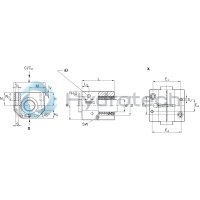
General technical data
|
Ø d |
mm |
10 | 12 | 16 | 20 | 25 | 30 | 40 | 50 |
|
amax |
m/s² |
150 | |||||||
|
vmax 1) |
m/s |
3 | |||||||
|
m |
kg |
0.1 | 0.13 | 0.2 | 0.34 | 0.65 | 0.97 | 1.8 | 3 |
|
FR 2) |
N |
0.5 | 0.8 | 1 | 1.5 | 2 | 2.5 | 3 | 4 |
|
Breakaway force |
N |
1 | 1.5 | 2 | 3 | 4.5 | 6 | 8 | 10 |
|
Radial clearance |
Comes clamped to h5 shaft (lower limit) and set to zero clearance | ||||||||
|
Operating conditions |
|||||||||
|
Permissible ambient temperature (min ... max) |
-10 °C ... +80 °C | ||||||||
| 1) | Speeds of up to 5 m/s possible. Service life is limited by heightened wear to plastic parts. Tests have shown total travel from 50 • 105 m to 100 • 105 m without failure. |
| 2) | Frictional drags generated by Linear Bushings with integrated wiper seals on two sides when not under radial load. The frictional drags depend on speed and lubrication. |
Load capacities and load moments
|
Ød |
mm |
10 | 12 | 16 | 20 | 25 | 30 | 40 | 50 |
|
C 1) |
N |
730 | 1020 | 1250 | 2470 | 4820 | 5860 | 10070 | 14730 |
|
C0 1) |
N |
380 | 490 | 620 | 1340 | 2790 | 3570 | 5570 | 8280 |
| 1) | The load ratings apply for the main direction of loading. If the load direction is not the main direction of loading, the load ratings must be multiplied by the following factors: Ø d 10 to 16: f = 0.82, f0 = 0.86 Ø d 20 to 50: f = 0.82, f0 = 0.78 |
| The load ratings are based on a total travel of 100, 00 m. When based on 50 000 m, the values in the table need to be multiplied by 1.26. |
Legend
|
Symbol |
Description |
Unit |
|
Ød |
Shaft diameters |
mm |
|
amax |
Maximum acceleration travel |
m/s2 |
|
C |
Dynamic load capacity |
N |
|
C0 |
Static load capacity |
N |
|
FR |
Friction force |
N |
|
m |
Mass |
kg |
|
vmax |
Maximum permissible speed |
m/s |
Impact of load direction on load rating of closed Linear Bushings
The listed load ratings should be chosen depending on installation in minimum or maximum position and should be based on the calculations. If the load direction is clearly defined and the Linear Bushings can be installed in maximum position, the load ratings Cmax. (dynamic load rating) and C0 max (static load rating) can be used. If aligned installation is not possible or the load direction is not defined, the minimum load ratings must be used.

Reduced load capacity with short stroke
In case of short stroke, the service life of the shaft is less than that of the super Linear Bushing. The load ratings C specified in the tables must therefore be multiplied by the factor f.s .
Reduced load capacity with high load
If the load F on a Super Linear Bushing A is more than F > 0.5 x C, the dynamic load rating C decreases.
Definition of dynamic load ratings
Self-alignment feature
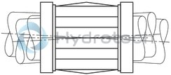
The self-alignment feature in the steel bearing plates and machined ball guide grooves ensure quieter travel. The flow chart shows a comparison with a conventional Linear Bushing. The example is based on a load of 800 N and misalignment of about 8 ft (caused by shaft deflection).
Due to the self-alignment feature, two super Linear Bushings must be used on at least one of the shafts in the guide.
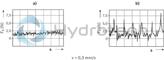
| FR = Frictional drag | |
| s = travel distance | |
| v = travel speed | |
| a) | Super Linear Bushing, A Ød 20 |
| b) | Conventional Linear Bushing, Ød 20 |
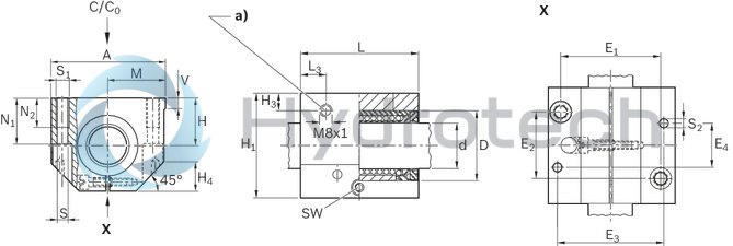
| a) | Lubricating hole sealed with plastic cap |
Dimensions
|
Ød |
mm |
10 | 12 | 16 | 20 | 25 | 30 | 40 | 50 |
|
D |
mm |
19 | 22 | 26 | 32 | 40 | 47 | 62 | 75 |
|
A |
mm |
40 | 43 | 53 | 60 | 78 | 87 | 108 | 132 |
|
E1 |
29 mm ±0.15 | 32 mm ±0.15 | 40 mm ±0.15 | 45 mm ±0.15 | 60 mm ±0.15 | 68 mm ±0.15 | 86 mm ±0.15 | 108 mm ±0.2 | |
|
E2 |
20 mm ±0.15 | 23 mm ±0.15 | 26 mm ±0.15 | 32 mm ±0.15 | 40 mm ±0.15 | 45 mm ±0.15 | 58 mm ±0.15 | 50 mm ±0.2 | |
|
E3 |
mm |
31 | 34 | 42 | 50 | 64 | 72 | 90 | 108 |
|
E4 |
mm |
29 | 32 | 35 | 45 | 20 | 30 | 35 | 42 |
|
H |
mm |
16 | 18 | 22 | 25 | 30 | 35 | 45 | 50 |
|
Tolerance for H 1) |
µm |
+ 8 - 16 |
|||||||
|
H1 |
mm |
31.5 | 35 | 42 | 50 | 60 | 70 | 90 | 105 |
|
H3 |
mm |
10 | 11.5 | 14 | 12.5 | ||||
|
H4 |
mm |
10 | 13 | 16 | 20 | 22 | 28 | 37 | |
|
L |
mm |
36 | 39 | 43 | 54 | 67 | 79 | 91 | 113 |
|
L3 |
mm |
10.5 | 11.5 | 13.5 | 15 | 16 | 18 | 22 | |
|
M 1) |
20 mm ±0.01 | 21.5 mm ±0.01 | 26.5 mm ±0.01 | 30 mm ±0.01 | 39 mm ±0.01 | 43.5 mm ±0.01 | 54 mm ±0.01 | 66 mm ±0.01 | |
|
N1 |
mm |
15 | 16.5 | 21 | 24 | 29 | 34 | 44 | 49 |
|
N2 |
mm |
11 | 13 | 18 | 22 | 26 | 34 | ||
|
S 2) |
mm |
4.3 | 5.3 | 6.6 | 8.4 | 10.5 | 13.5 | ||
|
S1 |
M5 | M6 | M8 | M10 | M12 | M16 | |||
|
S2 3) |
mm |
4 | 5 | 6 | 8 | 10 | |||
|
SW |
mm |
2.5 | 3 | 4 | 5 | 6 | 8 | ||
|
V |
mm |
5 | 6.5 | 8 | 10 | 12 | |||
| 1) | Clamped (fastened) in relation to Ø d. |
| 2) | Fixing screws ISO 4762-8.8 |
| 3) | Pin hole centering. |
Radial clearance
The radial clearance values shown in the table have been determined from statistics and correspond to values expected in practice. The adjustable Linear Sets come clamped to an h5 shaft (lower limit) and set to zero clearance.
Vertical dimension
The tolerance values for the vertical dimension "H" for the Linear Sets shown in the table have been determined from statistics and correspond to values expected in practice.
Bolts
We recommend bolts in accordance with ISO 4762-8.8 for fastening the Linear Sets.
Lubrication
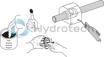
On-shaft relubrication on relubricatable Linear Bushing only until lubricant seeps out.
General mounting instructions
Wiper seals for closed-type Super Linear Bushings and Standard Linear Bushings
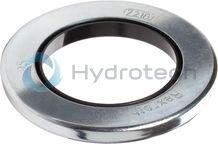
Wiper seals for closed-type Super Linear Bushings and Standard Linear Bushings
Galvanized metal case Elastomer wiper sealCatalog
Instructions
Service
CAD data
Metal cases for Super Linear Bushings and standard Linear Bushings
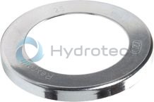
Metal cases for Super Linear Bushings and standard Linear Bushings
Galvanized steelCatalog
Instructions
Service
CAD data
Hydraulic-type lube nipple according to DIN 71412 Form A
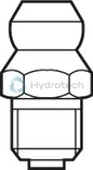
Hydraulic-type lube nipple according to DIN 71412 Form A
Catalog
Instructions
Service
Funnel-type lube nipple according to DIN 3405 Form A
Funnel-type lube nipple according to DIN 3405 Form A
Catalog
Instructions
Service