


BOSCH REXROTH
R103584020
$232.25 USD
- BOSCH REXROTH
- Material:R103584020
- Model:LSA-B-40-DD
Quantity in stock: 0
The Bosch Rexroth LINEAR-SET LSA-B-40-DD (R103584020) is a high-quality linear set designed for precision motion applications. This linear set, crafted from lightweight aluminum, includes a precision housing and a super linear bushing B that lacks a self-alignment feature, ensuring stable and accurate linear motion. The unit comes with two external seals to protect against contaminants and is relubricatable for extended service life. With a standard version shaft diameter of 40mm, the LINEAR-SET LSA-B-40-DD is equipped to handle dynamic load capacities efficiently while maintaining low frictional drags due to its integrated wiper seals on both sides when not under radial load. The frictional forces are contingent upon the speed and lubrication conditions. It boasts an impressive maximum acceleration (amax), breakaway force, and static load rating C, which are indicative of its robustness in various operating conditions. The permissible ambient temperature range for this linear set extends from -20°C to +80°C, which allows it to be used in diverse environments without compromising performance. Additionally, it has been tested for high-speed applications up to a maximum permissible linear speed (vmax), with potential speeds reaching up to 5 m/s. However, at these higher velocities, the service life may be reduced due to increased wear on plastic components. This product has demonstrated durability in testing environments with total travel ranging from 100 km to 1000 km without failure. It's suitable for use where precise guidance is necessary and easy installation is desired. With its fixed working bore diameter and closed format of the linear bushings, the LINEAR-SET LSA-B-40-DD ensures consistent performance in various industrial applications requiring precise linear movement. The weight specification of this model stands at approximately 0.8 kg, offering a balance between structural integrity and ease of handling during installation or maintenance procedures.
Linear set (aluminum), B-40, with two seals
Linear set (aluminum)
Closed
With super LB B
Shaft diameter d = 40
With two seals
Version: Standard
Unpacked Weight: 1.759 kg
For precision guides with easy installation. Fixed working bore diameter.
| Lightweight precision housing (aluminum) |
| super linear bushing B without self-alignment feature |
| External seals |
| Relubricatable |
| Data Sheet | Download Data Sheet |
| 2D CAD | Download 2D CAD |
| 2D CAD | Download 2D CAD |
| 3D CAD | Download 3D CAD |
| 3D CAD | Download 3D CAD |
| Manual | Download Manual |
| Manual | Download Manual |
| Manual | Download Manual |
| Manual | Download Manual |
| Manual | Download Manual |
| Size V | 10 |
| Series | Super B (no self-alignment feature) |
| Footnote friction force FR | Frictional drags generated by linear bushings with integrated wiper seals on two sides when not under radial load. The frictional drags depend on speed and lubrication. |
| Size E1 | 86 |
| Footnote dynamic load capacity C | The load capacities apply for the main direction of loading. If the load direction is not the main direction of loading, the load capacities must be multiplied by the following factors: Ø d 10 to 16: ↩f = 0.82, f0 = 0.86 ↩Ø d 20 to 50: f = 0.82, f0 = 0.78 |
| Size H | 45 |
| Max. acceleration amax | 150 |
| Permissible ambient temperature | -10 °C ... +80 °C |
| Outer diameter D | 62 |
| Size H3 | 14 |
| Breakaway force | 8 |
| Size L3 | 18 |
| Size H4 | 28 |
| Maximum permissible linear speed vmax | 3 |
| Size D | 62 |
| Footnote static load capacity C0 | The load capacities apply for the main direction of loading. If the load direction is not the main direction of loading, the load capacities must be multiplied by the following factors: Ø d 10 to 16: ↩f = 0.82, f0 = 0.86 ↩Ø d 20 to 50: f = 0.82, f0 = 0.78 |
| Size N1 | 44 |
| Static load rating C0 | 5570 |
| Size M | 54 |
| Note: Maximum permissible speed vmax | Speeds of up to 5 m/s possible. Service life is limited by heightened wear to plastic parts. Tests have shown total travel from 50 • 105 m to 100 • 105 m without failure. |
| Friction force | 3 |
| Size A | 108 |
| Productgroup ID | 17 |
| Size N2 | 26 |
| Size E3 | 90 |
| Permissible ambient temperature (max) | |
| Size E2 | 58 |
| Size E4 | 35 |
| Size SW | 6 |
| Permissible ambient temperature (min) | |
| Size S | 10.5 |
| Shaft diameter d | 40 |
| Linear guide type | Linear bushing and shaft |
| Filter for linear bushings and shafts | Linear sets with linear bushings |
| Format of linear bushings | – Closed |
| Dynamic load capacity C | 10070 |
| Size L | 91 |
| Size S2 | 8 |
| Weight | 1.759 |
| Size D1 with tolerance | |
| Size H1 | 90 |
General technical data
|
Ø d |
mm |
10 | 12 | 16 | 20 | 25 | 30 | 40 | 50 |
|
amax |
m/s² |
150 | |||||||
|
vmax 1) |
m/s |
3 | |||||||
|
m |
kg |
0.1 | 0.13 | 0.2 | 0.34 | 0.65 | 0.97 | 1.8 | 3 |
|
FR 2) |
N |
0.5 | 0.8 | 1 | 1.5 | 2 | 2.5 | 3 | 4 |
|
Breakaway force |
N |
1 | 1.5 | 2 | 3 | 4.5 | 6 | 8 | 10 |
|
Shaft radial clearance h6 |
µm |
+ 36 + 9 |
+ 38 + 10 |
+ 43 + 11 |
+ 50 + 12 |
||||
|
Operating conditions |
|||||||||
|
Permissible ambient temperature (min ... max) |
-10 °C ... +80 °C | ||||||||
| 1) | Speeds of up to 5 m/s possible. Service life is limited by heightened wear to plastic parts. Tests have shown total travel from 50 • 105 m to 100 • 105 m without failure. |
| 2) | Frictional drags generated by Linear Bushings with integrated wiper seals on two sides when not under radial load. The frictional drags depend on speed and lubrication. |
Load capacities and load moments
|
Ød |
mm |
10 | 12 | 16 | 20 | 25 | 30 | 40 | 50 |
|
C 1) |
N |
730 | 1020 | 1250 | 2470 | 4820 | 5860 | 10070 | 14730 |
|
C0 1) |
N |
380 | 490 | 620 | 1340 | 2790 | 3570 | 5570 | 8280 |
| 1) | The load ratings apply for the main direction of loading. If the load direction is not the main direction of loading, the load ratings must be multiplied by the following factors: Ø d 10 to 16: f = 0.82, f0 = 0.86 Ø d 20 to 50: f = 0.82, f0 = 0.78 |
| The load ratings are based on a total travel of 100, 00 m. When based on 50 000 m, the values in the table need to be multiplied by 1.26. |
Legend
|
Symbol |
Description |
Unit |
|
Ød |
Shaft diameters |
mm |
|
amax |
Maximum acceleration travel |
m/s2 |
|
C |
Dynamic load capacity |
N |
|
C0 |
Static load capacity |
N |
|
FR |
Friction force |
N |
|
m |
Mass |
kg |
|
vmax |
Maximum permissible speed |
m/s |
Impact of load direction on load rating of closed Linear Bushings
The listed load ratings should be chosen depending on installation in minimum or maximum position and should be based on the calculations. If the load direction is clearly defined and the Linear Bushings can be installed in maximum position, the load ratings Cmax. (dynamic load rating) and C0 max (static load rating) can be used. If aligned installation is not possible or the load direction is not defined, the minimum load ratings must be used.

Reduced load capacity with short stroke
In case of short stroke, the service life of the shaft is less than that of the super Linear Bushing. The load ratings C specified in the tables must therefore be multiplied by the factor f.s .
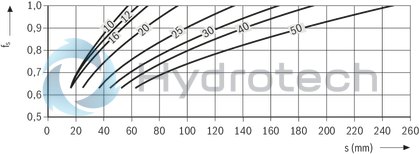
| 1) | fs = factor |
| 2) | s = movement path |
Definition of dynamic load ratings
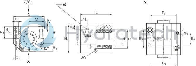
| a) | Lubricating hole sealed with plastic cap |
Dimensions
|
Ød |
mm |
10 | 12 | 16 | 20 | 25 | 30 | 40 | 50 |
|
D |
mm |
19 | 22 | 26 | 32 | 40 | 47 | 62 | 75 |
|
A |
mm |
40 | 43 | 53 | 60 | 78 | 87 | 108 | 132 |
|
E1 |
29 mm ±0.15 | 32 mm ±0.15 | 40 mm ±0.15 | 45 mm ±0.15 | 60 mm ±0.15 | 68 mm ±0.15 | 86 mm ±0.15 | 108 mm ±0.2 | |
|
E2 |
20 mm ±0.15 | 23 mm ±0.15 | 26 mm ±0.15 | 32 mm ±0.15 | 40 mm ±0.15 | 45 mm ±0.15 | 58 mm ±0.15 | 50 mm ±0.2 | |
|
E3 |
mm |
31 | 34 | 42 | 50 | 64 | 72 | 90 | 108 |
|
E4 |
mm |
29 | 32 | 35 | 45 | 20 | 30 | 35 | 42 |
|
H |
mm |
16 | 18 | 22 | 25 | 30 | 35 | 45 | 50 |
|
Tolerance for H 1) |
µm |
+ 8 - 16 |
|||||||
|
H1 |
mm |
31.5 | 35 | 42 | 50 | 60 | 70 | 90 | 105 |
|
H3 |
mm |
10 | 11.5 | 14 | 12.5 | ||||
|
H4 |
mm |
10 | 13 | 16 | 20 | 22 | 28 | 37 | |
|
L |
mm |
36 | 39 | 43 | 54 | 67 | 79 | 91 | 113 |
|
L3 |
mm |
10.5 | 11.5 | 13.5 | 15 | 16 | 18 | 22 | |
|
M 1) |
20 mm ±0.01 | 21.5 mm ±0.01 | 26.5 mm ±0.01 | 30 mm ±0.01 | 39 mm ±0.01 | 43.5 mm ±0.01 | 54 mm ±0.01 | 66 mm ±0.01 | |
|
N1 |
mm |
15 | 16.5 | 21 | 24 | 29 | 34 | 44 | 49 |
|
N2 |
mm |
11 | 13 | 18 | 22 | 26 | 34 | ||
|
S 2) |
mm |
4.3 | 5.3 | 6.6 | 8.4 | 10.5 | 13.5 | ||
|
S1 |
M5 | M6 | M8 | M10 | M12 | M16 | |||
|
S2 3) |
mm |
4 | 5 | 6 | 8 | 10 | |||
|
SW |
mm |
2.5 | 3 | 4 | 5 | 6 | 8 | ||
|
V |
mm |
5 | 6.5 | 8 | 10 | 12 | |||
| 1) | Clamped (fastened) in relation to Ø d. |
| 2) | Fixing screws ISO 4762-8.8 |
| 3) | Pin hole centering. |
Radial clearance
The radial clearance values shown in the table have been determined from statistics and correspond to values expected in practice. The adjustable Linear Sets come clamped to an h5 shaft (lower limit) and set to zero clearance.
Vertical dimension
The tolerance values for the vertical dimension "H" for the Linear Sets shown in the table have been determined from statistics and correspond to values expected in practice.
Bolts
We recommend bolts in accordance with ISO 4762-8.8 for fastening the Linear Sets.
Lubrication
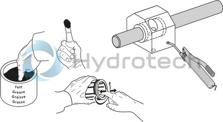
On-shaft relubrication on relubricatable Linear Bushing only until lubricant seeps out.
General mounting instructions
Wiper seals for closed-type Super Linear Bushings and Standard Linear Bushings
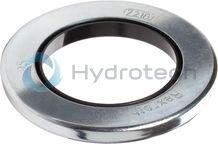
Wiper seals for closed-type Super Linear Bushings and Standard Linear Bushings
Galvanized metal case Elastomer wiper sealCatalog
Instructions
Service
CAD data
Metal cases for Super Linear Bushings and standard Linear Bushings
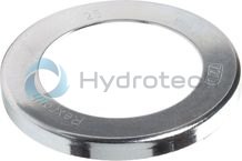
Metal cases for Super Linear Bushings and standard Linear Bushings
Galvanized steelCatalog
Instructions
Service
CAD data
Hydraulic-type lube nipple according to DIN 71412 Form A
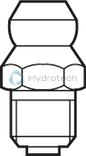
Hydraulic-type lube nipple according to DIN 71412 Form A
Catalog
Instructions
Service
Funnel-type lube nipple according to DIN 3405 Form A
Funnel-type lube nipple according to DIN 3405 Form A
Catalog
Instructions
Service