


BOSCH REXROTH
R102824044
$201.34 USD
- BOSCH REXROTH
- Material:R102824044
- Model:LSACE-40-DD-G
Quantity in stock: 0
The Bosch Rexroth LINEAR-SET LSACE-40-DD-G (R102824044) is a high-quality linear motion set designed for precision applications. This product features a lightweight precision housing made of aluminum and includes a compact linear bushing that is adjustable to ensure optimal performance. The set comes with an integrated wiper seal on both sides, which helps in maintaining cleanliness and protecting against contaminants. With a shaft diameter of 'd', the LSACE-40-DD-G is equipped with two seals and is delivered pre-greased using Dynalub, which provides long-term lubrication and reduces maintenance requirements. This linear set has been engineered to provide smooth motion with minimal friction force (FR), even when not under radial load, thanks to its design that incorporates bushings with integrated wiper seals. It offers a dynamic load capacity (C) that must be adjusted based on the direction of the load for accurate application. The static load capacity also follows similar guidelines for adjustment based on loading directions. The LSACE-40-DD-G can handle a maximum acceleration (amax) and operates efficiently within a specified ambient temperature range. It boasts an impressive breakaway force and can achieve a maximum permissible linear speed (vmax), making it suitable for various dynamic applications where speed and precision are crucial. This Bosch Rexroth linear set comes clamped to the h shaft lower limit and is set to zero clearance, ensuring immediate high precision upon installation. The product belongs to the Compact Series within the Productgroup ID, indicating its space-saving design without compromising on performance. The weight of the unit has been optimized to contribute to overall system efficiency. Overall, the Bosch Rexroth LINEAR-SET LSACE-40-DD-G (R102824044) stands out as an advanced solution for seamless linear motion in various applications where accuracy, speed, and reliability are paramount.
Linear set (aluminum), CE-40, with two seals, greased
Linear set (aluminum)
With compact LB, adjustable
Shaft diameter d = 40
With two seals
Version: Standard
Greased
Unpacked Weight: 0.758 kg
| Lightweight precision housing (aluminum) |
| compact linear bushing |
| Integrated wiper seals |
| Set to zero clearance |
| Initial lubrication with Dynalub 510 |
| Data Sheet | Download Data Sheet |
| 2D CAD | Download 2D CAD |
| 2D CAD | Download 2D CAD |
| 3D CAD | Download 3D CAD |
| 3D CAD | Download 3D CAD |
| Manual | Download Manual |
| Manual | Download Manual |
| Manual | Download Manual |
| Manual | Download Manual |
| Manual | Download Manual |
| Series | Compact |
| Footnote friction force FR | Frictional drags generated by linear bushings with integrated wiper seals on two sides when not under radial load. The frictional drags depend on speed and lubrication. |
| Footnote dynamic load capacity C | The load capacities apply for the main direction of loading. If the load direction is not the main direction of loading, the load capacities must be multiplied by the following factors: ↩Ø d 12 and 16: f = 0.90, f0 = 0.86, ↩Ø d 20 to 50: f = 0.79, f0 = 0.68 |
| Size H | 39 |
| Max. acceleration amax | 150 |
| Permissible ambient temperature | -10 °C ... +80 °C |
| Size E | 69 |
| Outer diameter D | 52 |
| Breakaway force | 8 |
| Size H4 | 24 |
| Maximum permissible linear speed vmax | 5 |
| Size D | 52 |
| Footnote static load capacity C0 | The load capacities apply for the main direction of loading. If the load direction is not the main direction of loading, the load capacities must be multiplied by the following factors: ↩Ø d 12 and 16: f = 0.90, f0 = 0.86, ↩Ø d 20 to 50: f = 0.79, f0 = 0.68 |
| Size N1 | 38 |
| Static load rating C0 | 4650 |
| Friction force | 3 |
| Size A | 87 |
| Radial clearance | Comes clamped to h5 shaft (lower limit) and set to zero-clearance |
| Productgroup ID | 17 |
| Size N2 | 22 |
| Permissible ambient temperature (max) | |
| Size SW | 5 |
| Permissible ambient temperature (min) | |
| Size S | 8.4 |
| Shaft diameter d | 40 |
| Linear guide type | Linear bushing and shaft |
| Format of linear bushings | E – Adjustable |
| Filter for linear bushings and shafts | Linear sets with linear bushings |
| Dynamic load capacity C | 6380 |
| Size L | 60 |
| Weight | 0.758 |
| Size D1 with tolerance | |
| Size H1 | 76 |

General technical data
|
Ø d |
mm |
12 | 16 | 20 | 25 | 30 | 40 | 50 |
|
amax |
m/s² |
150 | ||||||
|
vmax |
m/s |
5 | ||||||
|
m |
kg |
0.08 | 0.11 | 0.15 | 0.27 | 0.4 | 0.75 | 1.2 |
|
FR 1) |
N |
0.8 | 1 | 1.5 | 2 | 2.5 | 3 | 4 |
|
Breakaway force |
N |
1.5 | 2 | 3 | 4.5 | 6 | 8 | 10 |
|
Radial clearance |
Comes clamped to h5 shaft (lower limit) and set to zero clearance | |||||||
|
Operating conditions |
||||||||
|
Permissible ambient temperature (min ... max) |
-10 °C ... +80 °C | |||||||
| 1) | Frictional drags generated by Linear Bushings with integrated wiper seals on two sides when not under radial load. The frictional drags depend on speed and lubrication. |
Load capacities and load moments
|
Ød |
mm |
12 | 16 | 20 | 25 | 30 | 40 | 50 |
|
C 1) |
N |
810 | 1050 | 1410 | 2930 | 3850 | 6380 | 7180 |
|
C0 1) |
N |
490 | 570 | 900 | 1950 | 2790 | 4650 | 5350 |
| 1) | The load ratings apply for the main direction of loading. If the load direction is not the main direction of loading, the load ratings must be multiplied by the following factors: Ø d 12 and 16: f = 0,90, f0 = 0.86, Ø d 20 to 50: f = 0.79, f0 = 0.68 |
| The load ratings are based on a total travel of 100, 00 m. When based on 50 000 m, the values in the table need to be multiplied by 1.26. |
Legend
|
Symbol |
Description |
Unit |
|
Ød |
Shaft diameters |
mm |
|
amax |
Maximum acceleration travel |
m/s2 |
|
C |
Dynamic load capacity |
N |
|
C0 |
Static load capacity |
N |
|
FR |
Friction force |
N |
|
m |
Mass |
kg |
|
vmax |
Maximum permissible speed |
m/s |
Effect of load direction on load rating
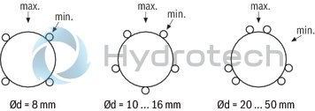
The listed load ratings should be chosen depending on installation in minimum or maximum position and should be based on the calculations. If the load direction is clearly defined and the Linear Bushings can be installed in maximum position, the load ratings Cmax. (dynamic load rating) and C0 max (static load rating) can be used. If aligned installation is not possible or the load direction is not defined, the minimum load ratings must be used.
Reduced load capacity with short stroke
In case of short stroke, the service life of the shafts is less than that of Linear Bushings. The load ratings C specified in the tables must therefore be multiplied by the factor f.s .
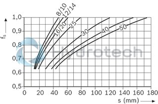
| 1) | fs = factor |
| 2) | s = stroke |
Definition of dynamic load ratings
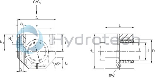
Dimensions
|
Ød |
mm |
12 | 16 | 20 | 25 | 30 | 40 | 50 |
|
D |
mm |
19 | 24 | 28 | 35 | 40 | 52 | 62 |
|
A |
mm |
40 | 45 | 53 | 62 | 67 | 87 | 103 |
|
E |
29 mm ±0.15 | 34 mm ±0.15 | 40 mm ±0.15 | 48 mm ±0.15 | 53 mm ±0.15 | 69 mm ±0.15 | 82 mm ±0.15 | |
|
H |
mm |
17 | 19 | 23 | 27 | 30 | 39 | 47 |
|
Tolerance for H 1) |
µm |
+ 12 - 12 |
+ 13 - 12 |
+ 14 - 12 |
||||
|
H1 |
mm |
33 | 38 | 45 | 54 | 60 | 76 | 92 |
|
H4 |
mm |
11 | 13 | 15 | 17 | 19 | 24 | 30 |
|
L |
mm |
28 | 30 | 40 | 50 | 60 | 70 | |
|
N1 |
mm |
16 | 18 | 22 | 26 | 29 | 38 | 46 |
|
N2 |
mm |
11 | 13 | 18 | 22 | 26 | ||
|
S 2) |
mm |
4.3 | 5.3 | 6.6 | 8.4 | 10.5 | ||
|
S1 |
M5 | M6 | M8 | M10 | M12 | |||
|
SW |
mm |
2.5 | 3 | 4 | 5 | 6 | ||
| 1) | In relation to Ø d. |
| 2) | Fixing screws ISO 4762-8.8 |
Legend
|
Symbol |
Description |
Unit |
|
Ød |
Shaft diameters |
mm |
|
C/C0 |
Main direction of loading |
Initial lubrication
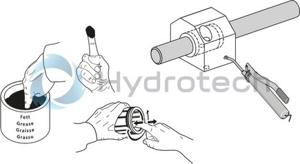
Linear bushings come with initial lubrication. Grease the Linear Bushings before use. Service life data is based on initial lubrication and relubricated Linear Bushings.
Wiper seals for eLINE Linear Bushings and Compact Linear Bushings

Wiper seals for eLINE Linear Bushings and Compact Linear Bushings
Galvanized metal case Elastomer wiper sealCatalog
Instructions
Service
CAD data