BOSCH REXROTH
R072521000
$172.44 USD
- BOSCH REXROTH
- Material:R072521000
- Model:TORQUE RESIST.BUSH KBDR4-F-10DD
Quantity in stock: 0
The Bosch Rexroth TORQUE RESIST.BUSH KBDR4-F-10DD (R072521000) is a high-performance torqueresistant linear bushing designed for self-supporting, torsionally stiff guides with only one shaft. This flanged version comes equipped with two integrated wiper seals to maintain cleanliness within the system and ensure long-lasting operation. The KBDR4-F-10DD features four ball guide grooves which are critical for transferring torque, making it suitable for applications requiring precise motion control and resistance to torsional forces. The bushing's outer sleeve is hardened and ground to provide a durable and robust interface, while the POM ball retainer and balls made of rolling bearing steel ensure smooth, reliable motion. The product is also relubricatable, which contributes to reduced maintenance requirements and extended service life. It has been designed to work with shaft profiles that have machined ball guide grooves, tailored to customer specifications. Moreover, the KBDR4-F-10DD boasts impressive load capacities, both in terms of dynamic load with minimal values as specified by Bosch Rexroth due to variable loading directions, and static torsional moment load capacity. It operates efficiently within a wide range of ambient temperatures from minimum to maximum degrees Celsius as indicated in its specifications. This linear bushing's size V series torque product group ID indicates its place within Bosch Rexroth's lineup of precision components. Its dynamic torsional moment load capacity further exemplifies its capability in demanding applications. With its weight listed at . kg, this component strikes an optimal balance between strength and mass. In summary, the Bosch Rexroth TORQUE RESIST.BUSH KBDR4-F-10DD is an adaptable and robust solution for linear motion systems that require high torque resistance while maintaining precise linear movement.
Torque-resistant LB, 4-F-10, with two seals
Torque-resistant linear bushing (flanged version)
Ball guide grooves = 4
Shaft diameter d = 10
With two seals
Without shaft
Unpacked Weight: 0.103 kg
| For self-supporting, torsionally stiff guides with only one shaft |
| With four ball guide grooves for transferring torque |
| Matching shaft profiles with machined ball guide grooves |
| Shafts machined to customer specification |
| Integrated wiper seals |
| Hardened and ground outer sleeve |
| POM ball retainer |
| Balls made of rolling bearing steel |
| Relubricatable |
| Data Sheet | Download Data Sheet |
| 2D CAD | Download 2D CAD |
| 2D CAD | Download 2D CAD |
| Manual | Download Manual |
| Manual | Download Manual |
| Manual | Download Manual |
| Manual | Download Manual |
| Manual | Download Manual |
| Size V | 4.4 |
| Size L with tolerance | 33 mm -0,2 |
| Series | Torque |
| Productgroup ID | 17 |
| Size D h6 | 21 |
| Footnote dynamic load capacity C | The load capacities indicated are minimal values as the direction of loading cannot always be clearly defined. |
| Shaft diameter, detailed | 10 |
| Permissible ambient temperature (max) | |
| Max. acceleration amax | 150 |
| Permissible ambient temperature | -10 °C ... +80 °C |
| Permissible ambient temperature (min) | |
| Maximum permissible linear speed vmax | 3 |
| Static torsional moment load capacity Mt0 | 8.2 |
| Size S | 4.5 |
| Size D1 | 42 |
| Footnote static load capacity C0 | The load capacities indicated are minimal values as the direction of loading cannot always be clearly defined. |
| Size L1 | 6 |
| Static load rating C0 | 5070 |
| Shaft diameter d | 10 |
| Dynamic torsional moment load capacity Mt | 3.5 |
| Linear guide type | Linear bushing and shaft |
| Filter for linear bushings and shafts | Linear bushings |
| Format of linear bushings | F – Flange |
| Dynamic load capacity C | 2170 |
| Size L | 33 |
| Footnote diameter d | Actual shaft diameter varies |
| Size D2 | 32 |
| Size L2 | 10.5 |
| Weight | 0.103 |
| Size D1 with tolerance | 42 mm |
General technical data
|
Ø d 1) |
mm |
6 | 8 | 10 | 13 | 16 | 20 | 25 | 30 | 40 | 50 |
|
amax |
m/s² |
150 | |||||||||
|
vmax |
m/s |
3 | |||||||||
|
m |
kg |
0.037 | 0.042 | 0.094 | 0.1 | 0.2 | 0.22 | 0.32 | 0.51 | 1.15 | 2.1 |
|
Operating conditions |
|||||||||||
|
Permissible ambient temperature (min ... max) |
-10 °C ... +80 °C | ||||||||||
| 1) | Actual shaft diameter varies |
Load capacities and load moments
|
Ød 1) |
mm |
6 | 8 | 10 | 13 | 16 | 20 | 25 | 30 | 40 | 50 |
|
C 2) |
N |
970 | 1150 | 2170 | 2120 | 4860 | 6200 | 9800 | 14800 | 24400 | 36600 |
|
C0 2) |
N |
2280 | 2870 | 5070 | 4890 | 11200 | 11300 | 16100 | 23200 | 37500 | 74200 |
|
Mt |
Nm |
1.2 | 1.7 | 3.5 | 16.7 | 48 | 66 | 129 | 229 | 500 | 1100 |
|
Mt0 |
Nm |
2.4 | 3.7 | 8.2 | 39.2 | 110 | 133 | 239 | 412 | 882 | 3180 |
| 1) | Actual shaft diameter varies |
| 2) | The load ratings indicated are minimal values as the load direction cannot always be clearly defined. |
| The load ratings are based on a total travel of 100, 00 m. When based on 50 000 m, the values in the table need to be multiplied by 1.26. |
Legend
|
Symbol |
Description |
Unit |
|
Ød |
Shaft diameters |
mm |
|
amax |
Maximum acceleration travel |
m/s2 |
|
C |
Dynamic load capacity |
N |
|
C0 |
Static load capacity |
N |
|
m |
Mass |
kg |
|
Mt |
Dynamic torsional moment load capacity |
Nm |
|
Mt0 |
Static torsional moment laod capacity |
Nm |
|
vmax |
Maximum permissible speed |
m/s |
Reduced load capacity with short stroke
In case of short stroke, the service life of the shaft is less than that of the torque-resistant Linear Bushing. The dynamic load ratings C in the tables must therefore be multiplied by the factor fs .
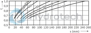
| 1) | fs = factor |
| 2) | s = movement path |
Service life, shaft straightness, stabilized installation
Definition of dynamic load ratings
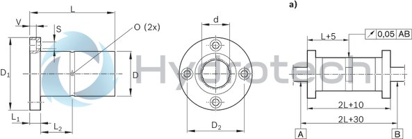
| a) | Concentricity tolerance |
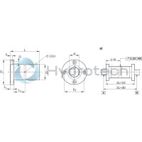
Dimensions
|
Ød 1) |
mm |
6 | 8 | 10 | 13 | 16 | 20 | 25 | 30 | 40 | 50 | |
|
Ød ‒ actual 2) |
mm |
6 | 8 | 10 | 13 | 16 | 18.2 | 23 | 28 | 37.4 | 47 | |
|
D |
h6 |
mm |
14 | 16 | 21 | 24 | 31 | 32 | 37 | 45 | 60 | 75 |
|
D1 |
mm |
30 | 32 | 42 | 43 | 50 | 51 | 60 | 70 | 90 | 113 | |
|
D2 |
mm |
22 | 24 | 32 | 33 | 40 | 47 | 54 | 72 | 91 | ||
|
L |
25 mm -0.2 | 33 mm -0.2 | 36 mm -0.2 | 50 mm -0.2 | 60 mm -0.2 | 70 mm -0.3 | 80 mm -0.3 | 100 mm -0.3 | 112 mm -0.3 | |||
|
L1 |
mm |
5 | 6 | 7 | 9 | 10 | 14 | 16 | ||||
|
L1 |
5 mm | 6 mm | 7 mm | 9 mm | 10 mm | 14 mm | 16 mm | |||||
|
L2 |
mm |
7.5 | 10.5 | 11 | 18 | 23 | 26 | 30 | 36 | 40 | ||
|
O |
mm |
1 | 1.5 | 2 | 3 | 4 | ||||||
|
S 3) |
mm |
3.4 | 4.5 | 5.5 | 6.6 | 9 | 11 | |||||
|
V |
mm |
3.3 | 4.4 | 5.4 | 6.5 | 8.6 | 11 | |||||
| 1) | Actual shaft diameter varies |
| 2) | h7 tolerance |
| 3) | Fixing screws ISO 4762-8.8 |
Recommended housing tolerance: H6 or H7
Installation
Radial clearance: approx. ± 5 μm
Linear bushing and shaft for torque-resistant Linear Bushings with four ball guide grooves come separately. Align the tracks and wiper seals when inserting the shaft and make sure they are not skewed!
General mounting instructions
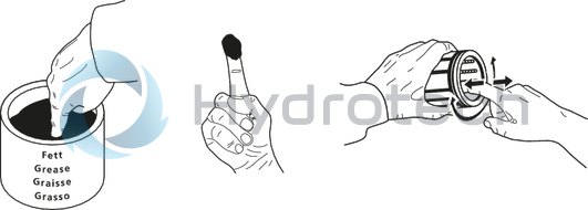
Initial lubrication
Linear bushings do not come with initial lubrication. Grease the Linear Bushings before use. Service life data is based on initial lubrication and relubricated Linear Bushings.