

BOSCH REXROTH
R911381173
$1,995.75 USD
- BOSCH REXROTH
- Material:R911381173
- Model:CSB02.1A-ET-EC-NN-L3-NN-NN-AW
Quantity in stock: 0
The Bosch Rexroth CSB02.1A-ET-EC-NN-L3-NN-NN-AW (R911381173) is a sophisticated single-axis control unit designed to cater to a diverse array of applications. This unit stands out for its versatility, supporting an extensive range of control communication protocols and encoder interfaces, which makes it highly adaptable to various operational requirements. The control unit is engineered to seamlessly integrate with systems that require precise motion control, ensuring optimal performance and reliability. Its capability to work with multiple encoder types allows for flexibility in system design and retrofitting into existing setups without the need for extensive modifications. The Bosch Rexroth CSB02.1A model is particularly suitable for applications that demand high levels of accuracy and efficiency, such as automated manufacturing processes, robotics, and CNC machinery. The user-friendly interface of this control unit ensures ease of setup and maintenance, reducing downtime and enhancing productivity. Its robust construction adheres to the high-quality standards set by Bosch Rexroth, ensuring long-term durability even in demanding industrial environments. The CSB02.1A-ET-EC-NN-L3-NN-NN-AW model embodies a commitment to advanced technology and precision engineering, providing users with a reliable solution for their single-axis control needs.
Unpacked Weight: 0.480 kg
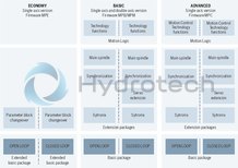
The BASIC single axis control units are suitable for a variety of applications. They support a wide range of control communication and encoder interfaces.
| Operating panel | with advanced control panel, firmware must be ordered separately |
| Interface 4 | not fitted |
| Interface 1 | Multi-encoder interface |
| Productgroup ID | 4,6 |
| Interface 2 | not fitted |
| Interface 3 (safety technology) | STO (Safe Torque Off) |
| Communication | MultiEthernet |
| Weight | 0.480 |
|
01 |
02 |
03 |
04 |
05 |
06 |
07 |
08 |
09 |
10 |
11 |
||||||||
|
CSB |
02 |
. |
- |
- |
- |
- |
- |
- |
- |
|
01 |
IndraDrive - CSB02 |
CSB |
|
02 |
Line |
02 |
|
Variant |
||
|
03 |
1 |
1 |
|
Interface equipment |
||
|
04 |
Basic functionality |
A |
|
Extended functionality |
B |
|
|
Communication |
||
|
05 |
Multi-Ethernet |
ET |
|
Interface 1 |
||
|
06 |
Multi-encoder interface |
EC |
|
Interface 2 |
||
|
07 |
Not equipped |
NN |
|
PROFIBUS |
PB |
|
|
CANopen |
CN |
|
|
Multi-encoder interface |
EC |
|
|
Encoder emulation |
EM |
|
|
Engineering port |
EP |
|
|
Interface 3 (safety technology)1) |
||
|
08 |
Not equipped |
NN |
|
STO (Safe Torque Off) |
L3 |
|
|
Safe Motion2) |
S4 |
|
|
Safe Motion2) |
S5 |
|
|
Safe Motion Bus2) |
SB |
|
|
Interface 4 |
||
|
09 |
Not equipped |
NN |
|
Multi-encoder interface3) |
EC |
|
|
Encoder emulation4) |
EM |
|
|
Digital/analog I/O extension2) |
DA |
|
|
Other version |
||
|
10 |
None |
NN |
|
Firmware |
||
|
11 |
With ADVANCED operating panel, firmware must be ordered separately |
AW |
|
With STANDARD operating panel, firmware must be ordered separately |
FW |
|
|
Without operating panel and firmware |
NW |
|
| 1) | The L3, S4, S5 and SB interfaces ensure both the function and its certification. |
| 2) | Only if interface equipment = B |
| 3) | Only if interface equipment = B and interface 2 = PB, CN or EP |
| 4) | Only if interface equipment = B and interface 2 = PB, CN, EP or EC |
IndraDrive control units
|
Type |
CSB02.1A-ET | CSB02.xB-ET | ||
|
Communication |
||||
|
Multi-Ethernet |
Sercos III, EtherCAT®, PROFINET IO, EtherNet/IP, Powerlink |
● | ● | |
|
Analog interface 1) |
○ | ○ | ||
|
PROFIBUS |
○ | ○ | ||
|
CANopen |
○ | ○ | ||
|
Extensions |
||||
|
Encoder emulation |
○ | ● | ||
|
MultiEncoder interface |
○ | ○ | ||
|
Encoder emulation with level converter function |
○ | ○ | ||
|
Digital/analog I/O extension |
- | ○ | ||
|
Extra engineering port |
○ | - | ||
|
Operating panel |
||||
|
Standard operating panel |
● | ● | ||
|
ADVANCED operating panel with memory card slot |
○ | ○ | ||
|
Cycle times (performance ECONOMY or BASIC/ADVANCED) |
||||
|
Current control 2) |
125/62,5 µs | |||
|
Speed control 2) |
250/125 µs | |||
|
Position control 2) |
500/250 µs | |||
|
PWM frequency |
||||
|
2 kHz 3) |
● | ● | ||
|
4 kHz |
● | ● | ||
|
8 kHz |
● | ● | ||
|
12 kHz 3) |
● | ● | ||
|
16 kHz |
● | ● | ||
|
Inputs/outputs |
||||
|
Digital inputs/of which utilizable as touch probes |
7/2 | 11/2 | ||
|
Digital inputs/outputs (any configurable) |
1 | 5 | ||
|
Analog inputs |
±10 V |
1 | 1 | |
|
±10 V or 0 ... 20 mA |
- | 2 | ||
|
Analog outputs |
±10 V |
- | 2 | |
|
Relay outputs |
1 | 1 | ||
| 1) | Via onboard analog input and optional encoder emulation |
| 2) | ADVANCED performance on BASIC control units can only be used with limitations |
| 3) | Not with ADVANCED performance |
Onboard encoder interface
|
MultiEncoder interface |
Motors (MAD, MAF, MCL, MKE, MS2N, MSK, MSM), Hiperface®, EnDat 2.1, EnDat 2.2, 1 Vss, 5 V TTL, SSI, Resolver |
● | ● |
Safety options according to EN 13849-1 and EN 62061
|
Safe Torque Off |
Category 4 PL e/SIL 3 |
○ | ○ | |
|
Safe Motion |
Category 3 PL d/SIL 2 or category 4 PL e/SIL 3 |
- | ○ | |
|
Safe Motion Bus |
Category 3 PL d/SIL 2 or category 4 PL e/SIL 3 |
- | ○ |
|
Legend |
|
|
● |
Standard |
|
○ |
Option |
|
▼ |
In preparation |
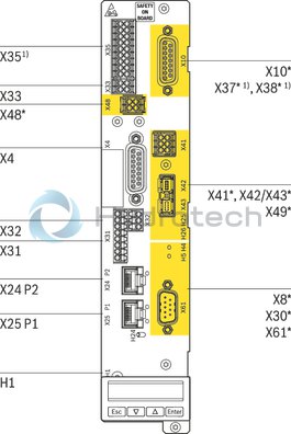
CSB02
|
Front view |
Connection point |
Description |
|
X4 |
Encoder evaluation EC |
|
X8* |
Encoder evaluation EC Encoder emulation EM |
|
|
X10* |
Encoder evaluation EC Encoder emulation EM |
|
|
X24 P2, X25 P1 |
Multi-Ethernet communication ET |
|
|
X30* |
PROFIBUS communication PB |
|
|
X31 |
Digital inputs/outputs Probe input |
|
|
X32 |
Analog inputs |
|
|
X33 |
Voltage input (24 V, 0 V) Standby relay |
|
|
X351) |
Digital inputs/outputs; Analog inputs (current/voltage) Analog outputs (voltage) |
|
|
X37* 1) |
Digital inputs/outputs |
|
|
X38* 1) |
Analog inputs/outputs |
|
|
X41* |
S4, S5, SB safety technology (Not required for SB: X41, X42 and X43; LEDs included) |
|
|
X42/X43* |
||
|
X48* |
Safety Technology (Only available with S4, S5 and SB safety technology) |
|
|
X49* |
L3 safety technology |
|
|
X61* |
Communication CANopen CN |
|
|
H1 |
Operating panel interface |
|
1) CSB02.xB only |
|
* Optional connection points; optional connection points are highlighted in yellow in the figure. |
Motion Control system, based on drive system IndraDrive
MLD
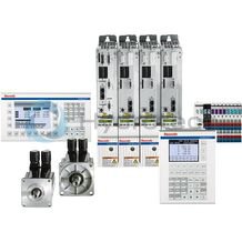
Motion Control system, based on drive system IndraDrive
MLD
Certified safety technology Drive-integrated Motion Control acc. to IEC 61131-3 Electronic synchronization of up to 10 servo-axes Intuitive engineering thanks to the IndraWorks software framework Optional technology and communication interfacesApplication description
Documentation MLD, 13VRS
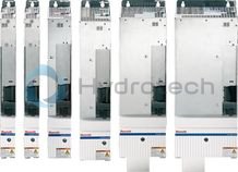
IndraDrive C
HCS02
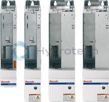
IndraDrive C
HCS02
1.5 kW ... 11 kW power range 12 A ... 70 A maximum current 200 V ... 500 V direct power supply 2.5x overload capacity Compact design for single-axis applicationsOperating instructions
Project planning guide
Project planning guide
Spare parts & repair
CAD Download
IndraDrive C
HCS03
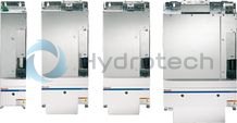
IndraDrive C
HCS03
22 kW ... 110 kW power range 70 A ... 350 A maximum current 400 V ... 500 V direct power supply 1.5x overload capacity Compact design for single-axis applicationsOperating instructions
Project planning guide
System documentation
Project planning guide
Spare parts & repair
CAD Download
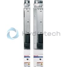
IndraDrive M
HMS01 single-axis inverter
IndraDrive M
HMS01 single-axis inverter
5.5 kW ... 132 kW power range 12.1 A ... 250 A continuous current 12 A ... 350 A maximum current 540 V ... 750 V DC line voltage Protection type IP20Operating instructions
Project planning guide
Project planning guide
Spare parts & repair
CAD Download
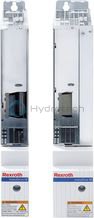
IndraDrive M
HMD01 double-axis inverter
IndraDrive M
HMD01 double-axis inverter
3 kW ... 7.5 kW power range 7 A ... 20 A continuous current 12 A ... 36 A maximum current 540 V ... 750 V DC line voltage Protection type IP20Operating instructions
Project planning guide
Project planning guide
Spare parts & repair
CAD Download
IndraDrive M
HMS02 - single-axis inverter
IndraDrive M
HMS02 - single-axis inverter
5.5 kW ... 11 kW power range 13.8 A ... 25 A continuous current 28 A ... 54 A maximum current 540 V ... 750 V DC line voltage Protection type IP20Operating instructions
Instruction manual
Project planning guide
Spare parts & repair
CAD Download
IndraDrive ML
HMU05 - supply device/inverter
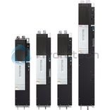
IndraDrive ML
HMU05 - supply device/inverter
Universally usable as supply device or as single-axis inverter 110 kW ... 4 MW power range 380 V ... 690 V mains connection voltage 540 V ... 1100 V DC line voltage Rectifier and regeneration function (when used as supply unit)Project planning guide
Instruction manual
Spare parts & repair
CAD Download
IndraDrive
FWA firmware
IndraDrive
FWA firmware
Comprehensive basic package for implementing most drive tasks Min. 250 µs position controller and bus cycle performance Anti-vibration filter for avoiding vibrations Integrated IEC-compliant Motion Logic Manufacturer-independent Sercos and CANopen CiA 402 device profileApplication description
Application description
Release Notes
Spare parts & repair
CAD Download