

BOSCH REXROTH
R911170786
$723.90 USD
- BOSCH REXROTH
- Material:R911170786
- Model:R-IB IL AO 2/U/BP-PAC
Quantity in stock: 0
The Bosch Rexroth R-IB IL AO 2/U/BP-PAC (R911170786) is an advanced inline analog output module designed to integrate seamlessly into an Inline station, providing precise control for outputting analog voltage signals. This particular module is capable of delivering outputs with a V wire connection technique, ensuring reliable and accurate signal transmission for various automation tasks. It comes complete with essential accessories, including a connection plug and a labeling field, which facilitate easy installation and maintenance. The R-IB IL AO 2/U/BP-PAC module is engineered to meet the stringent requirements of complex industrial applications where high precision in signal processing is paramount. Its robust design and compatibility with the Inline station make it a versatile component for any system that requires exact analog output capabilities.
Inline connector
The modular, compact equipment configuration of the I/O systems from Rexroth offers you maximum flexibility for the cost-effective implementation of your individual machine concepts. The I/O modules have robust design and mechanics, are easy to use, have a quick reaction time and are quick to install – both in the control cabinet and in the field. Open communication standards allow you perfect integration of the I/O modules with maximum availability.
Unpacked Weight: 0.098 kg
This module is designed for use within an Inline station. It is used to output analog voltage signals.
| Data Sheet | Download Data Sheet |
| 3D CAD | Download 3D CAD |
| Manual | Download Manual |
| Air pressure (operation) | 70-106 kPa (up to 3,000 m above sea level) |
| Width | 12.2 |
| Productgroup ID | 4,6 |
| Height | 136.8 |
| International protection code | IP20 |
| Permissible air humidity (storage) | 10-95 |
| Voltage output signal | 0-10 V; -10-10 V |
| Permissible air humidity (transport) | 10-95 |
| Number of channels | 2 |
| Connection type | Zugfederanschluss |
| Connection techniques | 2-Leitertechnik |
| Depth | 71.5 |
| Weight | 0.098 |
| Ambient temperature (during operation) | -25-55 |
| Ambient temperature (storage and transport) | -25-85 |
| Conductor cross-section | Rigid: 0.08-0.5 mm²,Flexible: 0.08-0.5 mm²,AWG: 28 ... 16 |
General data
|
Type |
R-IB IL AO 2/U/BP-PAC | |
|
Weight 1) |
g |
96.8 |
|
Operating mode |
Process data mode with 2 words | |
|
Actuator connection type |
2-wire technology | |
|
Ambient temperature (operation) |
-25 °C ... +55 °C | |
|
Ambient temperature (storage/transport) |
-25 °C ... +85 °C | |
|
Permissible relative humidity (operation) |
10 % ... 95 % acc. to DIN EN 61131-2 | |
|
Permissible relative humidity (storage/transport) |
10 % ... 95 % acc. to DIN EN 61131-2 | |
|
Air pressure (operation) |
70 kPa ... 106 kPa (up to 3000 m above sea level) | |
|
Air pressure (storage/transport) |
70 kPa ... 106 kPa (up to 3000 m above sea level) | |
|
Protection type |
IP20, IEC 60529 | |
|
Protection class |
III, EN 61113-2, IEC 61113-2 | |
| 1) | Including plug |
Connection data
|
Type |
R-IB IL AO 2/U/BP-PAC | |
|
Designation |
Inline connection plug | |
|
Connection type |
Tension spring modules | |
|
Conductor cross-section solid/flexible/AWG |
0.08 mm² ... 1.5 mm² 0.08 mm² ... 1.5 mm² 28 ... 16 |
|
Interface local bus
|
Type |
R-IB IL AO 2/U/BP-PAC | |
|
Connection type |
Inline data jumper | |
|
Transmission speed |
kBit/s |
500 |
Inline potentials/performance balance
|
Type |
R-IB IL AO 2/U/BP-PAC | ||
|
Logic voltage UL |
V |
7.5 | |
|
Typical current consumption from UL |
mA |
≈ 33 | |
|
Maximum current consumption from UL |
mA |
≤ 40 | |
|
Peripheral supply voltage UANA |
V DC |
24 | |
|
Typical current consumption from UANA |
No load (RL > 10 MΩ) |
mA |
18 |
|
Full load (RL = 2 kΩ) |
mA |
25 | |
|
Maximum current consumption from UANA |
No load (RL > 10 MΩ) |
mA |
28 |
|
Full load (RL = 2 kΩ) |
mA |
35 | |
|
Typical power consumption total |
No load (RL > 10 MΩ) |
W |
0.68 |
|
Full load (RL = 2 kΩ) |
W |
0.85 | |
Supply of module electronics and peripherals via bus coupler/power feed module
|
Type |
R-IB IL AO 2/U/BP-PAC | |
|
Connectivity technology |
Potential jumpers | |
Analog outputs
|
Type |
R-IB IL AO 2/U/BP-PAC | ||
|
Number of analog outputs |
2 | ||
|
Signal connection type |
2-wire technology, single ended | ||
|
Signals/resolution in the process data word (quantization) ‒ voltage |
-10 V ... +10 V |
333.33 μV/LSB | |
|
0 V ... +10 V |
333.33 μV/LSB | ||
|
Output value representation |
-10 V ... +10 V |
16 bits two complement | |
|
0 V ... +10 V |
16 bits two complement | ||
|
Smallest DAC quantization step |
-10 V ... +10 V |
2.667 mV (13 bits) | |
|
0 V ... +10 V |
2.667 mV (12 bits) | ||
|
Basic error limit 1) |
% |
± 0.02 | |
|
Output load |
kΩ |
≥ 2 | |
|
Process data update time including conversion time of the digital analog converter |
1 INTERBUS cycle (depending on the bus configuration); < 1 ms | ||
|
Typical signal rise time (slew rate) |
10 % ... 90 % of the final value |
µs |
15 |
|
0 % ... > 99 % of the final value |
µs |
31 | |
|
Typical signal rise time (slew rate) (-9 V ... +9 V) |
At no load |
V/μs |
0.35 |
|
Ohmic load RL = 2 kΩ |
V/μs |
0.24 | |
|
Ohmic/capacitive load RL = 2 kΩ/CL = 10 nF |
V/μs |
0.24 | |
|
Ohmic/capacitive load RL = 2 kΩ/CL = 220 nF |
V/μs |
0.09 | |
|
Line type LiYCY (TP) (shielded twisted power plant line) |
Permissible cable length |
m |
≥ 500 |
|
Electrical properties 2) |
N x 2 x 0.5 | ||
|
Inductance |
mH/km |
0.67 | |
|
Operating capacity |
nF/km |
120 | |
| 1) | Typically from output range end value |
| 2) | N = Number of wire pairs, wire cross-section ≥ 0.5 mm2 |
Tolerance and temperature behavior (absolute tolerance data)
| Typical | Maximum | ||
|
The tolerance specifications refer to the output range end value of 10 V |
|||
|
Tolerance at 23 °C |
|||
|
Total offset voltage |
mV |
± 0.5 | ± 4 |
|
Gain tolerance |
mV |
± 2.5 | ± 6 |
|
Differential non-linearity |
mV |
± 1.3 | ± 3.9 |
|
Total tolerance at 23 °C |
mV |
± 4.3 | ± 13.9 |
|
Temperature behavior from -25 °C to +55 °C |
|||
|
Offset voltage drift TKVO |
± 2.1 mV | ± 5 mV | |
|
Gain drift TKG |
± 9.2 mV | ± 20 mV | |
|
Total voltage drift TKges = TKVO + TKG |
± 11.3 mV | ± 25 mV | |
|
Total tolerance of voltage output for -25 °C to 55 °C Offset, gain, linearity and drift tolerance |
± 15.6 mV | ± 38.9 mV | |
Tolerance and temperature behavior (relative tolerance data)
| Typical | Maximum | ||
|
The tolerance specifications refer to the output range end value of 10 V |
|||
|
Tolerance at 23 °C |
|||
|
Total offset voltage |
% |
± 0.005 | ± 0.027 |
|
Gain tolerance |
% |
± 0.025 | ± 0.06 |
|
Differential non-linearity |
% |
± 0.013 | ± 0.027 |
|
Total tolerance at 23 °C |
% |
± 0.09 | ± 0.14 |
|
Temperature behavior from -25 °C to +55 °C |
|||
|
Offset voltage drift TKVO |
4 ppm/K | 10 ppm/K | |
|
Gain drift TKG |
18 ppm/K | 40 ppm/K | |
|
Total voltage drift TKges = TKVO + TKG |
23 ppm/K | 50 ppm/K | |
|
Total tolerance of voltage output for -25 °C to 55 °C Offset, gain, linearity and drift tolerance |
± 0.16 % | ± 0.39 % | |
Additional tolerances under the influence of electromagnetic fields
|
Type |
R-IB IL AO 2/U/BP-PAC | ||
|
Type of electromagnetic interference |
Typical deviation from the measurement range end value ‒ relative |
||
|
Electro-magnetic fields Field strength 10 V/macc. to EN 61000-4-3/IEC 61000-4-3 |
Relative |
% |
< ± 0.2 |
|
Absolute |
mV |
< ± 20 | |
|
Line-fed disturbances III (test voltage 10 V)acc. to EN 61000-4-6/IEC 61000-4-6 |
Relative |
% |
< ± 2.8 |
|
Absolute |
mV |
< ± 280 | |
Protective devices
|
Type |
R-IB IL AO 2/U/BP-PAC | |
|
Transient protection of the analog outputs |
Yes | |
Electrical isolation/insulation of the voltage ranges
|
Type |
R-IB IL AO 2/U/BP-PAC | |
|
Common potentials |
||
|
24 V peripheral voltage, 24 V segment voltage and GND are on the same potential. FE represents a separate potential area. |
||
|
Separate potentials in the system of bus coupler/feed module and I/O module |
||
|
Test distance |
Test voltage | |
|
7.5 V supply (bus logic), 24 V supply UANA/peripherals |
500 V AC, 50 Hz, 1 min. | |
|
7.5 V supply (bus logic), 24 V supply UANA/function earth |
500 V AC, 50 Hz, 1 min. | |
|
24 V supply (peripherals)/function earth |
500 V AC, 50 Hz, 1 min. | |
Error messages to the higher-level control or computer system
|
Type |
R-IB IL AO 2/U/BP-PAC | |
|
Error message |
Upon failure or undershooting of the logic voltage UL: Peripheral error message to the bus coupler | |
|
Approvals |
|
The current approvals can be found at www.boschrexroth.com. |
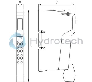
Dimensions
|
Type |
R-IB IL AO 2/U/BP-PAC | |
|
A |
mm |
12.2 |
|
B |
mm |
136.8 |
|
C |
mm |
71.5 |
|
Note on dimensions |
The depth applies when using a support rail TH 35-7.5 (acc. to EN 60715). | |