

BOSCH REXROTH
R911170768
$801.35 USD
- BOSCH REXROTH
- Material:R911170768
- Model:R-IB IL 24 DO 32/HD-PAC
Quantity in stock: 0
The Bosch Rexroth R-IB IL 24 DO 32/HD-PAC (R911170768) is a robust digital output module designed for seamless integration into an Inline station, providing efficient and reliable output of digital signals. This particular module is capable of handling outputs in VDC and mA, making it versatile for a wide range of applications. It employs a wire connection technique that ensures secure and stable connections for consistent performance. The module comes complete with necessary accessories, including a connection plug and a labeling field, which simplifies installation and maintenance while promoting organization within the system. The R-IB IL 24 DO 32/HD-PAC is engineered to meet the demanding needs of complex automation systems where precision and durability are paramount. With its capability to output multiple digital signals, this module is well-suited for tasks that require high-density output in a compact form factor. Its design reflects Bosch Rexroth's commitment to producing high-quality components that enhance the functionality and reliability of industrial automation systems. The R-IB IL 24 DO 32/HD-PAC stands as an essential component for professionals looking to optimize their control systems with state-of-the-art technology.
Inline connector
The modular, compact equipment configuration of the I/O systems from Rexroth offers you maximum flexibility for the cost-effective implementation of your individual machine concepts. The I/O modules have robust design and mechanics, are easy to use, have a quick reaction time and are quick to install – both in the control cabinet and in the field. Open communication standards allow you perfect integration of the I/O modules with maximum availability.
Unpacked Weight: 0.225 kg
This module is designed for use within an Inline station. It is used to output digital signals.
| Data Sheet | Download Data Sheet |
| 3D CAD | Download 3D CAD |
| Manual | Download Manual |
| Air pressure (operation) | 70-106 kPa (up to 3,000 m above sea level) |
| Total current | 8 |
| Air pressure (storage / transport) | 70-106 kPa (up to 3,000 m above sea level) |
| Width | 48.8 |
| Productgroup ID | 4,6 |
| Overload-/ short circuit protection in the segment circuit | Electronic; by eight 4-channel drivers |
| Height | 120 |
| International protection code | IP20 |
| Permissible air humidity (storage) | 10-95 |
| Permissible air humidity (transport) | 10-95 |
| Number of channels | 32 |
| Connection type | Zugfederanschluss |
| Connection techniques | 1-Leitertechnik |
| Depth | 71.5 |
| Weight | 0.225 |
| Ambient temperature (during operation) | -25-55 |
| Ambient temperature (storage and transport) | -25-85 |
| Conductor cross-section | Rigid: 0.2-1.5 mm²,Flexible: 0.2-1.5 mm²,AWG: 24 ... 16 |
General data
|
Type |
R-IB IL 24 DO 32/HD-PAC | |
|
Weight 1) |
g |
195 |
|
Operating mode |
Process data operation with 4 bytes | |
|
Actuator connection type |
1-wire technology | |
|
Ambient temperature (operation) |
-25 °C ... +55 °C | |
|
Ambient temperature (storage/transport) |
-25 °C ... +85 °C | |
|
Permissible relative humidity (operation) |
10 % ... 95 % acc. to DIN EN 61131-2 | |
|
Permissible relative humidity (storage/transport) |
10 % ... 95 % acc. to DIN EN 61131-2 | |
|
Air pressure (operation) |
70 kPa ... 106 kPa (up to 3000 m above sea level) | |
|
Air pressure (storage/transport) |
70 kPa ... 106 kPa (up to 3000 m above sea level) | |
|
Protection type |
IP20, IEC 60529 | |
|
Protection class |
III, VDE 0106, IEC 60536 | |
| 1) | Including plug |
Connection data
|
Type |
R-IB IL 24 DO 32/HD-PAC | |
|
Designation |
Inline connection plug | |
|
Connection type |
Tension spring modules | |
|
Conductor cross-section solid/flexible/AWG |
0.2 mm² ... 1.5 mm² 0.2 mm² ... 1.5 mm² 24 ... 16 |
|
Interface local bus
|
Type |
R-IB IL 24 DO 32/HD-PAC | |
|
Connection type |
Data ranking | |
|
Transmission speed |
kBit/s |
500 |
Supply of module electronics and peripherals via bus coupler/power feed module
|
Type |
R-IB IL 24 DO 32/HD-PAC | |
|
Connectivity technology |
Potential jumpers | |
Inline potentials/performance balance
|
Type |
R-IB IL 24 DO 32/HD-PAC | |
|
Logic voltage |
V DC |
7.5 |
|
Maximum current consumption from UL |
mA |
140 |
|
Maximum power consumption from UL |
W |
1.05 |
|
Segment supply voltage US |
V DC |
24 |
|
Nominal current consumption from US |
≤8 A (16 x 0.5 A/32 x 0.25 A) | |
Digital outputs
|
Type |
R-IB IL 24 DO 32/HD-PAC | |||
|
Number of digital outputs |
32 | |||
|
Nominal output voltage UOut |
V DC |
24 | ||
|
Differential voltage at INenn |
V |
≤ 1 | ||
|
Nominal current INenn each channel |
A |
0.5 | ||
|
Nominal current tolerance |
% |
+ 10 | ||
|
Total current |
A |
8 | ||
|
Nominal load |
Ohmic |
48 Ω |
W |
12 |
|
Lamps |
W |
12 | ||
|
Inductance |
1.2 H; 50 Ω |
VA |
12 | |
|
Signal delay upon turning on of a |
Ohmic nominal load |
µs |
500 | |
|
Lamp nominal load 1) |
ms |
100 | ||
|
Inductive nominal load |
1.2 H; 50 Ω |
ms |
100 | |
|
Signal delay upon deactivating a |
Ohmic nominal load |
ms |
1 | |
|
Lamp nominal load |
ms |
1 | ||
|
Inductive nominal load |
1.2 H; 50 Ω |
ms |
50 | |
|
Maximum switching frequency for a |
Ohmic nominal load |
Hz |
300 | |
|
Lamp nominal load |
Hz |
8 | ||
|
Inductive nominal load |
1.2 H; 50 Ω |
Hz |
0.5 | |
|
Behavior for overload |
Automatic restart | |||
|
Response time for ohmic overload (12 Ω) |
s |
≈ 3 | ||
|
Restart frequency for ohmic overload |
Hz |
≈ 400 | ||
|
Restart frequency for lamp overload |
Hz |
≈ 400 | ||
|
Behavior for inductive overload |
Output can be destroyed | |||
|
Response time upon short-circuit |
s |
≈ 3 | ||
|
Reverse voltage protection from short pulses |
Reverse voltage protection | |||
|
Resistance to permanently generated reverse voltage |
A |
≤ 2 | ||
|
Validity of the output data after switching on the 24 V supply voltage (power up) |
Typ. 5 ms | |||
|
Behavior when the voltage is deactivated (power down) |
The output follows the power supply without delay | |||
|
Limited inductive cut-off voltage |
-15 V ≤ UDemag ≤ -45.8 V (UDemag = demagnetization voltage) | |||
|
Unique maximum energy when free-wheeling |
mJ |
≤ 400 | ||
|
Type of external protection circuit |
Integrated 45-V-Z diode in the output chip | |||
|
Overcurrent cutoff |
A |
≥ 0.7 | ||
|
Output current in deactivated state |
μA |
≤ 300 | ||
|
Output voltage in deactivated state |
V |
≤ 2 | ||
|
Output current upon overvoltage in deactivated state |
mA |
≤ 25 | ||
|
Switching capacity upon overvoltage |
Typ. 100 MW at 1 kΩ load resistance | |||
|
Activation current for lamp load |
Max. 1.5 A for 20 ms | |||
|
Overload/short-circuit protection in the segment circuit |
Electronic; via eight 4-channel drivers | |||
|
Overvoltage/reverse polarity protection supply voltage |
Protective elements of the feed module; protection up to 33 V DC; the supply voltage must be fused. The power supply unit should be able to provide four times the nominal current of the fuse. | |||
| 1) | For switching frequencies up to 8 Hz; above this frequency, the lamp load responds like an ohmic load |
|
Power dissipation |
|
|
Formula for calculating the power dissipation in the electronics |
|

|
|
|
where: |
|
|
PEL |
Total power dissipation in the module |
|
n |
Number of set outputs (n = 1 to 32) |
|
i |
Running index |
|
ILi |
Load current of output i |
Power dissipation
|
Type |
R-IB IL 24 DO 32/HD-PAC | |
|
Power dissipation in the housing PHOU 1) |
W |
≤ 2.8 |
| 1) | Within the admissible operating temperature |
Restriction of simultaneity, derating
|
Ambient temperature TU |
-25 °C ≤ TU < +40 °C | +40 °C ≤ TU < +45 °C | +45 °C ≤ TU < +50 °C | +50 °C ≤ TU < +55 °C | |
|
Maximum load current at 100 % simultaneity |
A |
0.25 | 0.21 | 0.18 | 0.15 |
|
Maximum load current at 50 % simultaneity |
A |
0.5 | 0.45 | 0.4 | 0.35 |
Electrical isolation/insulation of the voltage ranges
|
Type |
R-IB IL 24 DO 32/HD-PAC | |
|
Common potentials |
||
|
24 V main voltage UM, 24 V segment voltage US and GND are on the same potential. FE represents a separate potential area. |
||
|
Separate potentials in the system of bus coupler/feed module and I/O module |
||
|
Test distance |
Test voltage | |
|
5 V supply incoming remote bus/7.5 V supply (bus logic) |
500 V AC, 50 Hz, 1 min. | |
|
5 V supply to further remote bus/7.5 V supply (bus logic) |
500 V AC, 50 Hz, 1 min. | |
|
7.5 V supply (bus logic)/24 V supply (peripherals) |
500 V AC, 50 Hz, 1 min. | |
|
24 V supply (peripherals)/function earth |
500 V AC, 50 Hz, 1 min. | |
Error messages to the higher-level control or computer system
|
Type |
R-IB IL 24 DO 32/HD-PAC | |
|
Error message |
Short-circuit/overload of an output Under or over the operating voltage |
|
|
Approvals |
|
The current approvals can be found at www.boschrexroth.com. |
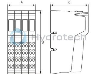
Dimensions
|
Type |
R-IB IL 24 DO 32/HD-PAC | |
|
A |
mm |
48.8 |
|
B |
mm |
120 |
|
C |
mm |
71.5 |
|
Note on dimensions |
The depth applies when using a support rail TH 35-7.5 (acc. to EN 60715). | |