

BOSCH REXROTH
R911170436
$917.60 USD
- BOSCH REXROTH
- Material:R911170436
- Model:R-IB IL AO 2/SF-PAC
Quantity in stock: 0
The Bosch Rexroth R-IB IL AO 2/SF-PAC (R911170436) is an advanced automation component specifically designed for integration into an Inline station to manage and output analog signals with high precision. This module is adept at providing analog voltage or current outputs, catering to a variety of industrial applications that require meticulous control and monitoring of analog parameters. The outputs of this module are capable of delivering signals in the ranges of 0...20 mA or 4...20 mA for current, and 0...10 V for voltage, ensuring compatibility with a broad spectrum of sensors and actuators. The R-IB IL AO 2/SF-PAC boasts an impressive resolution, which allows for fine-tuned signal processing and contributes to the overall reliability and accuracy of the system it's integrated into. This level of resolution ensures that even the most subtle changes in signal can be detected and acted upon, making this module ideal for critical processes where precision is paramount. Included with this module are essential accessories such as a connection plug and a labeling field, which facilitate easy installation and maintenance. The connection plug enables quick setup within the Inline station framework, while the labeling field provides a clear identification method to maintain organization within complex systems. This Bosch Rexroth analog output module stands out due to its ability to seamlessly interface with other components within an automation system while maintaining signal integrity and operational consistency. Its robust design tailored for demanding industrial environments ensures long-term durability and performance stability. Whether used in process control, manufacturing automation, or any other application requiring precise analog signal management, the R-IB IL AO 2/SF-PAC is engineered to deliver reliable functionality.
Inline connector
The modular, compact equipment configuration of the I/O systems from Rexroth offers you maximum flexibility for the cost-effective implementation of your individual machine concepts. The I/O modules have robust design and mechanics, are easy to use, have a quick reaction time and are quick to install – both in the control cabinet and in the field. Open communication standards allow you perfect integration of the I/O modules with maximum availability.
Unpacked Weight: 0.233 kg
This module is designed for use within an Inline station. It is used to output analog voltage or current signals. The signals are provided with a resolution of 16 bits.
| Data Sheet | Download Data Sheet |
| Manual | Download Manual |
| Air pressure (operation) | 70-106 kPa (up to 3,000 m above sea level) |
| Air pressure (storage / transport) | 70-106 kPa (up to 3,000 m above sea level) |
| Width | 48.8 |
| Productgroup ID | 4,6 |
| Height | 136.8 |
| International protection code | IP20 |
| Permissible air humidity (storage) | 10-95 |
| Voltage output signal | 0-10 V |
| Permissible air humidity (transport) | 10-95 |
| Number of channels | 2 |
| Output load voltage | |
| Current output signal | 0-20 mA 4-20 mA |
| Output load current | |
| Connection type | Zugfederanschluss |
| Connection techniques | 2-Leitertechnik |
| Depth | 72 |
| Weight | 0.233 |
| Ambient temperature (during operation) | -25-55 |
| Ambient temperature (storage and transport) | -25-85 |
| Conductor cross-section | Rigid: 0.2-1.5 mm²,Flexible: 0.2-1.5 mm²,AWG: 24 ... 16 |
General data
|
Type |
R-IB IL AO 2/SF-PAC | |
|
Color |
Gray | |
|
Weight 1) |
g |
190 |
|
Operating mode |
Process data mode with 2 words | |
|
Actuator connection type |
2-wire technology | |
|
Ambient temperature (operation) |
-25 °C ... +55 °C | |
|
Ambient temperature (storage/transport) |
-25 °C ... +85 °C | |
|
Permissible relative humidity (operation) |
10 % ... 95 % acc. to DIN EN 61131-2 | |
|
Permissible relative humidity (storage/transport) |
10 % ... 95 % acc. to DIN EN 61131-2 | |
|
Air pressure (operation) |
70 kPa ... 106 kPa (up to 3000 m above sea level) | |
|
Air pressure (storage/transport) |
70 kPa ... 106 kPa (up to 3000 m above sea level) | |
|
Protection type |
IP20 | |
|
Protection class |
III, IEC 61140, EN 61140, VDE 0140-1 | |
| 1) | Including plug |
Connection data
|
Type |
R-IB IL AO 2/SF-PAC | |
|
Designation |
Inline connection plug | |
|
Connection type |
Spring-cage connection | |
|
Conductor cross-section solid/flexible/AWG |
0.2 mm² ... 1.5 mm² 0.2 mm² ... 1.5 mm² 24 ... 16 |
|
Interface local bus
|
Type |
R-IB IL AO 2/SF-PAC | |
|
Connection type |
Inline data jumper | |
|
Transmission speed |
kBit/s |
500 |
|
Transfer physics |
Copper | |
Inline potentials/performance balance
|
Type |
R-IB IL AO 2/SF-PAC | |
|
Logic voltage UL |
V DC |
7.5 |
|
Typical current consumption from UL |
mA |
36 |
|
Maximum current consumption from UL |
mA |
45 |
|
Analog supply voltage UANA |
V DC |
24 |
|
Typical current consumption from UANA |
mA |
75 |
|
Maximum current consumption from UANA |
mA |
95 |
|
Typical power consumption total |
W |
2.1 |
Analog outputs
|
Type |
R-IB IL AO 2/SF-PAC | |||
|
Number of analog outputs 1) |
2 | |||
|
Signals/resolution in the process data bytes (quantization) |
For Inline |
Voltage 0 V ... 10 V |
0 V ... 10.837 V; 0.333 mV/LSB | |
|
Current 0 mA ... 20 mA |
0 mA ... 21.6764 mA; 0.667 μA/LSB | |||
|
Current 4 mA ... 20 mA |
4 mA ... 21.3397 mA; 0.553 μA/LSB | |||
|
For IB ST |
Voltage 0 V ... 10 V |
0 V ... 9.9975 V; 2.441 mV/LSB | ||
|
Current 0 mA ... 20 mA |
0 mA ... 19.9951 mA; 4.8828 μA/LSB | |||
|
Current 4 mA ... 20 mA |
4 mA ... 19.9961 mA; 3.906 μA/LSB | |||
|
Basic error limit |
% |
± 0.003 | ||
|
Output load voltage output |
kΩ |
≥ 2 | ||
|
Output load current output |
0 ... 500 | |||
|
Process data update of the assembly 2) |
ms |
< 1 | ||
| 1) | Configures dependent on terminal point used |
| 2) | Including conversion time of digital-analog converter |
Signal rise times
| 10 % ... 90 % | 0 % ... > 99 % | ||
|
Voltage output 0 V ... 10 V (typical data) |
|||
|
At no load |
µs |
44 | 72 |
|
Ohmic load RL = 2 kΩ |
µs |
46 | 74 |
|
Ohmic/capacitive load RL = 2 kΩ/CL = 10 nF |
µs |
47 | 95 |
|
Ohmic/capacitive load RL = 2 kΩ/CL = 220 nF |
µs |
79 | 350 |
|
Ohmic/inductive load RL = 2 kΩ/LL = 3.3 mH |
µs |
48 | 75 |
|
Power output 0 mA ... 20 mA (typical data) |
|||
|
Ohmic load RL = 500 Ω |
µs |
126 | 380 |
|
Ohmic/capacitive load RL = 500 Ω/CL = 10 nF |
µs |
140 | 425 |
|
Ohmic/capacitive load RL = 500 Ω/CL = 220 nF |
µs |
350 | 1200 |
|
Ohmic/inductive load RL = 500 Ω/LL = 3.3 mH |
µs |
110 | 368 |
|
Power output 4 mA ... 20 mA (typical data) |
|||
|
Ohmic load RL = 500 Ω |
µs |
140 | 508 |
|
Ohmic/capacitive load RL = 500 Ω/CL = 10 nF |
µs |
145 | 534 |
|
Ohmic/capacitive load RL = 500 Ω/CL = 220 nF |
µs |
380 | 1200 |
|
Ohmic/inductive load RL = 500 Ω/LL = 3.3 mH |
µs |
116 | 410 |
Tolerance and temperature behavior of outputs at TU = 25 °C
| Tolerance absolute, typical | Tolerance absolute, maximum | Tolerance relative, typical | Tolerance relative, maximum | |||
|
Output range |
0 V ... 10 V |
± 0.8 mV | ± 2 mV | ± 0.008 % | ± 0.02 % | |
|
0 mA ... 20 mA |
± 2 μA | ± 6 μA | ± 0.01 % | ± 0.03 % | ||
|
4 mA ... 20 mA |
± 2 μA | ± 6 μA | ± 0.01 % | ± 0.03 % | ||
Tolerance and temperature behavior of outputs at TU = -25 °C ... +55 °C
| Temperature coefficient maximum | Temperature coefficient typical | |||
|
Output range |
0 V ... 10 V |
ppm/K |
± 8 | ± 25 |
|
0 mA ... 20 mA |
ppm/K |
± 18 | ± 45 | |
|
4 mA ... 20 mA |
ppm/K |
± 18 | ± 45 | |
Additional tolerances under the influence of electromagnetic fields
|
Type |
R-IB IL AO 2/SF-PAC | ||
|
Type of electromagnetic interference |
Typical deviation from the measurement range end value ‒ relative |
||
|
Electro-magnetic fields Field strength 10 V/macc. to EN 61000-4-3/IEC 61000-4-3 |
Voltage output |
% |
< 0.1 |
|
Current output |
% |
< 0.1 | |
|
Line-fed disturbances III (test voltage 10 V)acc. to EN 61000-4-6/IEC 61000-4-6 |
Voltage output |
% |
< 0.1 |
|
Current output |
% |
< 0.3 | |
|
Fast transient disturbances (burst) supply 2 kV, output 1 kVacc. to EN 61000-4-4/IEC 61000-4-4 |
Voltage output |
Class A | |
|
Current output |
Class A | ||
|
Fast transient disturbances (burst) supply 4 kV, output 2 kVacc. to EN 61000-4-4/IEC 61000-4-4 |
Voltage output |
Class B | |
|
Current output |
Class B | ||
Protective devices
|
Type |
R-IB IL AO 2/SF-PAC | |
|
Transient protection on voltage and current outputs |
Yes | |
Programming data
|
Type |
R-IB IL AO 2/SF-PAC | |
|
ID code (hex) |
5B | |
|
ID code (dec) |
91 | |
|
Length code (hex) |
02 | |
|
Length code (dec) |
02 | |
|
Process data channel |
bits |
32 |
|
Input address room |
byte |
4 |
|
Output address room |
byte |
4 |
|
Parameter channel (PCP) |
byte |
0 |
|
Register length (bus) |
bits |
32 |
Fieldbus data telegram
|
Type |
R-IB IL AO 2/SF-PAC | |
|
Need for parameter data |
byte |
6 |
|
Need for configuration data |
byte |
5 |
Error messages to the higher-level control or computer system
|
Type |
R-IB IL AO 2/SF-PAC | |
|
Error message |
Upon failure or undershooting of the analog supply voltage UANA: Peripheral error message to the bus coupler | |
Electrical isolation/insulation of the voltage ranges
|
Type |
R-IB IL AO 2/SF-PAC | |
|
Common potentials |
||
|
24 V peripheral voltage, 24 V segment voltage and GND are on the same potential. FE represents a separate potential area. |
||
|
Separate potentials in the system of bus coupler/feed module and I/O module |
||
|
Test distance |
Test voltage | |
|
7.5 V supply (bus logic), 24 V supply UANA/peripherals |
500 V AC, 50 Hz, 1 min. | |
|
7.5 V supply (bus logic), 24 V supply UANA/function earth |
500 V AC, 50 Hz, 1 min. | |
|
24 V supply (peripherals)/function earth |
500 V AC, 50 Hz, 1 min. | |
Mechanical tests
|
Type |
R-IB IL AO 2/SF-PAC | |
|
Shock 1) |
15 g, 11 ms; 25 g, 6 ms; half sinusoidal shock pulse, 3 shocks per spatial direction | |
| 1) | Acc. to EN 60068-2-27/IEC 60068-2-27Deviation compared to DOK-CONTRL-ILSYSINS***-AW-DE-P |
|
Approvals |
|
The current approvals can be found at www.boschrexroth.com. |
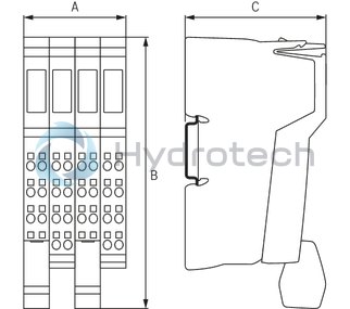
Dimensions
|
Type |
R-IB IL AO 2/SF-PAC | |
|
A |
mm |
48.8 |
|
B |
mm |
136.8 |
|
C |
mm |
72 |
|
Note on dimensions |
The depth applies when using a support rail TH 35-7.5 (acc. to EN 60715). | |