
BOSCH REXROTH
R901353720
$15,349.82 USD
- BOSCH REXROTH
- Material:R901353720
- Model:SYDFEN-3X/071R-VRB22U99-0000-A0R0VX
Quantity in stock: 0
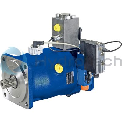
The Bosch Rexroth SYDFEN-3X/071R-VRB22U00-0000-A0R0VXX (R901353720) is an advanced hydraulic system component designed for precise electrohydraulic control. This triple pump combination is built upon the robust AVSO series, incorporating a swash plate axial piston variable displacement pump with integrated electronics for high-level performance. It features a nominal pressure of 280 bar and can withstand a maximum pressure that ensures reliability and longevity in demanding applications. The unit's capabilities include swivel angle control, pressure control, torque limitation, and master/slave functionality, which are essential for complex hydraulic systems. Its variable-speed communication options include both analog and CANopen protocols, making it highly adaptable to different system requirements. The SYDFEN-3X/071R-VRB22U00-0000-A0R0VXX is equipped with an inductive position transducer for precise valve position sensing, a swivel angle position sensor, and an optional pressure transducer to enhance its functionality. For pilot control and preload valve operations, this model uses the VTDFPn.X proportional valve as its pilot valve. The preload valve comes with an integrated pressure relief function (SYDZ), which is optional based on specific needs. The pump's digital OBE allows for seamless integration into various hydraulic circuits requiring precise control. Constructed with FKM seals and designed for clockwise rotation, the pump's geared shaft R endures rigorous operational conditions. Its electrical connection is facilitated by a Connector pole PE according to EN standards, and it operates at supply voltages of 24 VDC. The fastening conforms to ISO hole patterns for secure installation. With its comprehensive set of features including integrated electronics, proportional solenoid, precompression volume PCV, and various sensors for monitoring hydraulic functions, the Bosch Rexroth SYDFEN-3X/071R-VRB22U00-0000-A0R0VXX represents a sophisticated solution suitable for modern hydraulic systems where precision and adaptability are paramount.
Pump A10VSO BR32 with digital OBE
Triple pump combination, based on A10VSO series 32
Unpacked Weight: 49 kg
|
1 |
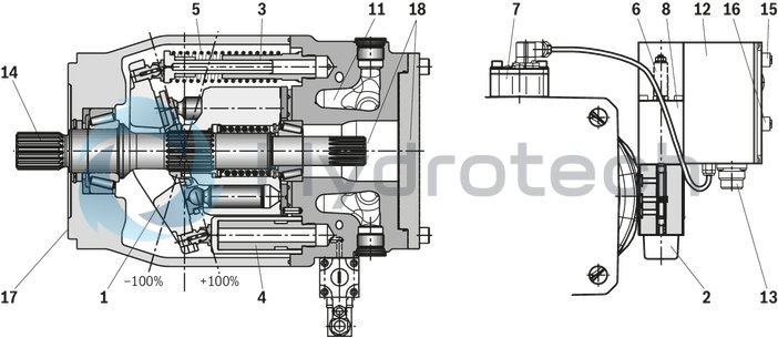
Swash plate |
|
2 |
Pilot control valve |
|
3 |
Counter piston |
|
4 |
Actuating piston |
|
5 |
Spring |
|
6 |
Inductive position transducer for valve position |
|
7 |
Swivel angle position sensor |
|
8 |
Proportional solenoid |
|
11 |
Pre-compression volume PCV |
|
12 |
Integral electronics |
|
13 |
Connector X1 |
|
14 |
Drive shaft |
|
15 |
Connector X2 for connection of the HM 20 pressure transducer cable version (only with actual pressure value input F) |
|
16 |
Mating connector X3 for connection of the CAN bus |
|
17 |
Connection flange |
|
18 |
Through-drive U.. closed with cover |
| Data Sheet | Download Data Sheet |
| Manual | Download Manual |
| Manual | Download Manual |
| Manual | Download Manual |
| Manual | Download Manual |
| Manual | Download Manual |
| Max. pressure | 280 |
| Shaft end | Geared shaft (R) |
| Electrical connection description | Connector 12-pole (11 + PE) according to EN 175201-804 |
| Speed min. | 250 |
| Productgroup ID | 9,10,11,12,13,14 |
| Controls | Integrated electronics |
| Electrical connector | Connector 12-pole (11 + PE) |
| Mounting flange | ISO 4-hole |
| Displacement type | variable |
| Direction of rotation | clockwise rotation |
| Supply voltage | 24 VDC |
| Weight | 49 |
| Seals | FKM |
| Connectivity | Digital |
| Hydraulic fluid | HLP |
|
01 |
02 |
03 |
04 |
05 |
06 |
07 |
08 |
09 |
10 |
11 |
12 |
13 |
14 |
15 |
16 |
17 |
||||
|
SYDFEn-3X |
/ |
071 |
– |
R |
22 |
U99- |
0000 |
– |
A |
0 |
A |
F |
L |
2 |
– |
* |
|
Pump of the SYDFE control system |
|||||||
|
Series |
|||||||
|
01 |
Variable speed control system with internal digital electronics (CANOpen fieldbus) |
SYDFEn-3X |
|||||
|
Pump combinations (see order example) |
SY2DFE.-2X, SY3DFE.-2X |
||||||
|
Size |
045 |
071 |
100 |
140 |
180 |
||
|
02 |
Displacement cm³ |
45 |
71 |
100 |
140 |
180 |
|
|
Direction of rotation looking at the drive shaft |
|||||||
|
03 |
Right |
● |
● |
● |
● |
● |
R |
|
Hydraulic fluid |
|||||||
|
04 |
Mineral oil according to DIN 51524 (HL/HLP) |
● |
● |
● |
● |
● |
V |
|
Drive shaft variant |
|||||||
|
05 |
Splined shaft profile SAE J 744 1) |
– |
– |
1 1/2’’ |
1 3/4’’ |
1 3/4’’ |
S |
|
Splined shaft profile SAE J 744 (higher through-drive torque) |
1’’ |
1 1/4’’ |
– |
– |
– |
R |
|
|
Connection flange according to ISO 30319-2 (4-hole) Ø centering in mm |
|||||||
|
06 |
ISO 4-hole |
125 |
160 |
180 |
180 |
180 |
B |
|
Subplate design |
|||||||
|
07 |
Without shock and vibration absorption (pre-compression volume, PCV) |
● |
● |
● |
● |
– |
22 |
|
With shock and vibration absorption (pre-compression volume, PCV; not with base pump variant 0487 or 0541 and not as high-speed version) |
– |
● |
● |
● |
● |
32 |
|
|
Design/through-drive |
|||||||
|
08 |
Universal through-drive U99 closed operationally safe with end cover at the factory; for components for the adaptation of more pump stages, see table Accessories for through-drives |
– |
● |
● |
● |
● |
U99- |
|
High speed version and universal through-drive U.. closed operationally safe with end cover at the factory; not with subplate 32; for components for the adaptation of more pump stages, see table Accessories for through-drives |
– |
● |
● |
● |
– |
U99S |
|
|
● |
– |
– |
– |
– |
U00S |
||
|
Base pump variant |
|||||||
|
09 |
Standard (internal pilot oil) |
● |
● |
● |
● |
0000 |
|
|
External supply |
● |
● |
– 2) |
● |
0479 |
||
|
External supply + regenerative operation |
● |
● |
● |
– |
0487 |
||
|
Regenerative operation without external supply |
● |
● |
– 2) |
– |
0541 |
||
|
Pilot and preload valve of the SYDFEn control system |
|||||||
|
Spool design |
|||||||
|
10 |
Standard |
A |
|||||
|
4-groove spool |
C |
||||||
|
Valve, installation orientation of integrated electronics, see comment on feature 11 |
|||||||
|
11 |
Radially to the pump axis |
0 |
|||||
|
folded 90° in the direction of the subplate |
2 |
||||||
|
Additional functions |
|||||||
|
12 |
Teach-in version for cyclic operation |
A |
|||||
|
Real-time version (speed calculation without teach-in) |
R |
||||||
|
Electronics assembly, option |
|||||||
|
13 |
Standard |
0 |
|||||
|
Actual pressure value input |
Plug-in connector |
C |
V |
E |
F |
||
|
14 |
Current input 4...20 mA |
X1 |
● |
C |
|||
|
Voltage input 0...10 V |
X1 |
● |
V |
||||
|
Voltage input 1...10 V |
X1 |
● |
E |
||||
|
Voltage input 0.5...5 V 3) |
X2 |
● |
F |
||||
|
Pressure transducer |
|||||||
|
15 |
HM 20-2X/315-F-C13-0,5, measurement range 315 bar (0.5...5 V) with connection cable 0.5 m for direct connection to X2 (only in connection with actual pressure value input F) |
● |
L |
||||
|
Without pressure transducer |
● |
● |
● |
● |
X |
||
|
Preload valve with integrated pressure limitation |
|||||||
|
16 |
Pressure limitation 200 bar (tolerance ± 8 bar) 4) |
1 |
|||||
|
Pressure limitation 250 bar (tolerance ± 10 bar) 4) |
2 |
||||||
|
Pressure limitation 300 bar (tolerance ± 12 bar) 4) |
3 |
||||||
|
Without preload valve |
X |
||||||
|
17 |
Further details in the plain text e. g. SO variant |
* |
|||||
| 1) | ANSI B92.1a-1976, 30° pressure angle, flat root, side fit, tolerance class 5. |
| 2) | Size 140 with subplate 22 (without PCV) is always suitable for regenerative operation; thus, the option is omitted. |
| 3) | With the SYDFEn control system with the additional function (feature 12 of the ordering codes) "Teach-in version for cyclic operation" and with analog interfaces, the switching input X2 cannot always be used as an actual pressure value input. It depends on the configuration. Please observe the notices in the operating instructions 30014-b. |
| 4) | The pressure relief function of the preload valve is designed for a maximum speed of 1800 rpm for NG140 and for a maximum speed of 1500 rpm for NG180. Higher speeds are available on request. |
|
● |
available |
|
- |
not available |
|
Note on feature 11: Valve, installation orientation of the integrated electronics |
|
|
Clockwise direction of rotation, installation orientation 0 |
Clockwise direction of rotation, installation orientation 2 |

|

|
Order example for single pump:
SYDFEn-3X/100R-VSB32U99-0479-A0A0XX
|
Order example for pump combinations: |
|||||
|
Double pump: |
|||||
|
Material numbers and/or type designations are to be connected by means of "+". |
|||||
|
Double pump |
2 |
||||
|
Size of the main pump |
100 |
||||
|
Size of the attachment pump or pump abbreviation if the attachment pump is not SYDFE (e. g. PGF) |
071 |
||||
|
Material number without "R9" for the main pump or type designation if material number is not known |
SYDFEn-3X/100R-VSB32U99-0000-A0A1VX3 |
||||
|
Pump combination, mounted with accessories |
Main pump (1st pump) |
+ |
Attachment pump (2nd pump) |
||
|
SY2DFEn-3X/100-071/01177440 |
+ |
01177441 |
|||
|
Material number without "R9" for the attachment pump or type designation if material number is not known |
SYDFEn-3X/071R-VRB32U99-0000-A0A1VX3 |
||||
|
Triple pump: |
Main pump (1st pump) |
+ |
Attachment pump (2nd pump) |
+ |
Attachment pump (3rd pump) |
|
SY3DFEn-3X/01128835 |
+ |
01151805 |
+ |
01128836 |
|
Example of name plate of a single pump
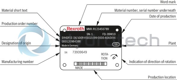
Notice:
For enquiries regarding the control system, material number, production order number, serial number, and date of production are necessary.
Accessories
Version 10/2015, enquire availability
|
Accessories |
Material number |
Data sheet |
|
Mating connector 12-pole for central connection X1 without cable (assembly kit) |
R900884671 |
08006 |
|
Mating connector 12-pole for central connection X1 with cable set 2 x 5 m |
R900032356 |
|
|
Mating connector 12-pole for central connection X1 with cable set 2 x 20 m |
R900860399 |
|
|
Pressure transducer HM 20-2X, measurement range 315 bar (4 ... 20 mA) |
R901342029 |
30272 |
|
Pressure transducer HM 20-2X, measurement range 315 bar (0.1 ... 10 V) |
R901342030 |
30272 |
|
Test device VT-PDFE-1-1X/V0/0 |
R900757051 |
29689-B |
|
Compact power supply unit VT-NE32-1X |
R90080049 |
29929 |
|
Converter USB serial for laptops without serial interface VT-ZKO-USB/S-1-1X/V0/0 |
R90106684 |
|
|
Cable for the connection of a Win-PED PC (RS232) at the interface X2, length 3 m |
R901156928 |
|
|
T connector for the simultaneous connection of a WIN-PED PC (RS232) and use of the T connector for the simultaneous connection of a WIN-PED PC (RS232) and use of the pressure transducer at connector X2 |
R901117164 |
|
|
Mating connector for interface X3, M12, straight, can be connected independently, 5-pole, shielded, A coded, cable diameter 6 ... 8 mm |
R901076910 |
|
|
Converter USB/CAN Bus for the connection of a computer to a CAN Bus system |
R901071963 |
|
|
Cable for the connection of CAN bus/X3 at CAN bus converter (D-Sub) |
R901152127 |
|
|
More accessories |
||
|
Accessories for through-drives |
See Accessories |
|
|
Torsionally flexible couplings for attachment to a standard electric motor |
See Accessories |
|
mechanisch und hydraulisch
|
Size |
45 | 71 | 100 | 140 | 180 | ||||
|
Displacement |
Vg max |
cm³ |
45 | 71 | 100 | 140 | 180 | ||
|
Max. speed |
Standard version |
no max |
rpm |
- | 1800 1) | 1800 2) | |||
|
High-speed version 2) |
no max |
rpm |
3000 | 2550 | 2300 | 2200 | - | ||
|
Minimum speed |
nmin |
rpm |
50 | ||||||
|
Max. flow (displacement) |
with max. speed (standard version) |
qv0 max |
l/min |
- | 128 | 180 | 252 | 324 | |
|
with max. speed (high-speed version) |
qv0 max |
l/min |
135 | 181 | 230 | 308 | - | ||
|
with nE = 1500 min-1 |
l/min |
67.5 | 106.7 | 150 | 210 | 270 | |||
|
Max. power (Δp = 280 bar) |
with max. speed (standard version) |
P0 max |
kW |
- | 59.7 | 84 | 118 | 151 | |
|
with max. speed (high-speed version) |
P0 max |
kW |
62.8 | 85 | 107 | 144 | - | ||
|
with nE = 1500 min-1 |
kW |
31 | 50 | 70 | 98 | 125 | |||
|
Max. torque (Δp = 280 bar, n0 max) |
Tmax |
Nm |
200 | 317 | 446 | 624 | 802 | ||
|
Maximum permissible drive torque |
Splined shaft S overall torque |
Ttotal |
Nm |
- | 1104 | 1620 | |||
|
Max. admissible through-drive torque |
TD |
Nm |
- | 778 | 1266 | ||||
|
Splined shaft R overall torque |
Ttotal |
Nm |
400 | 644 | - | ||||
|
Max. admissible through-drive torque |
TD |
Nm |
365 | 548 | - | ||||
|
Drive shaft load |

|
max. admissible axial force |
Fax max |
N |
1500 | 2400 | 4000 | 4800 | 800 |
|
max. admissible radial force |
Fq |
N 3) |
1500 | 1900 | 2300 | 2800 | 2300 | ||
|
Weight |
Pump without through-drive incl. pilot valve |
m |
kg |
32 | 49 | 71 | 75 | 80 | |
|
in addition, preload valve |
m |
kg |
3.3 | 6.3 | |||||
|
in addition, in case of external supply |
m |
kg |
2 | ||||||
|
Moment of inertia around drive axis |
JTW |
kg·m² |
0.0035 | 0.0087 | 0.0185 | 0.0276 | 0.033 | ||
|
Filling quantity of the housing |
V |
l |
1 | 1.6 | 2.2 | 3 | 2.7 | ||
|
Nominal pressure |
pnenn |
bar |
280 | ||||||
|
Maximum admissible operating pressure 4) |
pmax |
bar |
350 | ||||||
|
Operating pressure, min. (without load) |
with preload valve |
pmin |
bar |
≥ 1 | |||||
|
without preload valve |
pmin |
bar |
≥ 20 | ||||||
|
in case of external supply (20 bar) 5) |
pmin |
bar |
> 10 | ||||||
|
Admissible inlet pressure |
p |
bar |
1 ... 10 | 0.8 ... 10 | 1 ... 10 | ||||
|
bar |
- | 1 ... 10 | - | ||||||
|
Hydraulic fluid |
Mineral oil (HL, HLP) to DIN 51524 | ||||||||
|
Hydraulic fluid temperature range |
ϑ |
°C |
+70 | -20 … +70 | |||||
|
Maximum admissible degree of contamination of the hydraulic fluid according to ISO 4406 |
Class 18/16/13 (for particle size ≤ 4/6/14 μm) | ||||||||
| 1) | The values are applicable at an absolute pressure of 0.8 bar at suction opening S. |
| 2) | The value is applicable at an absolute pressure of 1.0 bar at suction opening S. |
| 3) | In case of higher radial forces, please consult us |
| 4) | See also data sheet 92714 |
| 5) | In continuous operation; in case of operation below 10 bar, observe the notes |
elektrisch
|
Size |
45 | 71 | 100 | 140 | 180 | |||
|
Operating voltage |
UB |
24 +40 % –5 % | ||||||
|
Operating range (short-time operation) |
Upper limit value |
UB(t)max |
V |
35 | ||||
|
Lower limit value |
UB(t)min |
V |
21 | |||||
|
Current consumption (in static control operation) |
Rated current |
Inom |
A |
0.6 | ||||
|
Maximum current |
Imax |
A |
1.25 | |||||
|
Inputs |
Actual pressure value input X1; |
U or I |
parameterizable: 0 ... 20 mA; 4 ... 20 mA; 0 ... 10 V; 0 … 5 V; 0.5 … 5 V; 0.1 ... 10 V; 1 ... 10 V | |||||
|
Analog current inputs, load 1) |
RB |
100 Ω | ||||||
|
Analog voltage inputs |
RE |
≥ 100 kΩ | ||||||
|
Digital inputs |
Logic 0 |
≤ 8 V | ||||||
|
Logic 1 |
≥ 14 V | |||||||
|
Outputs |
pactual / UOUT1 |
UO |
± 10 V | |||||
|
Imax |
2 mA | |||||||
|
αactual / UOUT2 |
UO |
± 10 V | ||||||
|
Imax |
2 mA | |||||||
|
Digital outputs |
Logic 0 |
Ua < 1 V | ||||||
|
Logic 1 |
Ua ≥ UB – 5 V; 10 mA (short-circuit-proof) | |||||||
|
Ambient temperature range at the pump |
ϑ |
°C |
0 … 50 | |||||
|
Storage temperature range (pump + electronics) |
ϑ |
°C |
0 … 70 | |||||
|
Electronics design |
Integrated in the pilot valve (OBE) | |||||||
|
Type of protection according to EN 60529 |
Pump incl. pilot valve |
IP65 with mounted and locked plug-in connectors | ||||||
| 1) | With configuration on current input: Maximum admissible input current 30 mA |
| 2) | With SYDFEC, SYDFEn and SYDFED, the outputs are parameterizable, for the condition as supplied, see electrical connection. |
Notice:
For information on the environment simulation testing for the areas EMC (electro-magnetic compatibility), climate and mechanical load, see data sheet 30630-U.
Control loop quality
Notes:
The specified values are only valid when using the system-related components specified in this data sheet. At pressures < 20 bar, higher tolerances have to be anticipated due to lower actuating forces.|
Swivel angle control |
Pressure control 1) |
|
|
Linearity tolerance |
≤ 1,0 % |
≤ 1,5 % (≤ 1,0 % 2)) |
|
Temperature error |
≤ 0,5 % / 10 K |
≤ 0,5 % / 10 K |
|
Hysteresis |
≤ 0,2 % |
≤ 0,2 % |
|
Repetition accuracy |
≤ 0,2 % |
≤ 0,2 % |
| 1) | Without considering the pump pulsation. |
| 2) | Using the integrated calibration function. |
For applications outside these parameters, please consult us!
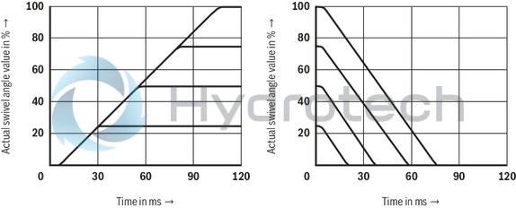
Transition function with pressure command value step with spool design "A"
The specified curve shapes and control times refer to a drive speed of 1500 rpm and are only reached with an optimization of the pressure controller.
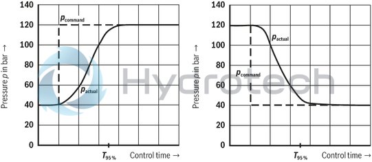
T95% in ms with a connected hydraulic fluid volume (lines and actuators)
|
Hydraulic fluid volume in l |
T95% in ms |
|
< 5 |
150 |
|
5 – 10 |
200 |
|
15 ... 25 |
250 |
For pressures up to 40 bar, the values of the response times are greater.
Transition function with swivel angle command value step with spool design "A"
NG45, 71 p = 50 bar
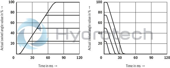
Size 100 p = 50 bar
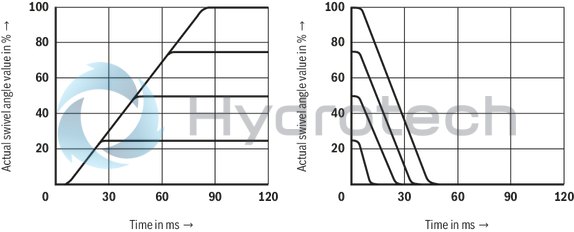
Size 140 p = 50 bar

NG180 p = 50 bar
Schematic diagram: Actuating system supplied internally
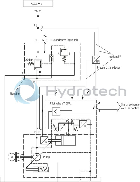
| 1) |
When using the pressure transducer HM 20 cable version: Installation in P (pump) or MP1 (preload valve) in connection with electronic version "Actual pressure value input F". When using an external pressure transducer: Installation in the P1 line (preferably close to the actuator) and electrical connection via the central connector. When using a preload valve, the pressure transducer is to be connected to P1 or MP1. |
Schematic diagram: Actuating system supplied externally
The representation shows an example with integrated electronics.
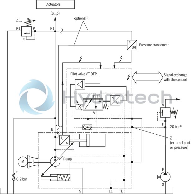
| 1) | The use of an anti-cavitation valve (check valve with 0.2 bar spring) is essential in order to prevent dry-running in the error case. |
|
2) |
Pressure transducer |
Mounting options |
Comment |
|
HM 20-2X/315-F-C13-0.5 (cable version) |
P |
Only in connection with actual pressure value input "F" |
|
|
HM 20-2X/...-.-K35 (connector version) |
P1 |
Preferably close to the actuator |
| 3) Maximum pressure limitation must be provided by the customer! | |
| 4) Observe upper limit for external pilot oil pressure! (see operating instructions), recommendation: 20 bar absolute. |
Important notes on external supply:
In the case of an actuating system with external supply, the pump adjustment will - in case of voltage failure - not switch to zero stroke but to the negative stop (displacement of 100 % flow from the system to the tank). With an active fault message, it is imperative that the machine control reacts (e. g. switching off the drive motor of the pump, interrupting the external supply of the actuating system). The command values for pressure and flow must always be greater than zero (pcommand ≥ 3 bar, αcommand ≥ 5 %) as due to drift or tolerances, there is no exact "zero" pressure or "zero" swivel angle. Under unfavorable conditions, smaller command value presettings can lead to cavitation. The actual pressure value must not be less than 10 bar for more than 10 minutes (lubrication).
Allocation of connector or mating connector and cable set
|
Pin |
Signal |
Description |
Signal direction |
Type of signal |
Allocation in the cable set (accessories) |
|
|
1 |
+ UB |
Voltage supply |
IN |
24 V DC |
1 |
Supply line 3 x 1.0 mm2 |
|
2 |
0 V = L0 |
Reference potential for the voltage supply |
– |
2 |
||
|
PE |
Earth |
Earthing connection for the electronics |
– |
green/yellow |
||
|
3 |
Fault |
Signals faults, e.g. cable break command / actual values, controller monitoring (logic 0 = error) |
OUT |
logic 24 V |
white |
Supply line 10 x 0.14 mm2 shielded (one end of the shield must be connected to the control!) |
|
4 |
M0 |
Reference potential for analog signals |
– |
yellow |
||
|
5 |
AI2 |
Analog input AI2 |
IN |
analog ±10 V |
green |
|
|
6 |
UOUT2 |
Analog output |
OUT |
analog ±10 V |
Violet |
|
|
7 |
AI1 |
Analog input AI1 |
IN |
analog 0...10 V |
pink |
|
|
8 |
UOUT1 |
Analog output |
OUT |
analog ±10 V |
red |
|
|
9 |
DI1 |
Digital input DI1 |
IN |
logic 24 V |
brown |
|
|
10 |
Actual pressure value H |
Actual pressure value input: Signal level depends on feature 14 of the ordering code |
IN |
analog |
black |
|
|
11 |
Actual pressure value L |
– |
analog |
blue |
||
|
n.c. |
gray |
|||||
X2: Serial interface RS232 and a switchable digital input/pressure transducer for HM 20
HM 20-2X/315-F-C13-0,5 (cable version) (mating connector M12)
|
Pin |
Signal input |
Pin |
Signal CAN |
|
1 |
OUT, +UB |
2 |
RxD |
|
3 |
Reference L0 |
||
|
4 |
Analog input 0.5 ... 5 V for HM 20 or digital input 0 V low, 10 V high 1) Depending on additional function (feature 12 of the ordering code), Factory setting: ▶ Teach-in version: Digital input "Variable-speed operation on, S1" ▶ Real-time version: Input as analog input for pressure transducer HM 20 |
5 |
TxD |
X3: Connection CAN bus and digital input 2 (DI2) (connector M12)
|
Pin |
Signal input |
Pin |
Signal CAN |
|
1 |
n.c. |
3 |
CAN GND |
|
2 |
IN, digital IN2 (DI2) Depending on additional function (feature 12 of the ordering code), Factory settings: ▶ Teach-in version: Start Teach-In, S2 ▶ Real-time version: Manual speed presetting active, speed is applied according to the real-time operation status and the setting of the R parameters. |
4 |
CAN-HIGH |
|
5 |
CAN-LOW |
| 1) | For valves with date of manufacture including 2013 max. 12 V. For valves after date of production 2014 max. UB. |
Integrated electronics with installation orientation 0
The dimensions of the base pump (axial piston variable displacement pump A10VSO.../32) are contained in data sheet 92714.
NG45 … 180
(Valve mounting direction "0"; shaft design "S" or "R" with universal through-drive “U..")
Dimensions in mm
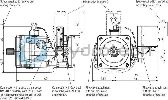
(representation size 100)
|
Size |
Dimensions with base pump variant "0479" or "0487" |
Max. length |
|||||||||
|
A1 |
A3 1) |
A4 |
A5 |
A6 |
A6 I |
A6 II |
A8 I |
A8 II |
A8 III |
A9 |
|
|
mm |
mm |
mm |
mm |
mm |
mm |
mm |
mm |
mm |
mm |
mm |
|
| 45 | 134 | 218 | 158 | 63 | 206 | 91 | 115 | 253 | 145 | 125 | 266 |
| 71 | 146 | 226 | 158 | 63 | 254 | 104 | 150 | 261 | 159 | 150 | 301 |
| 100 | 151 | 237 | 158 | 63 | 247 | 100 | 147 | 272 | 164 | 150 | 360 |
| 140 | 162 | 250 | 158 | 63 | 257 | 110 | 147 | 285 | 182 | 150 | 377 |
| 180 | 162 | 250 | 158 | 63 | 257 | 110 | 147 | 285 | 182 | 150 | 387 |
| 1) | Dimension with base pump variant 0000 or 0541 |
Integrated electronics with installation orientation 2
The dimensions of the base pump (axial piston variable displacement pump A10VSO.../32) are contained in data sheet 92714.
NG45 … 180
(Valve mounting direction “2"; shaft design "S" or "R" with universal through-drive “U..”)
Dimensions in mm
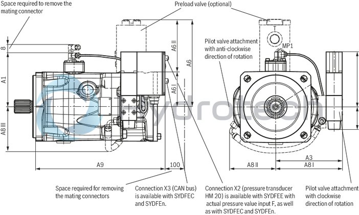
(representation size 100)
|
Size |
Dimensions with base pump variant "0479" or "0487" |
Max. length |
|||||||||
|
A1 |
A3 1) |
A4 |
A5 |
A6 |
A6 I |
A6 II |
A8 I |
A8 II |
A8 III |
A9 |
|
|
mm |
mm |
mm |
mm |
mm |
mm |
mm |
mm |
mm |
mm |
mm |
|
| 45 | 134 | 138 | 158 | 63 | 206 | 91 | 115 | 173 | 145 | 125 | 287 |
| 71 | 146 | 146 | 158 | 63 | 254 | 104 | 150 | 181 | 159 | 150 | 316 |
| 100 | 151 | 157 | 158 | 63 | 247 | 100 | 147 | 192 | 164 | 150 | 372 |
| 140 | 162 | 170 | 158 | 63 | 257 | 110 | 147 | 205 | 182 | 150 | 382 |
| 180 | 162 | 170 | 158 | 63 | 257 | 110 | 147 | 205 | 182 | 150 | 392 |
| 1) | Dimension with base pump variant 0000 or 0541 |
Combination pumps BR32
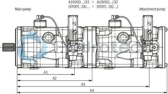
|
Attachment pump |
Main pump |
|||||||||||||||||||
|
A10VSO 45 |
A10VSO 71 |
A10VSO 100 |
A10VSO 140 |
A10VSO 180 |
||||||||||||||||
|
A1 |
A2 |
A3 |
A4 |
A1 |
A2 |
A3 |
A4 |
A1 |
A2 |
A3 |
A4 |
A1 |
A2 |
A3 |
A4 |
A1 |
A2 |
A3 |
A4 |
|
|
A10VSO 18 BR31 |
184 |
264 |
409 |
459 |
217 |
299 |
444 |
494 |
275 |
360 |
505 |
555 |
275 |
377 |
522 |
572 |
285 |
387 |
532 |
582 |
|
A10VSO 28 BR31 |
184 |
264 |
428 |
470 |
217 |
299 |
463 |
505 |
275 |
360 |
524 |
566 |
275 |
377 |
541 |
583 |
285 |
387 |
551 |
593 |
|
A10VSO 45 BR31 |
217 |
299 |
483 |
523 |
275 |
360 |
544 |
584 |
275 |
377 |
561 |
601 |
285 |
387 |
571 |
611 |
||||
|
A10VSO 45 BR32 |
184 |
264 |
448 |
530 |
217 |
299 |
483 |
565 |
275 |
360 |
544 |
626 |
275 |
377 |
561 |
643 |
285 |
387 |
571 |
653 |
|
A10VSO 71 BR32 |
217 |
299 |
516 |
600 |
275 |
360 |
577 |
661 |
275 |
377 |
594 |
678 |
285 |
387 |
604 |
688 |
||||
|
A10VSO 100 BR32 |
275 |
360 |
635 |
720 |
275 |
377 |
652 |
737 |
285 |
387 |
662 |
747 |
||||||||
|
A10VSO 140 BR32 |
275 |
377 |
652 |
754 |
285 |
387 |
662 |
764 |
||||||||||||
|
A10VSO 180 BR32 |
285 |
387 |
672 |
774 |
||||||||||||||||
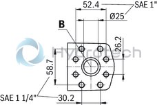
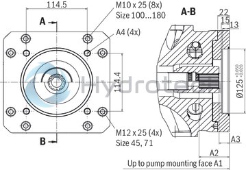
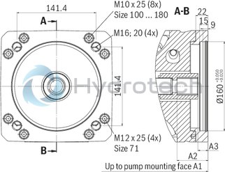
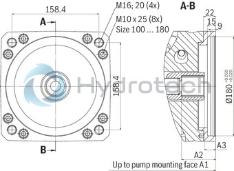
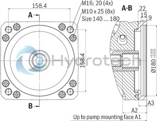
Ports
|
Size |
45 |
71 |
100 |
140 |
180 |
||
|
B: |
Working line (SAE J518) 1) |
||||||
|
Size |
1″ |
1″ |
1 1/4″ |
1 1/4″ |
1 1/4″ |
||
|
Mounting thread (DIN 13) |
M10 x 1.5; 17 deep |
M14 x 2; 19 deep |
|||||
|
Peak pressure 2) |
bar |
350 |
|||||
|
S: |
Suction line (SAE J518) 1) |
||||||
|
Size |
1 1/2″ |
2″ |
2 1/2″ |
2 1/2″ |
2 1/2″ |
||
|
Mounting thread (DIN 13) |
M12 x 1.75; 20 deep |
M12 x 1.75; 17 deep |
|||||
|
Peak pressure 2) |
bar |
10 |
|||||
| 1) | Dimensions according to SAE J518 only, metric mounting thread deviating from the standard. |
| 2) | Application-specific short-time pressure peaks may occur. Please observe when selecting measuring devices and fittings. Specified pressures are in bar absolute. |
Notes regarding size 71:
With pressure connection “B” of size 71, two SAE mounting connections rotated by 90° are available. SAE 1 1/4″ standard pressure series, 3000 psi , for pressures up to 250 bar or SAE 1″ standard pressure series, 5000 psi, for pressures up to 350 bar. For operating pressures exceeding 250 bar, the pressure flange SAE 1” must be used.Dimensions in mm
Before determining your design, please request a binding installation drawing.
U52
Flange ISO 3019-1-82-2
Hub for splined shaft according to ANSI B92.1a-1996
3/4″ 11T 16/32DP 1)
(SAE J744 - 19-4 (A-B))
Dimensions in mm
|
NG |
A1 |
A2 |
A3 |
|
mm |
mm |
mm |
|
| 45 | 264 | 38.7 | 18.5 |
| 71 | 299 | 38 | 17.5 |
| 100 | 360 | 38 | 17.5 |
| 140 | 377 | 38 | 17.5 |
| 180 | 387 | 38 | 17.5 |
| 1) 30° pressure angle, flat root, side fit, tolerance class 5 |
UB3
Flange ISO 3019-2 - 100B2HW
Hub for splined shaft according to ANSI B92.1a-1996
7/8″ 13T 16/32DP 1)
(SAE J744 - 22-4 (B))
Dimensions in mm
|
NG |
A1 |
A2 |
A3 |
|
mm |
mm |
mm |
|
| 45 | 264 | 41.6 | 18 |
| 71 | 299 | 41 | 16.5 |
| 100 | 360 | 41 | 16.5 |
| 140 | 377 | 41 | 16.5 |
| 180 | 387 | 41 | 16.5 |
| 1) 30° pressure angle, flat root, side fit, tolerance class 5 |
UB4
Flange ISO 3019-2 - 100B2HW
Hub for splined shaft according to ANSI B92.1a-1996
1″ 15T 16/32DP 1)
(SAE J744 - 25-4 (B-B))
Dimensions in mm
|
NG |
A1 |
A2 |
A3 |
||
|
mm |
mm |
mm |
|||
| 45 | 264 | - | Upon request | - | Upon request |
| 71 | 299 | 45.9 | - | 16.9 | - |
| 100 | 360 | 45.9 | - | 16.9 | - |
| 140 | 377 | 45.9 | - | 16.9 | - |
| 180 | 387 | 45.9 | - | 16.9 | - |
| 1) 30° pressure angle, flat root, side fit, tolerance class 5 |
UE1
Flange ISO 3019-2 - 125 4-hole
Hub for splined shaft according to ANSI B92.1a-1996
1″ 15T 16/32DP 1)
(SAE J744 - 25-4 (B-B))
Dimensions in mm
|
NG |
A1 |
A2 |
A3 |
||
|
mm |
mm |
mm |
|||
| 45 | 264 | - | Upon request | - | Upon request |
| 71 | 299 | 45.9 | - | 16.9 | - |
| 100 | 360 | 45.9 | - | 16.9 | - |
| 140 | 377 | 45.9 | - | 16.9 | - |
| 180 | 387 | 45.9 | - | 16.9 | - |
| 1) 30° pressure angle, flat root, side fit, tolerance class 5 |
UB8
Flange ISO 3019-2 - 160B4HW
Hub for splined shaft according to ANSI B92.1a-1996
1 1/4″ 14T 12/24DP 1)
(SAE J744 - 32-4 (C))
Dimensions in mm
|
NG |
A1 |
A2 |
A3 |
|
mm |
mm |
mm |
|
| 71 | 299 | 55.4 | 17.9 |
| 100 | 360 | 55.4 | 17.9 |
| 140 | 377 | 55.4 | 17.9 |
| 180 | 387 | 55.4 | 17.9 |
| 1) 30° pressure angle, flat root, side fit, tolerance class 5 |
UB9
Flange ISO 3019-2 - 180B4HW
Hub for splined shaft according to ANSI B92.1a-1996
1 1/2″ 17T 12/24DP 1)
(SAE J744 - 38-4 (C-C))
Dimensions in mm
|
NG |
A1 |
A2 |
A3 |
|
mm |
mm |
mm |
|
| 100 | 360 | 61.9 | 20.4 |
| 140 | 377 | 61.9 | 20.4 |
| 180 | 387 | 61.9 | 20.4 |
| 1) 30° pressure angle, flat root, side fit, tolerance class 5 |
UB7
Flange ISO 3019-2 - 180B4HW
Hub for splined shaft according to ANSI B92.1a-1996
1 3/4″ 13T 8/16DP 1)
(SAE J744 - 44-4 (D))
Dimensions in mm
|
NG |
A1 |
A2 |
A3 |
|
mm |
mm |
||
| 140 | 377 | 75 | Upon request |
| 180 | 387 | 75 | Upon request |
| 1) 30° pressure angle, flat root, side fit, tolerance class 5 |
U01
Flange ISO 3019-1-82-2
Hub for splined shaft according to ANSI B92.1a-1996
5/8″ 9T 16/32DP 1)
(SAE J744 - 16-4 (A))
Dimensions in mm
|
NG |
A1 |
A2 |
A3 |
||
|
mm |
mm |
mm |
|||
| 45 | 264 | - | Upon request | - | Upon request |
| 71 | 299 | 31.8 | - | 19.3 | - |
| 100 | 360 | 31.8 | - | - | Upon request |
| 140 | 377 | 31.8 | - | - | Upon request |
| 180 | 387 | 31.8 | - | - | Upon request |
| 1) 30° pressure angle, flat root, side fit, tolerance class 5 |
U68
Flange ISO 3019-1-101-2
Hub for splined shaft according to ANSI B92.1a-1996
7/8″ 13T 16/32DP 1)
(SAE J744 - 22-4 (B))
Dimensions in mm
|
NG |
A1 |
A2 |
A3 |
|
mm |
mm |
mm |
|
| 45 | 264 | 41.5 | 18.2 |
| 71 | 299 | 41 | 16.5 |
| 100 | 360 | 41 | 16.5 |
| 140 | 377 | 41 | 16.5 |
| 180 | 387 | 41 | 16.5 |
| 1) 30° pressure angle, flat root, side fit, tolerance class 5 |
U04
Flange ISO 3019-1-101-2
Hub for splined shaft according to ANSI B92.1a-1996
1″ 15T 16/32DP 1)
(SAE J744 - 25-4 (B-B))
Dimensions in mm
|
NG |
A1 |
A2 |
A3 |
||
|
mm |
mm |
mm |
|||
| 45 | 264 | - | Upon request | - | Upon request |
| 71 | 299 | 45.9 | - | 16.9 | - |
| 100 | 360 | 45.9 | - | 16.9 | - |
| 140 | 377 | 45.9 | - | 16.9 | - |
| 180 | 387 | 45.9 | - | 16.9 | - |
| 1) 30° pressure angle, flat root, side fit, tolerance class 5 |
U24
Flange ISO 3019-1-127-2
Hub for splined shaft according to ANSI B92.1a-1976
1 1/2″ 17T 12/24DP 1)
(SAE J744 - 38-4 (C-C))
Dimensions in mm
|
NG |
A1 |
A2 |
A3 |
|
mm |
mm |
mm |
|
| 100 | 360 | 61.9 | 20.4 |
| 140 | 377 | 70.5 | 10.5 |
| 180 | 387 | 70.5 | 10.5 |
| 1) 30° pressure angle, flat root, side fit, tolerance class 5 |
Always shield command and actual value cables. The distance to aerial lines or radios must be at least 1 m. Do not lay signal lines close to power lines. For amending notes on the SYDFE control system, see the operating instructions (see section "More information about this control system").
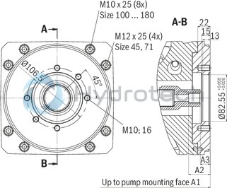
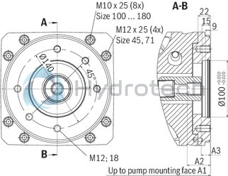
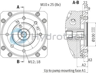
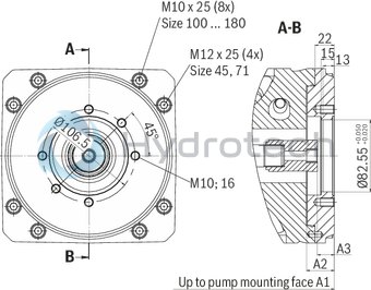
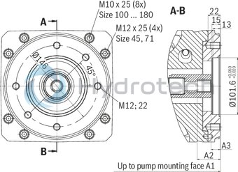
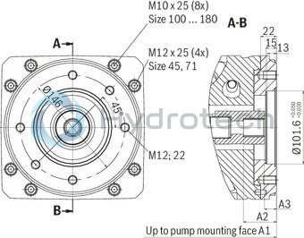
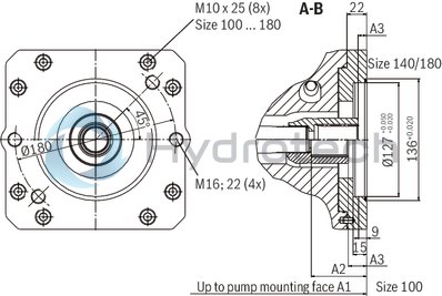
Accessories for through-drives
With the introduction of A10VSO, series 32, a so-called universal through-drive for combining several pump stages is used. The required components can be seen from the following table and are to be ordered separately. Flange kit and hub are included in the mounting kit.
The following conditions apply to the attachment pumps listed in the table:
SYDFE and A10VSO with shaft S or R PGH with shaft R, flange U2, see data sheet 10223 PGF3 with shaft J, flange U2, see data sheet 10213 AZPF with shaft R, front cover R, see data sheet 10089Also note that the flange and the through-drive (see type key pump) are identical. Check in the current data sheet of the gear pump whether the shaft ends have the specified dimensions.
|
Components universal through-drive |
Main pump SYDFE..-3X/..U.. |
Attachment pump |
||||||
|
NG45 |
NG71 |
NG100 |
NG140 |
Size and type |
Through-drive Centering Hub |
Flange designation |
||
|
Mounting kit |
R902496472 |
R902447036 |
R902447038 |
R902447039 |
NG18 |
SYDFE..-2X/ |
U52 |
ISO 3019-1-82-2 |
|
Flange kit |
R902514629 |
R902446836 |
R902446850 |
R902446850 |
||||
|
Hub |
R902436100 |
R902436200 |
R902436201 |
R902436202 |
||||
|
Mounting kit |
R902492531 |
R902446997 |
R902446999 |
R902447000 |
NG28 |
UB3 |
ISO 3019-2 |
|
|
Flange kit |
R902492530 |
R902446808 |
R902446809 |
R902446809 |
||||
|
Hub |
R902436084 |
R902436083 |
R902436101 |
R902436102 |
||||
|
Mounting kit |
R902447002 |
R902447004 |
R902447005 |
NG45 |
UB4 |
ISO 3019-2 |
||
|
Flange kit |
R902446808 |
R902446809 |
R902446809 |
|||||
|
Hub |
R902436104 |
R902436105 |
R902436204 |
|||||
|
Mounting kit |
R902510125 |
R902492823 |
R902488254 |
R902491915 |
NG45 |
SYDFE..-3X/..U.. |
UE1 |
ISO 3019-2 |
|
Flange kit |
R902511813 |
R902492824 |
R902446813 |
R902446813 |
||||
|
Hub |
R902436103 |
R902436104 |
R902436105 |
R902436204 |
||||
|
Mounting kit |
R902447015 |
R902447017 |
R902447018 |
NG71 |
UB8 |
ISO 3019-2 |
||
|
Flange kit |
R902446816 |
R902446817 |
R902446817 |
|||||
|
Hub |
R902436085 |
R902436086 |
R902436106 |
|||||
|
Mounting kit |
R902447023 |
R902447024 |
NG100 |
UB9 |
ISO 3019-2 |
|||
|
Flange kit |
R902446820 |
R902446820 |
||||||
|
Hub |
R910943565 |
R910943555 |
||||||
|
Mounting kit |
R902447027 |
NG140 |
UB7 |
ISO 3019-2 |
||||
|
Flange kit |
R902446820 |
|||||||
|
Hub |
R910932172 |
|||||||
|
Mounting kit |
R902496467 |
R902447031 |
R902447033 |
R902447034 |
PGF2, PGH2, PGH3, AZPF |
U01 |
ISO 3019-1-82-2 |
|
|
Flange kit |
R902514629 |
R902446836 |
R902446850 |
R902446850 |
||||
|
Hub |
R902435448 |
R910943545 |
R910943560 |
R910943551 |
||||
|
Mounting kit |
R902496477 |
R902447041 |
R902447043 |
R902447044 |
PGF3 |
U68 |
ISO 3019-1-101-2 |
|
|
Flange kit |
R902511150 |
R902446837 |
R902446851 |
R902446851 |
||||
|
Hub |
R902436084 |
R902436083 |
R902436101 |
R902436102 |
||||
|
Mounting kit |
R902496482 |
R902447046 |
R902447048 |
R902447049 |
PGH4 |
U04 |
ISO 3019-1-101-2 |
|
|
Flange kit |
R902446837 |
R902446851 |
R902446851 |
|||||
|
Hub |
R902436104 |
R902436105 |
R902436204 |
|||||
|
Mounting kit |
R902479709 |
R902463283 |
PGH5 |
U24 |
ISO 3019-1-127-2 |
|||
|
Flange kit |
R902446852 |
R902446852 |
||||||
|
Hub |
R902436369 |
R910943555 |
||||||
| 1) | ANSI B92.1a-1976, 30° pressure angle, flat root, side fit, tolerance class 5. A mounting kit includes the flange kit and hub; a flange kit includes the flange, seals and mounting materials. |
Combinations are only possible with shaft ends according to SAE J744
Torsionally flexible couplings for attachment to a standard electric motor
|
Motor |
SYDFE.-3X |
||||
|
Frame size/characteristic |
Shaft diameter in mm |
NG45 Shaft R, 1" |
NG71 Shaft S or R, 1 1/4" |
NG100 Shaft S, 1 1/2" |
NG140/180 Shaft S, 1 3/4" |
|
100/0 |
28 |
R901038017 |
|||
|
132/0 |
38 |
R900772898 |
|||
|
160/0 |
42 |
R900994283 |
R900228413 |
||
|
180/0 |
48 |
R900062159 |
R900240468 |
R900242567 |
|
|
200/0 |
55 |
R901038025 |
R901038021 |
R901104689 |
R901038048 |
|
225/0 |
60 |
R901066409 |
R900228375 |
R901050508 |
R900988121 |
|
250/0 |
65 |
R900988348 |
R900986404 |
R901046864 |
R900708084 |
|
280/0 |
75 |
R900218487 |
R901055216 |
R901052451 |
|
|
315/0 |
80 |
R901046894 1) |
R901041730 1) |
||
|
315/1 |
80 |
R901046885 |
|||
| 1) | Up to 40 °C |
Mating connectors for valves with round connector, 11-pole + PE
12P N11
Mating connectors for valves with round connector, 11-pole + PE
12P N11
For valves with round connector according to EN 175201-804, 11-pole + PEData sheet
Spare parts & repair
Mating connectors for valves with round connector, 11-pole + PE, shielded, with assembled connection line
12P N11 +

Mating connectors for valves with round connector, 11-pole + PE, shielded, with assembled connection line
12P N11 +
For valves with round connector according to EN 175201-804, 11-pole + PEData sheet
Spare parts & repair