

BOSCH REXROTH
R901009038
$1,754.93 USD
- BOSCH REXROTH
- Material:R901009038
- Model:VT-VRPA1-100-1X/V0/0
Quantity in stock: 2
The Bosch Rexroth VT-VRPA1-100-1X/V0/0 (R901009038) is a sophisticated valve amplifier designed to control solenoid valves with position feedback, specifically for DBETR and FRE type valves. Its quick installation and analog command value connectivity, ranging from 0 to 10 V, make it a versatile component in hydraulic systems. The product features a design card form factor and includes a pin connector plug in form D for electrical connections. This amplifier is equipped with a ramp function that processes step-shaped input signals into ramp-shaped output signals, with adjustable time constants for both upward and downward ramps. The ramp times can be set through front plate potentiometers or externally via jumpers, allowing for flexibility in response to system demands. Additionally, the VT-VRPA1-100-1X/V0/0 includes an enable input that activates the output stage and I controller when supplied with a signal greater than 15 V, indicated by a yellow LED. It also offers reverse polarity protection for its operating voltage and outputs for both command value and actual value signals. The unit's position sensing capabilities are facilitated by an oscillator driving an inductive position transducer, which must be connected as a throttle circuit with mid-sensing. The actual valve spool position is represented by the actual value signal, which is output inversely compared to the command value. Bosch Rexroth's commitment to precision is evident in this product's PID controller optimization for DBETR and FRE valves, ensuring accurate control based on the comparison of position command values against actual position values. The VT-VRPA1-100-1X/V0/0 also provides robust power supply features, LED indication for operational readiness, and options for external time potentiometer connection. This makes it an essential component for hydraulic system operators seeking precise control over their valve operations.
Valve amplifier for control valves with 1 solenoid with position feedback
Adjusted to valves. Short commissioning time.
Unpacked Weight: 0.20091 kg
Limitation and position controller
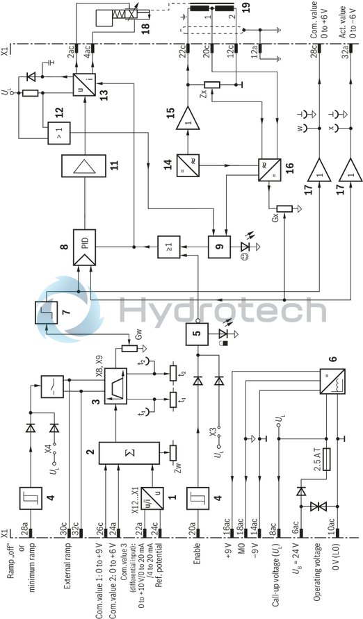
From the output of the ramp generator [3], the command value voltage reaches the "Gw" potentiometer which is accessible through the front plate and serves as attenuator. It can also be used to set the maximum flow of the valve. The downstream limiter [7] limits the command value to 105 % or –5 % (e.g. at excessive command value voltage or by adjustment of the potentiometer for zero point "Zw" and basic value "Gw") to prevent the valve spool from hitting the mechanical end positions. The output signal of the limiter [7] is the position command value which is supplied to the PID controllers [8] and via an output stage [17] also to measuring socket "w" on the front plate of the card as well as to port 28c at the connector strip X1 (command value after ramp and limiter). A voltage of +6 V at command value measuring socket "w" corresponds to a command value of +100 %. The PID controller has been especially optimized for DBETR and FRE valves. In the controller, the position command value and the actual position value are compared; in case of a difference, a corresponding control output is forwarded to the current output stage [13] the output signal of which controls the proportional solenoid of valve.
Position sensing
The position transducer electronics consist of an oscillator [14] with downstream driver [15] for controlling the inductive position transducer and a demodulator [16] for analyzing the position transducer signal (actual value). The oscillator frequency is approx. 2.5 kHz. The inductive position transducer must be connected as throttle circuit with mid sensing. The position transducer electronics have been adjusted at the factory. Very long or capacitive position transducer lines may require readjustment of the zero point (via potentiometer "Zx"). The actual value (corresponds to the valve spool position) can be measured at the actual value measuring socket.
Notice:
The actual value signal is output in inverted form as compared to the command value. A path of 100 % corresponds to –6 V at the actual value measuring socket and at port 32a of the connector strip X1.
Enable input
With a signal of > 10 V at enable input 20a, the output stage and I controller are enabled (indication by the yellow LED at the front plate). By setting jumper X3, these are independently and permanently enabled by the signal at the enable input. The switching input will then be ineffective.
[ ] = Assignment to the block diagram
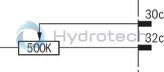
When using an external time potentiometer, the internal potentiometers for the ramp times must be set to maximum (voltages at the "t1" and "t2" measuring sockets approx. 20 mV). The maximum ramp time is reduced as the resistance value of the external potentiometer is switched in parallel to that of the internal potentiometer (approx. 500 kΩ). In this case, the ramp times for upwards and downwards ramp cannot be set separately.
By applying a voltage >10 V to the "Ramp off" switching input or setting the plug-in jumper X4, the ramp time is set to its minimum value (approx. 15 ms). The switching input will then be ineffective. The minimum value is then valid for both directions.
Calculation of the ramp times
Jumper X9 plugged (ramp time "short")

Jumper X8 plugged (ramp time "long")

The following applies:
U = Voltage in volt at measuring socket "t1" or "t2"
t = Ramp time in seconds for upwards and downwards ramp
Ramp function
The down-stream ramp generator [3] generates a ramp-shaped output signal from a given step-shaped input signal. The time constants of the output signal (ramp times) can be adjusted using the "t1" (upwards ramp) and "t2" (downwards ramp) potentiometers accessible through the front plate. The specified maximum ramp time refers to a command value step of 100 % and may be approx. 5 s or 50 s depending on the jumper setting (X8, X9). If a command value step of less than 100 % is switched to the ramp generator input [3], the ramp time will be correspondingly shorter. The current ramp time can be checked at the "t1" (upwards ramp) and "t2" (downwards ramp) measuring sockets.
For detailed information, refer to Technical data
Power supply unit
After application of the operating voltage, the internal power supply unit [6] creates a voltage of ±9 V as compared to measurement zero (M0). Measured against load zero (L0), it is raised by +9 V. The voltages +9 V and –9 V (–9 V corresponds to L0) are fed to the connector strip X1 and can be used externally (e.g. for a command value potentiometer). The maximum load capacity is 25 mA.
Ready for operation
The amplifier card is ready for operation if the following conditions are met:
Operating voltage > 20 V
No asymmetry of internal supply voltages
No cable break in position transducer lines
no short-circuit in solenoid conductors
The "ready for operation" status is indicated by the green LED on the front plate.
Command value
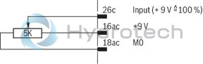
The command value voltage is either specified directly, by the regulated voltage +9 V of the power supply unit [6] or via an external command value potentiometer. For the "Command value 1" input, +9 V ≙ +100 % and for the "Command value 2" input, +6 V ≙ +100 %. The reference point for the command value inputs 1 and 2 is always M0 (18ac). Command value input 3 is a differential input [1] (0 to +10 V). It can be configured by setting jumpers as current input (0 to 20 mA or 4 to 20 mA). If the command value is specified by external electronics with a different reference potential, the differential input has to be used.
When disconnecting or connecting the command value voltage, it has to be ensured that both signal lines are in each case separated from or connected with the input. Before they are forwarded, all command values will be added up according to their absolute value and their sign [2]. Using the "Zw" potentiometer, offset voltages in the command value branch can be compensated.
External time potentiometer
External command value potentiometer (with 9 V command value input)
| For controlling proportional valves DBETR–1X |
| Communication: Command value input 0 ... 10 V |
| Electrical connection: 32-pin connector plug, form D for card holder or 19" racks |
| Component series 1X |
| Analog, euro-card format |
| For valves: DBETR, 2FRE |
| Data Sheet | Download Data Sheet |
| 3D CAD | Download 3D CAD |
| Manual | Download Manual |
| Manual | Download Manual |
| Manual | Download Manual |
| Manual | Download Manual |
| Manual | Download Manual |
| Manual | Download Manual |
| Manual | Download Manual |
| Manual | Download Manual |
| Manual | Download Manual |
| Manual | Download Manual |
| Electrical connection description | for card holder or 19" racks |
| Productgroup ID | 9,10,11,12,13,14 |
| Electrical connector | 32-pin connector plug, form D |
| Supply voltage | 24 VDC |
| Design | Printed circuit board |
| Weight | 0.20091 |
| Connectivity | Analog, command value 0 … 10 V |
|
01 |
Valve amplifier for proportional pressure valves with electrical position feedback, analog, euro-card format |
VT-VRPA1 |
|
02 |
For valves: DBETR-1X |
100 |
|
03 |
Component series 10 ... 19 (10 ... 19: unchanged installation and connection dimensions) |
1X |
|
04 |
Version: standard |
V0 |
|
05 |
Option: standard |
0 |
|
06 |
Further details in the plain text |
* |
|
01 |
02 |
03 |
04 |
05 |
06 |
|||||
|
VT-VRPA1 |
‒ |
100 |
‒ |
1X |
/ |
V0 |
/ |
0 |
/ |
* |
When replacing amplifier VT 5003, VT 5004 or VT 5010, the blind plate 4TE/3HE, material no. R900021004, must be ordered separately for the rack mounting.
Position transducer
|
Oscillator frequency |
f |
kHz |
2.5 ±10 % |
Supplementary information
|
Reference voltage 1) |
Potentiometer supply |
U |
V |
±9 (Imax = 25 mA) |
|
Anschlussart |
32-pole male multipoint connector, DIN EN 60603-2, design D | |||
|
Ambient temperature range |
ϑ |
°C |
0 … 50 | |
|
Storage temperature range |
ϑ |
°C |
-25 … 70 | |
|
Weight |
m |
kg |
0.15 | |
| 1) | With raised zero point |
Measuring sockets
|
Command value |
"w" |
Uw |
V |
0 ... 6 (Ri = 1 kΩ) |
|
Ramp time |
“down" |
Udown |
V |
0.02 ... 5 |
|
“up" |
Uup |
V |
0.02 ... -5 s | |
|
additional notices |
Ramp up, short: 0.02 V ≙ 5 s and 5 V ≙ 0.02 s, long: 0.02 V ≙ 50 s and 5 V ≙ 0,2 s Ramp down, short: -0.02 V ≙ 5 s and -5 V ≙ 0.02 s, long: -0.02 V ≙ 50 s and -5 V ≙ 0.2 s |
|||
|
Actual value 1) |
"x" |
Ux |
V |
0 ... -6 |
| 1) | Ri = 1 kΩ |
Anzeigen
|
LED display |
Green 1 |
Ready for operation | |
|
Yellow 1 |
Enable |
Adjustment options
|
Zero point calibration information |
-5 ... 30 % | |||
|
Amplitude attenuator |
for command value |
% |
0 ... 105 | |
|
Ramp time up/down |
Ramp 1 |
t |
s |
0.02 … 5 |
|
Ramp 2 |
t |
s |
0.2 … 50 | |
Solenoid outputs
|
Solenoid current |
max. |
Imax |
A |
2.2 |
|
Coil resistance at 20°C |
R(20) |
Ω |
10 | |
|
Clock frequency |
f |
Hz |
1.5 kHz | |
Analog inputs
|
Command value |
Voltage (differential input) |
U |
V |
0 ... 10 | |
|
Voltage 1) |
grounded on one side, first input |
Ucommand |
V |
0 … 9 | |
|
Voltage 1) |
grounded on one side, second input |
Ucommand |
V |
0 … 6 | |
|
Current |
I |
mA |
4 … 20 | ||
|
Current |
Input resistance |
R |
Ω |
100 | |
|
Alternative |
Current |
I |
mA |
0 … 20 | |
|
Current |
Input resistance |
R |
Ω |
100 | |
| 1) | Reference potential is M0 |
Voltage supply
|
Operating voltage |
nominal |
U |
V |
24 |
|
Lower limit value |
UB(t)min |
V |
22 | |
|
Upper limit value |
UB(t)max |
V |
35 | |
|
Power consumption |
max. |
Smax |
VA |
35 |
|
Current consumption |
max. |
Imax |
A |
1.5 |
|
Fuse |
2.5 A time-lag | |||
Digital inputs
|
Enable |
On (active) |
U |
V |
10 ... UB |
|
Off (inactive) |
U |
V |
0 ... 9 | |
|
Ramp on/off |
On (active) |
U |
V |
0 ... 9 |
|
Off (inactive) |
U |
V |
10 ... UB |
General
|
Component series |
1X | |
|
Type of electronics |
Analog | |
|
Design |
Euro-card |
For applications outside these parameters, please consult us!
Notice:
For information on environment simulation testing for the fields EMC (electro-magnetic compatibility), climate and mechanical load, see data sheet 30117-U
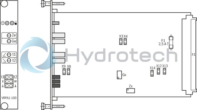
|
Function |
Jumper |
Factory setting |
||
|
Command value 3 |
X14 |
X12 |
X13 |
|
|
0 ... 10 V |

|
|
|
● |
|
0 ... 20 mA |
|

|
|
|
|
4 ... 20 mA |
|
|
|
|
Jumper
|
Function |
Jumper |
Factory setting |
|
|
Enable |
X3 |
||
|
on |
|
● |
|
|
Can be controlled externally |
|
||
|
Ramp |
X4 |
||
|
off |
|
● |
|
|
Can be controlled externally |
|
||
|
Ramp time |
X9 |
X8 |
|
|
0.02 ... 5 s |
|
|
● |
|
0.2 ... 50 s |
|
|
|
|
1) For use of amplifiers VT 5003, VT 5004 and VT 5010, jumper X3 (enable) has to be set to "on". |
|||
Potentiometer
|
Zero point command value |
|
|
Command value attenuator |
|
|
Ramp time "Ramp up" |
|
|
Ramp time "Ramp down" |
|
|
Zero point actual value |
|
|
Actual value attenuator |
Measuring sockets
|
Ramp time "Ramp up" |
|
|
Ramp time "Ramp down" |
|
|
Actual value |
|
|
Command value |
|
|
Reference potential |
LED displays

|
Ready for operation (green) |
|
|
Enable (yellow) |
|
1 |
Differential amplifier |
|
2 |
Summing device |
|
3 |
Ramp generator |
|
4 |
Threshold switch |
|
5 |
Enable circuit |
|
6 |
Power supply unit |
|
7 |
Command value limiter |
|
8 |
PID controller |
|
9 |
Fault recognition |
|
11 |
Summing device, controller |
|
12 |
Over-current identification |
|
13 |
Clocked output stage |
|
14 |
Oscillator |
|
15 |
Driver |
|
16 |
Demodulator |
|
17 |
Output stage |
|
18 |
Proportional valve |
|
19 |
Position transducer |
|
Zw |
Zero point command value |
|
Gw |
Command value attenuator |
|
Zx |
Zero point actual value |
|
Gx |
Actual value attenuator |
|
|
Ready for operation (green) |
|
|
Enable (yellow) |
|
t1 |
Ramp time "Ramp up" |
|
t2 |
Ramp time "Ramp down" |
|
X3...X14 |
See Operating and display elements |
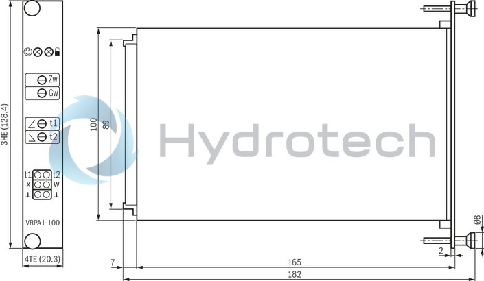
Dimensions in mm
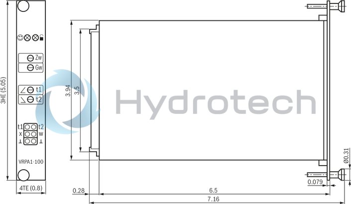
Dimensions in mm
The amplifier card must be configured according to its application. The amplifier card may only be unplugged and plugged when de-energized. No connectors with free-wheeling diodes or LED displays must be used for solenoid connection. Only carry out measurements at the card using instruments Ri > 100 kΩ. Measurement zero (M0) is increased by +9 V compared to 0 V operating voltage and not isolated, i.e. –9 V regulated voltage 0 V operating voltage. Thus, do not connect measurement zero (M0) to 0 V operating voltage. For switching command values, relays with gold-plated contacts have to be used (low voltages, low currents). Always shield command value lines; connect shielding to 0 V operating voltage on the card-side, other side open (risk of ground loops). Recommendation:
Also shield solenoid conductors.
For solenoid conductors up to a length of 50 m, use cable type LiYCY 1.5 mm2. For greater lengths, please contact us. The distance to aerial lines, radios, and radar systems has to be at least 1 m. Do not lay solenoid conductors and signal lines near power lines. Due to the charging power of the smoothing capacitor on the card, time-lag characteristics are required at the pre-fuses. Do not connect the port of the inductive position transducer marked with the ground sign with the ground. (Requirement for the compatibility with amplifier type VT 5003, VT 5004 and VT 5010) If the differential input is used, both inputs must always be connected or disconnected at the same time.