

BOSCH REXROTH
R900943087
$1,380.96 USD
- BOSCH REXROTH
- Material:R900943087
- Model:DZ20-2-5X/100Y/12
Quantity in stock: 0
The Bosch Rexroth DZ20-2-5X/100Y/12 (R900943087) is a sophisticated pilot-operated pressure sequence valve designed for the pressure-dependent connection of secondary systems. This valve is a critical component for managing hydraulic flow, ensuring that connections between channels are made once a set pressure threshold is reached. The main valve consists of a spool insert and a pilot control valve with various adjustment types and an optional check valve for enhanced functionality. The DZ20-2-5X/100Y/12 operates by utilizing the pressure in channel A to act on the pilot spool within the pilot control valve. When the pressure in channel P surpasses the preset value on the spring, it prompts movement against this spring, allowing hydraulic fluid to flow and causing a pressure drop at the main spool. This action opens up connections from channel A to B, with the differential set by another spring value. This particular model offers versatility through its configuration options such as preload, sequencing, and changeover functions. It is designed for subplate mounting with porting patterns conforming to ISO standards and can also be used as a cartridge valve. The different adjustment types available include a rotary knob, sleeve with hexagon and protective cap, lockable rotary knob with scale, or rotary knob with scale; providing flexibility according to user preference or system requirements. The optional check valve ensures free return flow if needed when there's higher pressure in the secondary circuit channel B than in channel A. The maximum operating pressure of this component series X reaches up to bar levels while it can handle maximum flow rates measured in liters per minute. In essence, this Bosch Rexroth sequence valve is suitable for applications requiring precise control over hydraulic system sequences and pressures within industrial settings where reliability and adaptability are paramount.
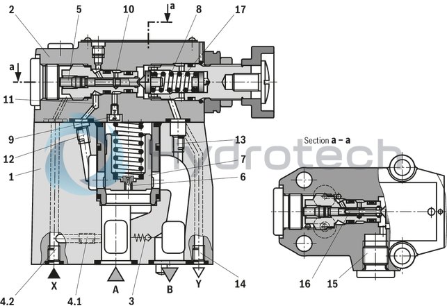
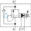
The valve type DZ is a pilot-operated pressure sequence valve.
It is applied for pressure-dependent connection of a second system.
The pressure sequence valve basically consists of main valve (1) with main spool insert (7) and pilot control valve (2) with adjustment type and optional check valve (3).
According to the pilot oil supply and return and the respective function, the following differentiation is made:
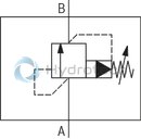
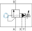
Preload valve type DZ. . -.-5X/… (control lines 4.1, 12 and 13 open; control lines 4.2, 14 and 15 closed)
The pressure applied in channel A acts via the control line (4.1) on the pilot spool (5) in the pilot control valve (2). Simultaneously, the pressure in channel A acts via the nozzle (6) on the spring-loaded side of the main spool (7). If the pressure in channel P exceeds the value set at the spring (8), the pilot spool (5) is moved against the spring (8). The hydraulic fluid on the spring-loaded side of the main spool (7) now flows via the nozzle (9), the control edge (10) and control lines (11) and (12) into channel B. Due to this, a pressure drop occurs at the main spool (7). The main spool (7) is moved upwards and opens the connections from channel A to B. The pressure in channel A exceeds the value in channel B by the value set at the spring (8). The leakage occurring at the pilot spool (5) is directed internally via the spring chamber (17) of the pilot control valve and the control line (13) into channel B. If the pressure in the secondary circuit (channel B) exceeds the pressure in channel A, a check valve (3) may be optionally installed for free return flow.
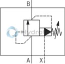
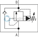
Preload valve type DZ. . -.-5X/.X… (control lines 4.2, 12 and 13 open; control lines 4.1, 14 and 15 closed)
In principle, the function of this valve corresponds to the function of type DZ. . -.-5X/…. With version "X", however, the opening signal is received externally via control line X (4.2).
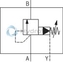
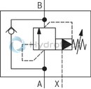
Sequence valve type DZ. . -.-5X/.Y… (control lines 4.1, 12 and 14 or 15 open; control lines 4.2 and 13 closed)
In principle, the function of this valve corresponds to the function of type DZ. . -.-5X/…. At version "Y", however, the leakage occurring at the pilot spool (5) has to be directed via line (14) or (15) to the tank by means of a depressurized connection. The pilot oil is directed via line (11) and (12) into channel B.
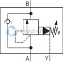
Circulation valve type DZ. . -.-5X/.XY… (control lines 4.2, 14 or 15 open; control lines 4.1, 12 and 13 closed)
In principle, the function of this valve corresponds to the function of type DZ. . -.-5X/…. With version "XY", however, the opening signal is received externally via control line X (4.2). The pilot oil at the pilot spool (16) bore and occurring leakage have to be directed via line (14) or (15) to the tank by means of a depressurized connection.
|
01 |
02 |
03 |
04 |
05 |
06 |
07 |
08 |
09 |
10 |
|||
|
DZ |
– |
– |
5X |
/ |
* |
|
01 |
Pressure sequence valve, pilot-operated |
DZ |
|
02 |
Valve complete (subplate mounting) |
no code |
|
Pilot control valve without main spool insert (cartridge valve) (do not enter nominal size) |
C |
|
|
Pilot control valve with main spool insert (cartridge valve) (enter valve size 30) |
C |
|
|
03 |
Size 10 |
10 |
|
Size 25 |
20 |
|
|
Size 32 |
30 |
|
|
Adjustment type |
||
|
04 |
Rotary knob |
1 |
|
Sleeve with hexagon and protective cap |
2 |
|
|
Lockable rotary knob with scale |
3 1) |
|
|
Rotary knob with scale |
7 |
|
|
05 |
Component series 50 … 59 (50 … 59: unchanged installation and connection dimensions) |
5X |
|
Set pressure |
||
|
06 |
50 bar |
50 |
|
100 bar |
100 |
|
|
200 bar |
200 |
|
|
315 bar |
315 |
|
|
Pilot oil supply |
||
|
07 |
Pilot oil supply internal, pilot oil return internal |
no code |
|
External pilot oil supply, internal pilot oil return 2) |
X |
|
|
Internal pilot oil supply, external pilot oil return 2) |
Y |
|
|
External pilot oil supply, external pilot oil return (see symbols) |
XY |
|
|
08 |
With check valve 2) |
no code |
|
Without check valve |
M |
|
|
Seal material |
||
|
09 |
NBR seals |
no code |
|
FKM seals (other seals upon request) |
V |
|
|
Observe compatibility of seals with hydraulic fluid used. |
||
|
10 |
Further details in the plain text |
* |
| 1) H-key with material no. R900008158 is included in the scope of delivery. | |
| 2) Not with version "C" |
Preferred types and standard units are specified in the EPS (standard price list).
hydraulic
|
Size |
10 | 25 | 32 | ||
|
Maximum operating pressure |
Anschluss A |
bar |
315 | ||
|
Port B |
bar |
315 | |||
|
Port X |
bar |
315 | |||
|
Maximum counter pressure |
Port Y |
bar |
315 | ||
|
Minimum set pressure |
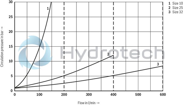
flow-dependent, see characteristic curves | ||||
|
Maximum set pressure |
bar |
50 100 200 315 |
|||
|
Maximum flow |
l/min |
200 | 400 | 600 | |
|
Hydraulic fluid |
see table | ||||
|
Hydraulic fluid temperature range |
NBR seals |
°C |
-30 … +80 | ||
|
FKM seals |
°C |
-20 … +80 | |||
|
Viscosity range |
mm²/s |
10 … 800 | |||
|
Maximum admissible degree of contamination of the hydraulic fluid 1) |
Class 20/18/15 according to ISO 4406 (c) | ||||
| 1) | The cleanliness classes specified for the components must be adhered to in hydraulic systems. Effective filtration prevents faults and simultaneously increases the life cycle of the components. For the selection of the filters, see www.boschrexroth.com/filter. |
|
Hydraulic fluid |
Classification |
Suitable sealing materials |
Standards |
|
|
Mineral oils and related hydrocarbons |
HL, HLP, HLPD |
NBR, FKM |
DIN 51524 |
|
|
Environmentally compatible |
Insoluble in water |
HETG |
NBR, FKM |
ISO 15380 |
|
HEES |
FKM |
|||
|
Soluble in water |
HEPG |
FKM |
ISO 15380 |
|
|
Containing water |
Water-free |
HFDU, HFDR |
FKM |
ISO 12922 |
|
Containing water |
HFC (Fuchs Hydrotherm 46M, Petrofer Ultra Safe 620) |
NBR |
ISO 12922 |
|
|
Important information on hydraulic fluids! For further information and data on the use of other hydraulic fluids, please refer to data sheet 90220 or contact us! There may be limitations regarding the technical valve data (temperature, pressure range, life cycle, maintenance intervals, etc.)!Flame-resistant – containing water: Maximum operating pressure 210 bar Maximum hydraulic fluid temperature 60 °C Expected life cycle as compared to HLP hydraulic oil 30 % to 100 % |
||||
general
|
Size |
10 | 25 | 32 | ||
|
Weight |
Type DZ ... |
kg |
3.4 | 5.3 | 8 |
|
Type DZC ... |
kg |
1.2 | |||
|
Type DZC 30 ... |
kg |
1.5 | |||
|
Installation position |
any | ||||
|
Ambient temperature range |
NBR seals |
°C |
-30 … +80 | ||
|
FKM seals |
°C |
-20 … +80 | |||
For applications outside these parameters, please consult us!
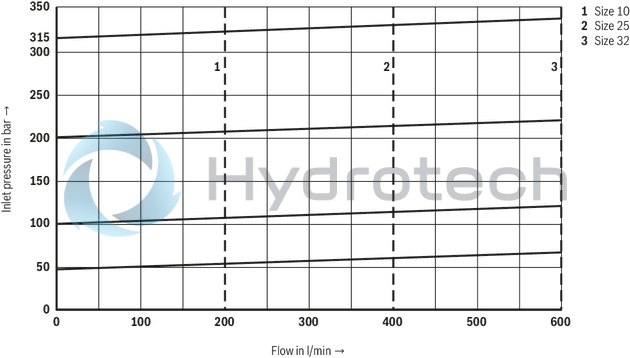
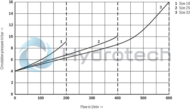
(measured with HLP46, ϑOil = 40 ±5 °C)
Inlet pressure dependent on the flow (A → B)
Minimum inlet pressure 1) dependent on the flow (A → B)
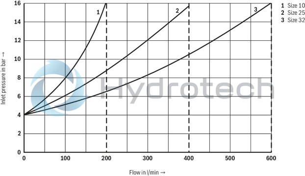
| 1) Circulation pressure with version "X" |
The characteristic curves apply to the pressure at the valve outlet pT = 0 bar across the entire flow range.
Circulation pressure dependent on the flow (A → B) (only version "XY")
Δp-qV characteristic curves via check valve (B → A)
Type DZ. . -.-5X/.M…
Type DZ. . -.-5X/.XM…
Type DZ. . -.-5X/.YM…
Type DZ. . -.-5X/.XYM…
Type DZ. . -.-5X/…
Type DZ. . -.-5X/.X…
Type DZ. . -.-5X/.Y…
Type DZ. . -.-5X/.XY…
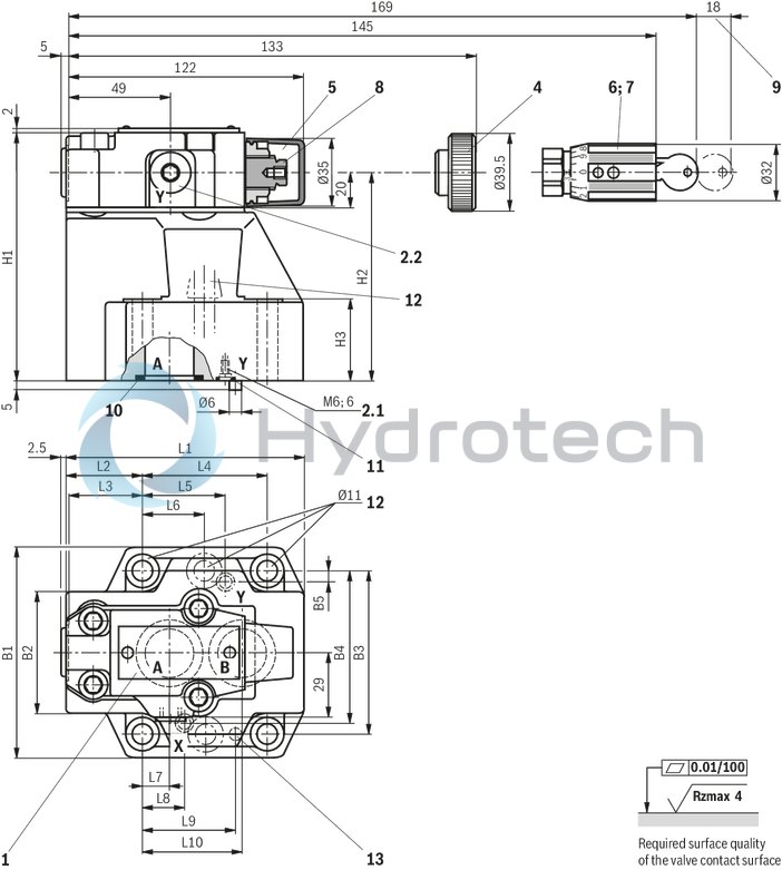
Subplate mounting
Dimensions in mm
|
1 |
Name plate |
|
2.1 |
Port Y for external pilot oil return at version "XY" or spring chamber discharge at version "Y" |
|
2.2 |
Port Y (G1/4) optionally for external pilot oil return at version "XY" or spring chamber discharge at version "Y" |
|
4 |
Adjustment type "1" |
|
5 |
Adjustment type "2" |
|
6 |
Adjustment type "3" |
|
7 |
Adjustment type "7" |
|
8 |
Hexagon SW10 |
|
9 |
Space required to remove the key |
|
10 |
Identical seal rings for ports A and B |
|
11 |
Identical seal rings for ports X, Y, Y1 and Y2 |
|
12 |
Valve mounting bores |
|
13 |
Locking pin |
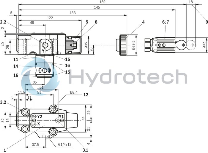
Cartridge valve
Dimensions in mm
|
1 |
Name plate |
|
2.2 |
Port Y (G1/4) optionally for external pilot oil return at version "XY" or spring chamber discharge at version "Y" |
|
3.1 |
Port Y1 at cartridge valve for pilot oil return at version "XY" or spring chamber discharge at version "no code", "X" and "Y" |
|
3.2 |
Port Y2 at cartridge valve for pilot oil return at version "no code", "X" and "Y" |
|
4 |
Adjustment type "1" |
|
5 |
Adjustment type "2" |
|
6 |
Adjustment type "3" |
|
7 |
Adjustment type "7" |
|
8 |
Hexagon SW10 |
|
9 |
Space required to remove the key |
|
11 |
Identical seal rings for ports X, Y, Y1 and Y2 |
|
12 |
Valve mounting bores |
|
14 |
Main spool insert with nozzle |
|
15 |
Seal ring (main spool) |
|
16 |
Support ring (main spool) |
Installation bore
Dimensions in mm
Dimensions in mm
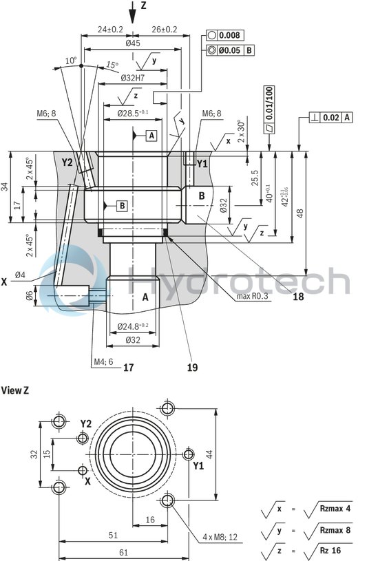
|
17 |
Versions "X" and "XY" without bore |
|
18 |
Notice! |
|
19 |
Support ring and seal ring are to be inserted into this bore before assembly of the main spool. |
Subplates (separate order)
NG10G 460/01 (G3/8)
G 461/01 (G1/2)
NG25G 412/01 (G3/4)
G 413/01 (G1)
NG32G 414/01 (G1 1/4)
G 415/01 (G1 1/2)
Valve mounting screws (separate order)
For reasons of stability, exclusively the following valve mounting screws may be used:
Subplate mounting:
NG104 x ISO 4762 - M10 x 50 - 10.9-flZn-240h-L
at friction coefficient μtotal = 0.09 to 0.14,
Tightening torque MA = 60 Nm ±10 %,
material no. R913000471
NG254 x ISO 4762 - M10 x 60 - 10.9-flZn-240h-L
at friction coefficient μtotal = 0.09 to 0.14,
Tightening torque MA = 60 Nm ±10 %,
material no. R913000116
NG326 x ISO 4762 - M10 x 70 - 10.9-flZn-240h-L
at friction coefficient μtotal = 0.09 to 0.14,
Tightening torque MA = 60 Nm ±10 %,
material no. R913000126
Cartridge valve:
4 x ISO 4762 - M8 x 40 - 10.9-flZn-240h-L
at friction coefficient μtotal = 0.09 to 0.14,
Tightening torque MA = 31 Nm ±10 %,
material no. R913000205
The tightening torques are guidelines when using screws with the specified friction coefficients and when using a manual torque wrench (tolerance ±10 %).
|
NG |
L1 |
L2 |
L3 |
L4 |
L5 |
L6 |
L7 |
L8 |
L9 |
L10 |
B1 |
B2 |
B3 |
B4 |
B5 |
H1 |
H2 |
H3 |
|
mm |
mm |
mm |
mm |
mm |
mm |
mm |
mm |
mm |
mm |
mm |
mm |
mm |
mm |
mm |
mm |
mm |
mm |
|
| 10 | 96 | 35.5 | 33 | 42.9 | 21.5 | - | 7.2 | 21.5 | 31.8 | 35.8 | 85 | 50 | 66.7 | 58.8 | 7.9 | 112 | 92 | 28 |
| 25 | 116 | 37.5 | 35.4 | 60.3 | 39.7 | - | 11.1 | 20.6 | 44.5 | 49.2 | 102 | 59.5 | 79.4 | 73 | 6.4 | 122 | 102 | 38 |
| 32 | 145 | 33 | 29.8 | 84.2 | 59.5 | 42.1 | 16.7 | 24.6 | 62.7 | 67.5 | 120 | 76 | 96.8 | 92.8 | 3.8 | 130 | 110 | 46 |