
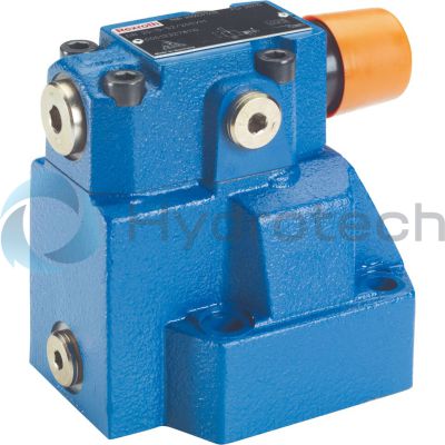
BOSCH REXROTH
R900596766
$1,289.23 USD
- BOSCH REXROTH
- Material:R900596766
- Model:DR10-5-5X/100Y
Quantity in stock: 0
The Bosch Rexroth DR10-5-5X/100Y (R900596766) is a high-performance industrial hydraulic valve designed for reliable pressure reduction to a predetermined setting value. This mechanically actuated valve is part of Bosch Rexroth's product group and showcases a spool symbol of B A, indicating its flow path. It operates with a maximum pressure capacity and features multiple ports for versatile connectivity. The type of actuation is mechanical, ensuring robust and direct control. With a size designation of B, the DR10-5-5X/100Y can handle a substantial max flow rate, making it suitable for various hydraulic applications. It employs subplate mounting for secure installation and conforms to ISO connection diagrams, which facilitates its integration into standardized systems. The valve has multiple switching positions and comes with NBR seals that are compatible with hydraulic fluids such as HL, HLP, HLPD, HVLP, HVLPD, and HFC. Pressure valves like the DR10-5-5X/100Y function by allowing fluid to flow from channel B to channel A unrestrictedly in their rest position. When the pressure in channel A exceeds the spring-set value, the control spool begins to close off the flow. The balance between the pressure in channel A and the spring setting determines the reduced pressure level achieved by this valve. An external pilot oil return ensures proper functioning while an optional check valve can be installed for free return flow from channel A to B. Additionally, users can monitor pressure adjustments via a pressure gauge connection that controls reduced pressure in channel A. Available adjustment types for this model include options such as rotary knob, sleeve with hexagon and protective cap, lockable rotary knob with scale, or rotary knob with scale—offering flexibility according to user preferences. The DR10-5-5X/100Y also supports various pressure ratings and can include an optional check valve when subplate mounted. It is part of component series X which specifies its modern design attributes and confirms its capability to withstand maximum operating pressures up to specified bar levels while maintaining maximum flow rates expressed in liters per minute (l/min).
Size 10, B → A, mechanically actuated
Industrial hydraulic valve in a high performance range. Reliable pressure reduction to setting value.
Unpacked Weight: 3.660 kg
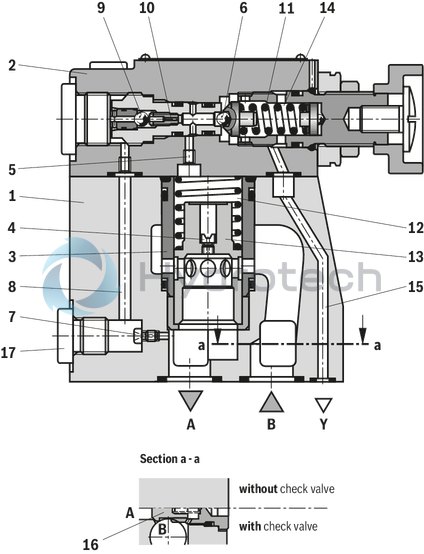
Pressure valves type DR are pilot-operated pressure reducing valves controlled from the secondary circuit.
The pressure reducing valves basically consist of the main valve (1) with main spool insert (3) and pilot control valve (2) with pressure adjustment element.
Basic principle:
In rest position, the valves are open. Hydraulic fluid can flow via the main spool insert (3) from channel B to channel A without restrictions. The pressure applied in channel A acts on the bottom of the main spool. Simultaneously, pressure is applied via the nozzle (4) to the spring-loaded side of the main spool (3) and via channel (5) to ball (6) in the pilot control valve (2). Similarly, it acts via nozzle (7), control line (8), check valve (9) and nozzle (10) on the ball (6). Depending on the setting of the spring (11), pressure builds up upstream of the ball (6), in channel (5) and in the spring chamber (12) holding the control spool (13) in open position. The hydraulic fluid in channel B can flow via the main spool insert (3) to channel A without restrictions until a pressure builds up in channel A exceeding the value set at the spring (11) and opening the ball (6). The control spool (13) is moved into closing direction.
The desired reduced pressure is reached if there is a balance between the pressure in channel A and the pressure set at the spring (11).
The pilot oil return from the spring chamber (14) is always realized externally via the control line (15) into the tank.
For the free return flow from channel A to channel B, a check valve (16) can optionally be installed.
A pressure gauge connection (17) enables control of the reduced pressure in channel A.
Type DR..-4-5X/...Y...
| Size 10 … 32 |
| Component series 5X |
| Maximum operating pressure 350 bar |
| Maximum flow 400 l/min |
| Data Sheet | Download Data Sheet |
| Manual | Download Manual |
| Manual | Download Manual |
| Manual | Download Manual |
| Manual | Download Manual |
| Manual | Download Manual |
| Spool symbol | B → A |
| Max. pressure | 350 |
| Productgroup ID | 9,10,11,12,13,14 |
| Number of ports | 2 |
| Type of actuation | with mechanical actuation |
| Size | 10 |
| Max. flow | 150 |
| Type of connection | Subplate mounting |
| Connection diagram | ISO 5781-06-07-0-16 |
| Number of switching positions | 2 |
| Weight | 3.660 |
| Seals | NBR |
| Hydraulic fluid | HL,HLP,HLPD,HVLP,HVLPD,HFC |
|
01 |
02 |
03 |
04 |
05 |
06 |
07 |
08 |
09 |
10 |
11 |
||
|
DR |
– |
5X |
/ |
Y |
* |
|
01 |
3-way pressure reducing valve |
DR |
|
|
02 |
Valve complete (subplate mounting or threaded connection) |
no code |
|
|
Pilot control valve without main spool insert (cartridge valve) (do not enter nominal size) |
C |
||
|
Pilot control valve with main spool insert (cartridge valve) (enter valve size 30) |
C |
||
|
03 |
Size |
Ordering code |
|
|
Subplate mounting "–" |
Threaded connection "G" |
||
|
10 |
= 10 |
= 10 (G1/2) |
|
|
16 |
– |
= 15 (G3/4) |
|
|
25 |
= 20 |
= 20 (G1) |
|
|
25 |
– |
= 25 (G1 1/4) |
|
|
32 |
= 30 |
= 30 (G1 1/2) |
|
|
04 |
As cartridge valve (version "C", without main spool insert) |
no code |
|
|
As cartridge valve (version "C", with main spool insert) |
– |
||
|
For subplate mounting |
– |
||
|
For threaded connection |
G |
||
|
Adjustment type for pressure adjustment |
|||
|
05 |
Rotary knob |
4 |
|
|
Sleeve with hexagon and protective cap (always at maximum pressure adjustment) |
5 |
||
|
Lockable rotary knob with scale |
6 1) |
||
|
Rotary knob with scale |
7 |
||
|
06 |
Component series 50 … 59 (50 … 59: unchanged installation and connection dimensions) |
5X |
|
|
07 |
Set pressure up to 50 bar |
50 |
|
|
Set pressure up to 100 bar |
100 |
||
|
Set pressure up to 200 bar |
200 |
||
|
Set pressure up to 315 bar |
315 |
||
|
Set pressure up to 350 bar (only version "M") |
350 |
||
|
Pilot oil supply |
|||
|
08 |
Internal pilot oil supply, external pilot oil return |
Y |
|
|
09 |
With check valve (only for subplate mounting) |
no code |
|
|
Without check valve |
M |
||
|
Seal material |
|||
|
10 |
NBR seals |
no code |
|
|
FKM seals (other seals upon request) |
V |
||
|
Observe compatibility of seals with hydraulic fluid used. |
|||
|
11 |
Further details in the plain text |
* |
|
| 1) H-key with material no. R900008158 is included in the scope of delivery. |
general
|
Size |
10 | 16 | 25 | 25 | 32 | |||
|
Type |
10 | 16 (Typ DR...15) | 25 (Typ DR..20) | 25 (Typ DR...25) | 32 (Typ DR...30) | |||
|
Weight |
Subplate mounting |
Type DR . .‒ |
kg |
3.4 | - | 5.3 | - | 8 |
|
Cartridge valve |
Type DRC |
kg |
1.2 | |||||
|
Type DRC 30 |
kg |
1.5 | ||||||
|
Threaded connection |
Type DR . .G |
kg |
5.3 | 5.2 | 5.1 | 5 | 4.8 | |
|
Installation position |
any | |||||||
|
Ambient temperature range |
NBR seals |
°C |
-30 … +50 | |||||
|
FKM seals |
°C |
-20 … +50 | ||||||
hydraulic
|
Size |
10 | 16 | 25 | 32 | |||
|
Maximum operating pressure 1) |
Port B |
bar |
350 | ||||
|
Maximum inlet pressure 1) |
Port B |
bar |
350 | ||||
|
Maximum outlet pressure 1) |
Port … |
bar |
350 | ||||
|
Operating pressure range 1) |
Anschluss A |
bar |
10 … 350 | ||||
|
Maximum counter pressure 1) |
Port Y |
bar |
350 | ||||
|
Minimum set pressure |
flow-dependent, see characteristic curves | ||||||
|
Maximum set pressure 1) |
bar |
50 100 200 315 350 |
|||||
|
Maximum flow |
Subplate mounting |
l/min |
150 | - | 300 | - | 400 |
|
Threaded connection |
l/min |
150 | 300 | 400 | |||
|
Hydraulic fluid |
see table | ||||||
|
Hydraulic fluid temperature range |
NBR seals |
°C |
-30 … +80 | ||||
|
FKM seals |
°C |
-20 … +80 | |||||
|
Viscosity range |
mm²/s |
10 … 800 | |||||
|
Maximum admissible degree of contamination of the hydraulic fluid 2) |
Class 20/18/15 according to ISO 4406 (c) | ||||||
| 1) | 350 bar only possible at version without check valve |
| 2) | The cleanliness classes specified for the components must be adhered to in hydraulic systems. Effective filtration prevents faults and simultaneously increases the life cycle of the components. For the selection of the filters, see www.boschrexroth.com/filter. |
|
Hydraulic fluid |
Classification |
Suitable sealing materials |
Standards |
|
|
Mineral oils and related hydrocarbons |
HL, HLP, HLPD |
NBR, FKM |
DIN 51524 |
|
|
Environmentally compatible |
Insoluble in water |
HETG |
NBR, FKM |
ISO 15380 |
|
HEES |
FKM |
|||
|
Soluble in water |
HEPG |
FKM |
ISO 15380 |
|
|
Containing water |
Water-free |
HFDU, HFDR |
FKM |
ISO 12922 |
|
Containing water |
HFC (Fuchs Hydrotherm 46M, Petrofer Ultra Safe 620) |
NBR |
ISO 12922 |
|
|
Important information on hydraulic fluids! For further information and data on the use of other hydraulic fluids, please refer to data sheet 90220 or contact us! There may be limitations regarding the technical valve data (temperature, pressure range, life cycle, maintenance intervals, etc.)!Flame-resistant – containing water: Maximum operating pressure 210 bar Maximum hydraulic fluid temperature 60 °C Expected life cycle as compared to HLP hydraulic oil 30 % to 100 % |
||||
For applications outside these parameters, please consult us!
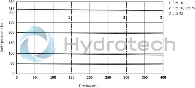
(measured with HLP46, ϑOil = 40 ±5 °C)
Outlet pressure pA dependent on the flow qV (B to A)
Minimum set pressure pAmin dependent on the flow qV (B to A)
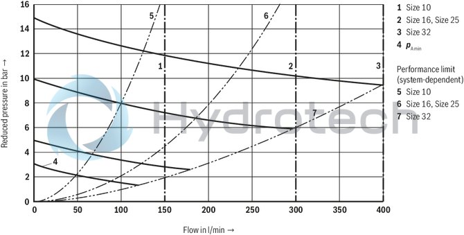
The characteristic curves apply to the pressure at the valve outlet pT = 0 bar across the entire flow range.
Δp-qV characteristic curve (B to A; minimum adjustable pressure differential)
Pilot flow dependent on flow (B to A) and pressure differential
Δp-qV characteristic curves via check valve (A to B)
Type DR…YM

Type DR…Y
Type DRC…; cartridge valve
Dimensions in mm
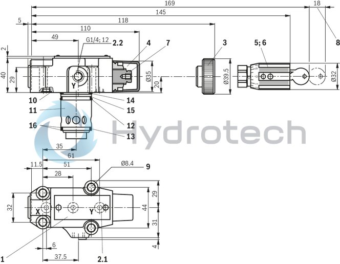
|
1 |
Name plate |
|
2.1 |
Y port for pilot oil return, external |
|
2.2 |
Port Y optionally for external pilot oil return |
|
3 |
Adjustment type "4" |
|
4 |
Adjustment type "5" |
|
5 |
Adjustment type "6" |
|
6 |
Adjustment type "7" |
|
7 |
Hexagon SW10 |
|
8 |
Space required to remove the key |
|
9 |
Valve mounting bores |
|
10 |
Seal rings |
|
11 |
Main spool insert |
|
12 |
Seal ring |
|
13 |
Seal ring |
|
14 |
Seal ring |
|
15 |
Support ring |
|
16 |
Support ring |
Valve mounting screws (separate order)
4 hexagon socket head cap screws, metric
ISO 4762 - M8 x 40 - 10.9-flZn-240h-L
at friction coefficient μtotal = 0.09 to 0.14,
Tightening torque MA = 31 Nm ± 10 %,
material no. R913000205
Type DR…; threaded connection
Dimensions in mm
|
1 |
Name plate |
|
2.1 |
Y port for pilot oil return, external |
|
3 |
Adjustment type "4" |
|
4 |
Adjustment type "5" |
|
5 |
Adjustment type "6" |
|
6 |
Adjustment type "7" |
|
7 |
Hexagon SW10 |
|
8 |
Space required to remove the key |
|
9 |
Valve mounting bores |
|
17 |
Pressure gauge connection |
|
NG |
D1 |
ØD2 |
T1 |
|
mm |
mm |
||
| 10 | G1/2 | 34 | 14 |
| 16 (Typ DR...15) | G3/4 | 42 | 16 |
| 25 (Typ DR..20) | G1 | 47 | 18 |
| 25 (Typ DR...25) | G1 1/4 | 58 | 20 |
| 32 (Typ DR...30) | G1 1/2 | 65 | 22 |
Type DR…; subplate mounting
Dimensions in mm
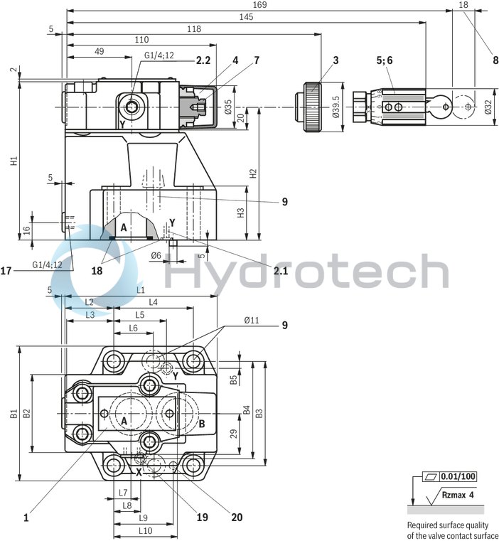
|
1 |
Name plate |
|
2.1 |
Y port for pilot oil return, external |
|
2.2 |
Port Y optionally for external pilot oil return |
|
3 |
Adjustment type "4" |
|
4 |
Adjustment type "5" |
|
5 |
Adjustment type "6" |
|
6 |
Adjustment type "7" |
|
7 |
Hexagon SW10 |
|
8 |
Space required to remove the key |
|
9 |
Valve mounting bores |
|
17 |
Pressure gauge connection |
|
18 |
Identical seal rings for ports A and B |
|
Identical seal rings for ports X and Y |
|
|
19 |
Port X without function (blind bore) |
|
20 |
Locking pin |
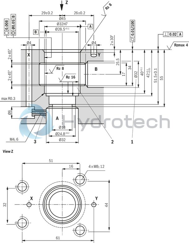
Subplate mounting:
Subplates (separate order)
Size 10G 460/01 (G3/8)
G 461/01 (G1/2)
Size 20G 412/01 (G3/4)
G 413/01 (G1)
Size 30G 414/01 (G1 1/4)
G 415/01 (G1 1/2)
|
1 |
Notice! Bore Ø32 can cut into Ø45 at any position. However, it must be observed that the connection bores and valve mounting bore are not damaged! |
|
2 |
Support ring and seal rings are to be inserted into this bore before assembly of the main spool! |
|
3 |
Nozzle, separate order |
Valve mounting screws (separate order)
Size 104 hexagon socket head cap screws, metric
ISO 4762 - M10 x 50 - 10.9-flZn-240h-L
at friction coefficient μtotal = 0.09 to 0.14,
Tightening torque MA = 60 Nm ± 10 %,
material no. R913000471
Size 204 x ISO 4762 - M10 x 60 - 10.9-flZn-240h-L
at friction coefficient μtotal = 0.09 to 0.14,
Tightening torque MA = 60 Nm ± 10 %,
material no. R913000116
Size 306 x ISO 4762 - M10 x 70 - 10.9-flZn-240h-L
at friction coefficient μtotal = 0.09 to 0.14,
Tightening torque MA = 60 Nm ± 10 %,
material no. R913000126
|
NG |
L1 |
L2 |
L3 |
L4 |
L5 |
L6 |
L7 |
L8 |
L9 |
L10 |
B1 |
B2 |
B3 |
B4 |
B5 |
H1 |
H2 |
H3 |
|
mm |
mm |
mm |
mm |
mm |
mm |
mm |
mm |
mm |
mm |
mm |
mm |
mm |
mm |
mm |
mm |
mm |
mm |
|
| 10 | 96 | 35.5 | 33 | 42.9 | 21.5 | - | 7.2 | 21.5 | 31.8 | 35.8 | 85 | 50 | 66.7 | 58.8 | 7.9 | 112 | 92 | 28 |
| 16 | - | - | - | - | - | - | - | - | - | - | - | - | - | - | - | - | - | - |
| 25 | 116 | 37.5 | 35.4 | 60.3 | 39.7 | - | 11.1 | 20.6 | 44.5 | 49.2 | 102 | 59.5 | 79.4 | 73 | 6.4 | 122 | 102 | 38 |
| 25 | - | - | - | - | - | - | - | - | - | - | - | - | - | - | - | - | - | - |
| 32 | 145 | 33 | 29.8 | 84.2 | 59.5 | 42.1 | 16.7 | 24.6 | 62.7 | 67.5 | 120 | 76 | 96.8 | 92.8 | 3.8 | 130 | 110 | 46 |
Valve mounting screws (separate order)
4 hexagon socket head cap screws, metric
ISO 4762 - M8 x 40 - 10.9-flZn-240h-L
at friction coefficient μtotal = 0.09 to 0.14,
Tightening torque MA = 31 Nm ± 10 %,
material no. R913000205
Installation bore
Dimensions in mm
Dimensions in mm
|
1 |
Notice! Bore Ø32 can cut into Ø45 at any position. However, it must be observed that the connection bores and valve mounting bore are not damaged! |
|
2 |
Support ring and seal rings are to be inserted into this bore before assembly of the main spool! |
|
3 |
Nozzle, separate order |
Valve mounting screws (separate order)
Size 104 hexagon socket head cap screws, metric
ISO 4762 - M10 x 50 - 10.9-flZn-240h-L
at friction coefficient μtotal = 0.09 to 0.14,
Tightening torque MA = 60 Nm ± 10 %,
material no. R913000471
Size 204 x ISO 4762 - M10 x 60 - 10.9-flZn-240h-L
at friction coefficient μtotal = 0.09 to 0.14,
Tightening torque MA = 60 Nm ± 10 %,
material no. R913000116
Size 306 x ISO 4762 - M10 x 70 - 10.9-flZn-240h-L
at friction coefficient μtotal = 0.09 to 0.14,
Tightening torque MA = 60 Nm ± 10 %,
material no. R913000126