BOSCH REXROTH
R900459500
$4,008.82 USD
- BOSCH REXROTH
- Material:R900459500
- Model:F10P3-3X/16Q
Quantity in stock: 0
The Bosch Rexroth F10P3-3X/16Q (R900459500) is a state-of-the-art flow control valve designed for precise throttling of fluid flow with minimal temperature dependency. This fine throttle valve features a robust housing, an adjustable element, and an orifice that together ensure reliable performance in regulating flow rates. The component is engineered for versatility with options for subplate mounting, threaded connections, or block installation, catering to a wide range of system configurations. With its lockable rotary knob, the F10P3-3X/16Q allows for secure settings to maintain consistent flow rates even in demanding applications. The valve's design incorporates an orifice window where the flow from port A to B is meticulously throttled by rotating the curved bolt, allowing for fine-tuned control over the hydraulic system's performance. The precision of this mechanism ensures that adjustments can be made smoothly and with high accuracy. This model belongs to component series X and can withstand a maximum operating pressure of up to 315 bar while handling maximum flow rates as specified by the manufacturer. The F10P3-3X/16Q's durable construction and reliable operation make it an essential component for systems requiring precise fluid control with stable characteristics across varying temperatures. It is particularly suitable for applications where exact flow regulation is critical to the system’s operation and efficiency.
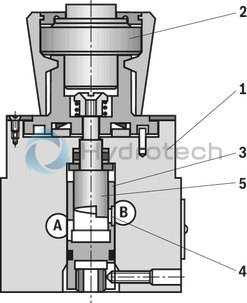
The flow control valve type F is a fine throttle valve with an orifice-type throttling point. It basically consists of housing (1), adjustment element (2) and orifice (3) and is used for throttling of a flow with low temperature dependency.
The flow from A to B is throttled at the orifice window (4). The throttle cross-section is set by rotation of the curved bolt (5). Low temperature dependency is achieved thanks to the orifice design of the throttling point.
|
01 |
02 |
03 |
04 |
05 |
06 |
07 |
08 |
||
|
F |
3 |
– |
/ |
* |
|
01 |
Fine throttle |
F |
||||
|
02 |
Size 5 |
5 |
||||
|
Size 10 |
10 |
|||||
|
03 |
for block installation |
K |
||||
|
For threaded connection |
G |
|||||
|
For subplate mounting |
P |
|||||
|
04 |
3 |
|||||
|
05 |
Component series 20 ... 29 (version "K") (20 ... 29: unchanged installation and connection dimensions) |
2X |
||||
|
Component series 30 ... 39 (version “G and “P”) (30 ... 39: unchanged installation and connection dimensions) |
3X |
|||||
|
06 |
NG25 |
Size 10 |
||||
|
progressive |
progressive |
Linear |
||||
|
Orifice 0.2 |
0,2Q |
Orifice 5 |
5Q |
Orifice 2 |
2L |
|
|
Orifice 0.6 |
0,6Q |
Orifice 10 |
10Q |
Orifice 5 |
5L |
|
|
Orifice 1.2 |
1,2Q |
Orifice 16 |
16Q |
Orifice 10 |
10L |
|
|
Orifice 3 |
3Q |
Orifice 25 |
25Q |
Orifice 16 |
16L |
|
|
Orifice 6 |
6Q |
Orifice 25 |
25L |
|||
|
Orifice 10 |
10Q |
Orifice 50 |
50L |
|||
|
Seal material |
||||||
|
07 |
NBR seals |
no code |
||||
|
FKM seals |
V |
|||||
|
Observe compatibility of seals with hydraulic fluid used. |
||||||
|
08 |
Further details in the plain text |
* |
||||
general
|
Size |
5 | 10 | ||
|
Weight |
Block installation |
kg |
1 | |
|
Threaded connection |
kg |
1.6 | ||
|
Subplate mounting |
kg |
1.4 | ||
|
Installation position |
any | |||
|
Ambient temperature range |
NBR seals |
°C |
-30 … +80 | |
|
FKM seals |
°C |
-20 … +80 | ||
hydraulic
|
Size |
5 | 10 | ||
|
Maximum operating pressure |
bar |
210 | ||
|
Maximum flow |
l/min |
80 | ||
|
Hydraulic fluid |
see table | |||
|
Hydraulic fluid temperature range |
NBR seals |
°C |
-30 … +80 | |
|
FKM seals |
°C |
-20 … +80 | ||
|
Viscosity range |
mm²/s |
2.8 … 380 | ||
|
Maximum admissible degree of contamination of the hydraulic fluid 1) |
Class 20/18/15 according to ISO 4406 (c) | |||
|
Adjustment angle |
° |
300 | ||
|
Actuating torque |
at 100 bar |
Nm |
1.1 | |
|
at 200 bar |
Nm |
1.8 | ||
| 1) | The cleanliness classes specified for the components must be adhered to in hydraulic systems. Effective filtration prevents faults and simultaneously increases the life cycle of the components. For the selection of the filters, see www.boschrexroth.com/filter. |
|
Hydraulic fluid |
Classification |
Suitable sealing materials |
Standards |
|
|
Mineral oil |
HL, HLP |
FKM, NBR |
DIN 51524 |
|
|
Bio-degradable |
Insoluble in water |
HEES (synthetic esters) |
FKM |
VDMA 24568 |
|
HETG (rape seed oil) |
FKM, NBR |
|||
|
Soluble in water |
HEPG (polyglycols) |
FKM |
VDMA 24568 |
|
|
Other hydraulic fluids on request |
||||
For applications outside these parameters, please consult us!
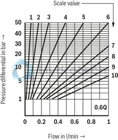
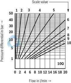
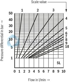
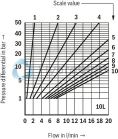
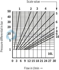
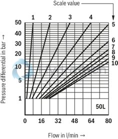
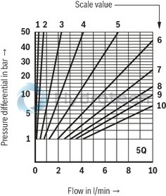
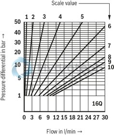
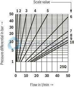
(measured with HLP46, ϑOil = 40 ±5 °C)
Δp-qV characteristic curves: NG5
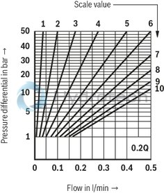
Δp-qV characteristic curves: NG5
Δp-qV characteristic curves: NG5
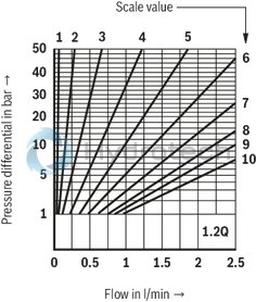
Δp-qV characteristic curves: NG5
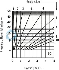
Δp-qV characteristic curves: NG5
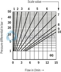
Δp-qV characteristic curves: NG5
Δp-qV characteristic curves: NG10 – linear
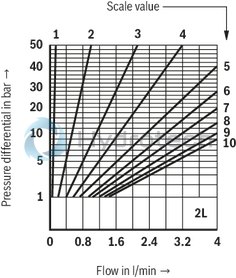
Δp-qV characteristic curves: NG10 – linear
Δp-qV characteristic curves: NG10 – linear
Δp-qV characteristic curves: NG10 – linear
Δp-qV characteristic curves: NG10 – linear
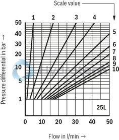
Δp-qV characteristic curves: NG10 – linear
Δp-qV characteristic curves: NG10 – progressive
Δp-qV characteristic curves: NG10 – progressive
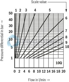
Δp-qV characteristic curves: NG10 – progressive
Δp-qV characteristic curves: NG10 – progressive

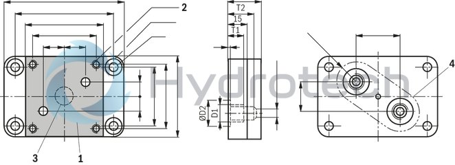
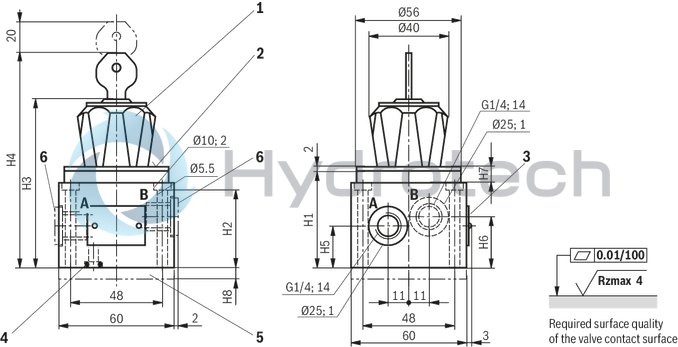
Threaded port and subplate mounting
Dimensions in mm
|
NG |
H1 |
H2 |
H3 |
H4 |
H5 |
H6 |
H7 |
H8 |
|
mm |
mm |
mm |
mm |
mm |
mm |
mm |
mm |
|
| 5 | 56 | 42 | 95 | 122 | 26 | 30 | 12 | 10 |
| 10 | 58 | 42 | 97 | 124 | 22 | 27 | 14 | 10 |
Pipe thread "G" according to ISO 228/1
|
1 |
Rotary knob security lock (all positions can be locked), rotation range 300° corresponds to 10 scale sections |
|
2 |
Scaling |
|
3 |
Name plate |
|
4 |
Seal ring |
|
5 |
Blind plate (with threaded port only) |
|
6 |
Connection bores closed at version "P". |
Valve mounting screws (separate order)
4 hexagon socket head cap screws ISO 4762 - M5 x 50 - 10.9-flZn-240h-L
(friction coefficient μtotal = 0.09 to 0.14);
Tightening torque MA = 7 Nm ± 10 %,
Material no. R913000064
|
NG |
H1 |
H2 |
H3 |
H4 |
|
mm |
mm |
mm |
mm |
|
| 5 | 16 | 93 | 120 | 10.3 |
| 10 | 18 | 95 | 122 | 12.4 |
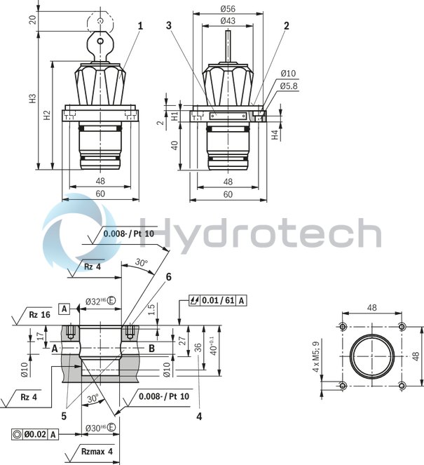
for block installation
Dimensions in mm
|
1 |
Rotary knob security lock (all positions can be locked), rotation range 300° corresponds to 10 scale sections |
|
2 |
Scaling |
|
3 |
Name plate |
|
4 |
Depth of fit |
|
5 |
Attention! Install port A and B outside the range of the mounting bores M5 – Risk of breaking! |
|
6 |
NG5: 4 hexagon socket head cap screws ISO 4762 - M5 x 16 - 10.9-flZn-240h-L (Friction coefficient μtotal = 0.09 to 0.14); Tightening torque MA = 7 Nm ± 10 % Material no. R913000468 |
|
NG10: 4 hexagon socket head cap screws ISO 4762 - M5 x 20 - 10.9-flZn-240h-L (Friction coefficient μtotal = 0.09 to 0.14); Tightening torque MA = 7 Nm ± 10 % Material no. R913000488 |
Dimensions in mm