BOSCH REXROTH
0811405139
$3,193.71 USD
- BOSCH REXROTH
- Material:0811405139
- Model:VT-MACAS-500-10/V0 GO2
Quantity in stock: 0
The Bosch Rexroth VT-MACAS-500-10/V0 (0811405139) is a sophisticated control module designed for precision management of valves with integrated electronics that facilitate both position and velocity control. This module is engineered to be easily mounted onto carrier rails, ensuring a secure and streamlined installation process. It features an enable input that ensures operational safety and efficiency, as well as a cable break detection system that monitors the actual value cable for continuity and integrity, safeguarding against potential system failures. With short-circuit-proof interfaces, the VT-MACAS-500-10/V0 guarantees reliable performance even in demanding environments. The front plate of the module is equipped with test points, providing technicians with convenient access for system diagnostics and maintenance. Additionally, this module offers the flexibility to switch off the compensation jump based on specific application requirements. In terms of control capabilities, the unit provides PT1 control for position adjustments and can also perform velocity control when paired with a tachometer or speed indicator through its PI control function. This adaptability makes it suitable for a variety of applications where precise adjustment of area adjustment cylinders is necessary. Overall, Bosch's VT-MACAS-500-10/V0 stands out as a versatile and robust solution for controlling sophisticated valve systems requiring high levels of accuracy in both position and velocity adjustments. Its design considerations ensure that it can be incorporated into diverse operational setups while maintaining reliability and ease of use for technical personnel.
|
01 |
02 |
03 |
04 |
05 |
06 |
07 |
08 |
09 |
10 |
||||
|
VT- |
M |
A |
C |
A |
S |
– |
500 |
– |
1X |
/ |
V0 |
/ |
|
01 |
VT- |
|
|
02 |
M |
|
|
Hydraulic component |
||
|
03 |
Axis control |
A |
|
Type |
||
|
04 |
Controller |
C |
|
Control |
||
|
05 |
Analog |
A |
|
Function |
||
|
06 |
Position control |
S |
|
Serial number for types |
||
|
07 |
Standard variant without valve amplifier function |
500 |
|
08 |
Component series 10 ... 19 (10 ... 19: unchanged technical data and pin assignment) |
1X |
|
Customer version |
||
|
09 |
Catalog version |
V0 |
|
Option |
||
|
10 |
Marking variant with voltage input |
I |
|
Variant with current input |
Without |
|
General
|
Power supply |
nominal 24 V= battery voltage 21...40 V, rectified alternating voltage Ueff = 21...28 V (single-phase, full-wave rectifier) |
|||
|
Current consumption, max. |
mA |
200 | ||
|
Signal input |
VT-MACAS-500-10/V0 |
Ucommand: ±10 V, differential amplifier Ri= 100 kΩ |
||
|
VT-MACAS-500-10/V0/l |
Iist: 4...20 mA Rsh = 200 Ω |
|||
|
Actual value signal |
VT-MACAS-500-10/V0 |
Uactual: ±10 V, differential amplifier Ri= 100 kΩ |
||
|
VT-MACAS-500-10/V0/l |
Iist: 4...20 mA Rsh = 200 Ω |
|||
|
Valve signal |
UV= ±10 V (max. 10 mA) or IV= 4...20 mA (middle 12 mA) |
|||
|
Compensation step |
can be switched off; effective in a range of ±4 % |
|||
|
Enable signal |
V= |
8,5...40 V | ||
|
Error message |
no error: 24 Vnom (UB) max. 50 mA error: < 2 V |
|||
|
IN POS message |
IN POS: 24 Vnom (UB) max. 50 mA not IN POS: < 2 V |
|||
|
Ramp ranges |
I: 0,1...1 s II: 1...10 s |
|||
|
Area adjustment AK : AR |
min. 1:1; max. 1:4 | |||
|
Actual value adjustment |
Zero point: -5...10 % Gain: 50...110 % |
|||
|
Controller type |
Position: PT1 Velocity: PI |
|||
|
Zero point valve |
% |
± 5 | ||
|
Special features |
– Switchable from position to velocity control – Switchable position window – Test points on front plate – Interfaces short-circuit-proof |
|||
|
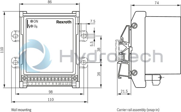
Fastening |
Top hat rail TH35-7.5 or G rail G32 according to EN 60715 | |||
|
Connection |
Connectors + terminals | |||
|
Operating temperature |
°C |
0 … +70 | ||
|
Storage temperature range |
°C |
-20 … +70 | ||
|
Weight |
m |
kg |
0.38 | |
For applications outside these parameters, please consult us!
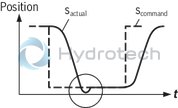
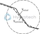
Ideal development (without command value ramps)
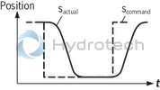
"Overshooting“, p gain too high, → Rotate switch KP against 1
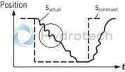
"Creeping into the position“, p gain too low, → Rotate switch KP against 16

"Vibrations“, time constant too small, → Rotate switch KT1 against 16
"Area ratio wrong"; set symmetric motion sequence by means of switch A/B
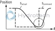
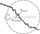
Ideal development (without command value ramps)
P gain too small, → Rotate switch KP against 16
P gain too large, → Rotate switch KP against 1
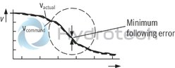
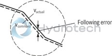
P gain correct, however following error too large, minimization of the following error by means of the I controller → Rotate switch KI until the min. following error is reached
Front plate
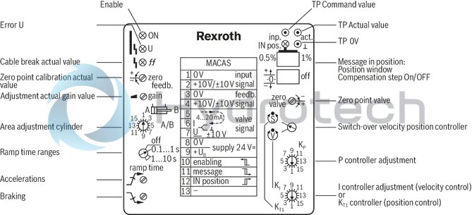
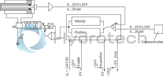
Block diagram with pin assignment
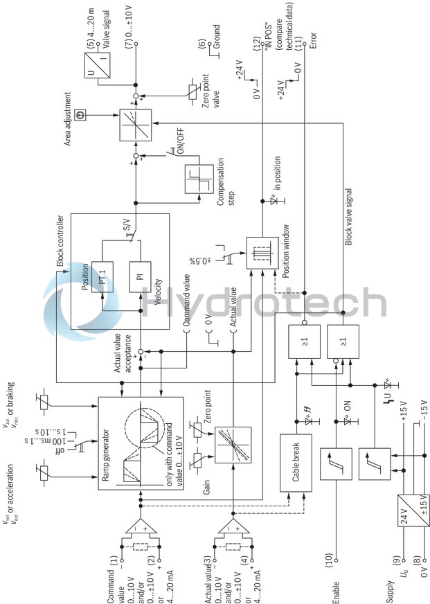
Wiring diagram AVPC-V
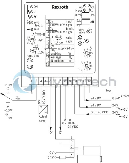
D* valve signal for valve with voltage or current interface
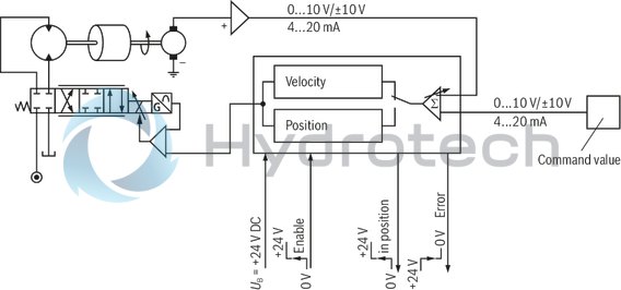
Wiring diagram AVPC-mA
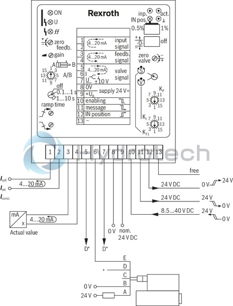
D* valve signal for valve with voltage or current interface
Dimensions in mm