

BOSCH REXROTH
R181024051
$2,806.85 USD
- BOSCH REXROTH
- Material:R181024051
- Model:UBPS-2505-BS1A
Quantity in stock: 0
The Bosch Rexroth BRAKING ELEMENT UBPS 2505 BS1A (R181024051) is a sophisticated pneumatic braking unit designed to provide dynamic and static stabilization in the axial direction for roller rail systems. This high-performance component boasts a solid, rigid steel housing that is chemically nickel-plated, ensuring durability and resistance to wear. It is engineered for compatibility with DIN standards and can be used on all SNS roller guide rails, making it versatile for various applications. With the capability of up to 1 million clamping cycles and up to 250,000 emergency braking operations, this braking element ensures reliability and longevity in demanding operational conditions. Its integrated all-around sealing contributes to its maintenance-free nature, while the mechanical gate valve gear mechanism facilitates high continuous output and precise positioning accuracy. The UBPS 2505 BS1A operates efficiently with extremely low air consumption and includes an integrated quick-exhaust valve for rapid reaction times. The clamping profiles can be held apart by compressed air allowing free movement when necessary. It provides very high axial holding forces of up to 25 kN at 5 bar release pressure with a high-power spring energy accumulator. Additionally, the holding force can be increased up to 50 kN through additional pressurization on the Airplus port. This braking element operates within a permissible ambient temperature range of -30°C to +80°C and has been designed with a focus on safety; in the event of a pressure drop, it generates clamping or braking effect via a dual-acting gate valve gear mechanism equipped with spring assemblies as energy accumulators. The UBPS 2505 BS1A is suitable for various profiled rail systems including sizes A, B, E, H, N, d, and S thread diameter profiled rail systems M6. It has a nominal size indication and weighs approximately 2.7 kg. The functional principle of this unit relies on air pressure ranging from 4 bar (for clamping and braking with spring force) to 6 bar (for decompression with air pressure), offering flexibility according to operational requirements.
Pneumatic braking unit UBPS, 25
Pneumatic braking unit UBPS, FLS for roller rail systems
Size = 25
Can be used on all SNS roller guide rails
Unpacked Weight: 1.080 kg
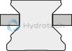
Functional principle
Air pressure: 0 bar
Clamps and brakes with spring force
In the event of a pressure drop, the clamping or braking effect is generated via a dual acting gate valve gear mechanism, each with one spring assembly (spring energy accumulator).
An integrated quick-exhaust valve provides for short reaction times.
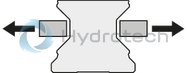
Air pressure: 4.5 - 8 bar (MBPS)
5.5 - 8 bar (UBPS)
Decompression with air pressure
The clamping profiles are held apart by the compressed air.
Free movement is possible
| Dynamic and static stabilization in the axial direction |
| Compact design, compatible with DIN 645 |
| Integrated all-round sealing |
| High positioning accuracy |
| Solid, rigid steel housing, chemically nickel-plated |
| Can be used on all SNS roller guide rails |
| Up to 2,000 emergency braking operations |
| Integrated all-round sealing |
| High continuous output |
| High positioning accuracy |
| Mechanical gate valve gear mechanism |
| Solid, rigid steel housing, chemically nickel-plated |
| Extremely low air consumption |
| Maintenance-free |
| 5 million clamping cycles (B10d value) – the B10d value is not attained with the PLUS connection |
| Can be used on all SNS roller guide rails |
| Very high axial holding forces of up to 7700 N at 5.5 bar release pressure with high-power spring energy accumulator |
| Increased holding force of up to 9,200 N thanks to additional pressurization on the air-plus port |
| 3D CAD | Download 3D CAD |
| 3D CAD | Download 3D CAD |
| Manual | Download Manual |
| Manual | Download Manual |
| Manual | Download Manual |
| Manual | Download Manual |
| Manual | Download Manual |
| Manual | Download Manual |
| Manual | Download Manual |
| Manual | Download Manual |
| Manual | Download Manual |
| Manual | Download Manual |
| Size B1 | 99 |
| Size H (profiled rail system) | 36 |
| Height of runner block | 31 |
| Air consumption (normal liter) standard air port | 0.08 |
| Footnote for spring energy holding force with air-plus port | Increased holding force by additional air admission at air-plus port with 6.0 bar. Switching via 5/2 or 5/3-way directional control valve. |
| Productgroup ID | 17 |
| Size E3 (profiled rail systems) | 20 |
| Size S3 thread diameter (profiled rail systems) | M6 |
| Spring energy holding force with standard air port | 1500 |
| Size E2 (profiled rail systems) | 45 |
| Permissible ambient temperature (max) | |
| Permissible ambient temperature | 0 °C ... +70 °C |
| Footnote for spring energy holding force with standard air port | Holding force achieved by spring energy. The inspection is done in a mounted state with a lubricated layer (ISO-VG 68). |
| Size A (profiled rail systems) | 70 |
| Size F1 | 6.5 |
| Size F2 | 11 |
| Permissible ambient temperature (min) | |
| Width of runner block | 70 |
| Size d (profiled rail systems) | 5.5 |
| Spring energy holding force with air-plus port footnote 2 | Increased holding force by additional air admission at air-plus port with 6.0 bar. Switching via 5/2 or 5/3-way directional control valve. |
| Size N3 (profiled rail systems) | 7 |
| Height of runner block with guide rail | 36 |
| Spring energy holding force with air-plus port | 2650 |
| Air consumption (normal liter) air-plus port | 0.165 |
| Linear guide type | Accessories for profiled rail systems |
| Release pressure min. | 5.5 |
| Size E6 | 20 |
| Type clamping and braking units | Pneumatic |
| Max. pneumatic operating pressure: | 8 |
| Size E1 (profiled rail systems) | 57 |
| Footnote size H1 | For roller runner block .H. (...High...) Spacer plate necessary. |
| Size N4 (profiled rail systems) | 7 |
| Accessories for profiled rail systems | Clamping and braking units |
| Size S2 thread diameter (profiled rail systems) | M8 |
| Weight | 1.080 |
| Size H1 (profiled rail systems) | 31 |
| Nominal size | 25 |

General technical data
|
Size |
25 | 35 | 45 | 55 | |
|
Spring energy holding force with standard air port 1) |
N |
1850 | 2800 | 5200 | 7700 |
|
Spring energy holding force with air-plus port 1) 2) |
N |
2650 | 3800 | 7600 | 9200 |
|
Air consumption (normal liter) standard air port |
dm³/stroke |
0.08 | 0.139 | 0.153 | 0.554 |
|
Air consumption (normal liter) air-plus port |
dm³/stroke |
0.165 | 0.303 | 0.483 | 0.952 |
|
Max. pneumatic operating pressure |
bar |
8 | |||
|
Release pressure min. |
bar |
5.5 | |||
|
Mass |
kg |
1.2 | 2.25 | 6.2 | 9.4 |
|
Operating conditions |
|||||
|
Size |
25 | 35 | 45 | 55 | |
|
Permissible ambient temperature (min ... max) |
0 °C ... +70 °C | ||||
| 1) | Holding force by spring energy. The inspection is done in a mounted state with a lubricated layer (ISO-VG 68). |
| 2) | Increased holding force by additional air admission at air-plus port with 6.0 bar. Circuit across 5/2- or 5/3-way directional control valve. |
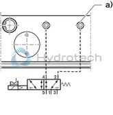
Circuit1) with standard air connection
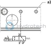
1) Holding force by spring energy. The inspection is done in a mounted state with a lubricated layer (ISO-VG 68).
a) Air filter
1 Air connection
2 Working connection
3 Exhaust
Circuit1) for air-plus port
1) Increased holding force by additional air admission at air-plus port with 6.0 bar. Circuit across 5/2- or 5/3-way directional control valve.
a) Air-plus port
1 Air connection
2 4 Working connections
3 5 Exhaust
Clamping
in the event of loss of pressure during assembly work and standstill of the machine without energy of machine tables from machining centers of z-axis positioning in the resting positionBraking
in the event of energy failure in the event of a pressure drop support of the emergency stop function support as brake for linear motors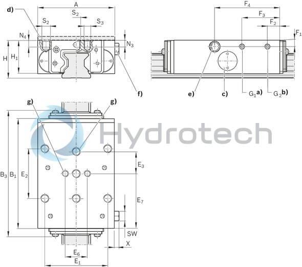
| a) | Air connection*) G1 on two sides for release pressure |
| b) | Connection*) G2 on two sides for air-plus port or air filter |
| c) | Adjusting screw on two sides |
| d) | Spacer plate (accessory) |
| e) | Exhaust on two sides |
| f) | Air filter: Connection G2 (possible on two sides) |
| g) | At least two middle mounting holes must be used! |
| *) Only one connection needed. | |
| All connections sealed upon delivery. |
Dimensions
|
Size |
25 | 35 | 45 | 55 | |
|
A |
mm |
70 | 100 | 120 | 140 |
|
B1 |
mm |
99 | 109 | 199 | 197 |
|
B3max |
mm |
112.3 | 124.8 | 218.4 | 215.8 |
|
E1 |
mm |
57 | 82 | 100 | 116 |
|
E2 |
mm |
45 | 62 | 80 | 95 |
|
E3 |
mm |
20 | 26 | 30 | 35 |
|
E6 |
mm |
20 | 24 | - | |
|
E7 |
mm |
49.5 | 54.5 | 99.5 | 98.5 |
|
F1 |
mm |
6.5 | 8 | 12 | 13 |
|
F2 |
mm |
11 | 32 | ||
|
F3 |
mm |
34.3 | 40.8 | 167 | 165 |
|
F4 |
mm |
59 | 66.5 | 106.5 | 103.5 |
|
G1 |
3 Verstellelemente |
M5 | G1/8" | ||
|
G2 |
3 Verstellelemente |
M5 | G1/8" | ||
|
H |
mm |
36 | 48 | 60 | 70 |
|
H1 1) |
mm |
31 | 42 | 52 | 60 |
|
N3 |
mm |
7 | 10 | - | |
|
N4 |
mm |
7 | 10 | 12 | 14 |
|
S2 |
M8 | M10 | M12 | M14 | |
|
S3 |
M6 | M8 | - | ||
|
SW |
Ø8,SW7 | Ø15,SW13 | |||
|
X |
mm |
5.5 | 6.5 | ||
| 1) | for roller runner block .H. (...high...) Spacer plate necessary. |