

BOSCH REXROTH
R900363511
$483.84 USD
- BOSCH REXROTH
- Material:R900363511
- Model:MK10G1X/V/12
Quantity in stock: 0
The Bosch Rexroth MK10G1X/V/12 (R900363511) is a meticulously engineered throttle check valve designed to regulate fluid flow in hydraulic systems. This valve is specifically tailored for pipeline installation and exhibits a corrosion-protected design, ensuring longevity and reliability in various operational environments. The MK10G1X/V/12 operates as a pressure and viscosity-dependent device, providing precise control over the hydraulic fluid flow. In its throttling direction, the valve functions by utilizing a spring mechanism and the hydraulic fluid itself to press the poppet onto its seat, effectively blocking the connection. The hydraulic fluid is then directed through lateral bores to a throttling point located between the housing and an adjustable sleeve. This design allows for fine-tuning of the flow rate as needed for specific applications. Conversely, when the flow direction is reversed, pressure on the poppet's front face causes it to lift from its seat, permitting free flow through the valve without any throttling effect. An added feature of this valve is its self-cleaning capability; as some of the hydraulic fluid passes through an annular gap during operation, it helps prevent build-up of contaminants. The Bosch Rexroth MK10G1X/V/12 valve is distinguished by its robust construction and performance specifications including a maximum operating pressure (bar) and maximum flow rate (l/min), which are indicative of its suitability for handling demanding tasks while maintaining efficiency and effectiveness in controlling fluid dynamics. It stands out as an essential component for systems requiring precise control over one-way throttled fluid movement with unimpeded return flow.
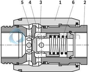
The valves type MK are pressure- and viscosity-dependent throttle check valves.
If the valve is passed by the flow in throttling direction, the spring (6) and the hydraulic fluid push the poppet (5) on the seat and the connection is blocked. Via lateral bores (3), the hydraulic fluid flow is directed to the throttling point (4) between the housing (2) and the adjustable sleeve (1).
In the opposite direction, the pressure acts on the front face of the poppet (5), lifts it from the seat and releases the flow. The hydraulic fluid flow is released through the valve without throttling.
In this process, simultaneous passing of a part of the hydraulic fluid via the annular gap leads to the desired effect of self-cleaning.
|
01 |
02 |
03 |
04 |
05 |
06 |
07 |
|
|
MK |
G |
1X |
/ |
* |
|
01 |
Throttle check valve |
MK |
|
02 |
Size 6 |
6 |
|
Size 8 |
8 |
|
|
Size 10 |
10 |
|
|
Size 15 |
15 |
|
|
Size 20 |
20 |
|
|
Size 25 |
25 |
|
|
Size 30 |
30 |
|
|
03 |
For threaded connection |
G |
|
04 |
Component series 10 ... 19 (10 ... 19: unchanged installation and connection dimensions) |
1X |
|
Corrosion resistance (outside) |
||
|
05 |
None (valve housing primed) |
no code |
|
Improved corrosion protection (240 h salt spray test according to EN ISO 9227) |
J3 |
|
|
Improved corrosion protection (720 h salt spray test according to EN ISO 9227) |
J5 |
|
|
Seal material (observe compatibility of seals with hydraulic fluid used, see "Technical data") |
||
|
06 |
NBR seals |
no code |
|
FKM seals |
V |
|
|
07 |
Further details in the plain text |
* |
Notice:
For valve types for use in potentially explosive areas, refer to data sheet 07011.
general
|
Size |
6 | 8 | 10 | 15 | 20 | 25 | 30 | ||
|
Weight |
kg |
0.3 | 0.4 | 0.7 | 1.1 | 1.9 | 3.2 | 4.1 | |
|
Installation position |
any | ||||||||
|
Ambient temperature |
NBR seals |
°C |
-30 … +80 | ||||||
|
FKM seals |
°C |
-20 … +80 | |||||||
hydraulic
|
Size |
6 | 8 | 10 | 15 | 20 | 25 | 30 | ||
|
Maximum operating pressure |
bar |
315 | |||||||
|
Cracking pressure |
bar |
0.5 | |||||||
|
Maximum flow |
See characteristic curves | ||||||||
|
Leakage flow 1) |
Standard |
l/min |
0.8 | 1 | 2 | 3 | 4 | 5.5 | |
|
Version "J3" and "J5" |
l/min |
1.6 | 2.5 | 3.2 | 3.5 | 7 | 7.7 | ||
|
Hydraulic fluid |
see table "Hydraulic fluid" | ||||||||
|
Hydraulic fluid temperature range |
NBR seals |
°C |
-30 … +80 | ||||||
|
FKM seals |
°C |
-20 … +80 | |||||||
|
Viscosity range |
mm²/s |
10 … 800 | |||||||
|
Maximum admissible degree of contamination of the hydraulic fluid, cleanliness class according to ISO 4406 (c) 2) |
Class 20/18/15 | ||||||||
|
Load cycles |
million |
10 | 2 | ||||||
| 1) | If valve is completely closed |
| 2) | The cleanliness classes specified for the components must be adhered to in hydraulic systems. Effective filtration prevents faults and simultaneously increases the life cycle of the components. For the selection of the filters, see www.boschrexroth.com/filter. |
|
Hydraulic fluid |
Classification |
Suitable sealing materials |
Standards |
Data sheet |
|
|
Mineral oils |
HL, HLP |
NBR, FKM |
DIN 51524 |
90220 |
|
|
Bio-degradable 1) |
Insoluble in water |
HETG |
FKM |
ISO 15380 |
90221 |
|
HEES |
FKM |
||||
|
Soluble in water |
HEPG |
FKM |
ISO 15380 |
||
|
Flame-resistant |
Water-free |
HFDU (glycol base) |
FKM |
ISO 12922 |
90222 |
|
HFDU (ester base) 1) |
FKM |
||||
|
HFDR |
FKM |
||||
|
Containing water 1) |
HFC (Fuchs Hydrotherm 46M, Fuchs Renosafe 500, Petrofer Ultra Safe 620, Houghton Houghto Safe 620, Union Carbide HP5046) |
NBR |
ISO 12922 |
90223 |
|
|
Important information on hydraulic fluids: For more information and data on the use of other hydraulicfluids, please refer to the data sheets above or contact us. There may be limitations regarding the technical valve data (temperature, pressure range, life cycle, maintenance intervals, etc.). The ignition temperature of the hydraulic fluid used must be 50 K higher than the maximum surface temperature. Flame-resistant - containing water: Maximum pressure differential 210 bar, otherwise, increased cavitation erosion Life cycle as compared to operation with mineral oil HL, HLP 30 … 100%. Maximum hydraulic fluid temperature 60 °C Bio-degradable and flame-resistant – containing water: If this hydraulic fluid is used, small amounts of dissolved zinc may get into the hydraulic system. |
|||||
| 1) | Not recommended for corrosion-protected version "J3" and "J5" (contains zinc) |
For applications outside these parameters, please consult us!
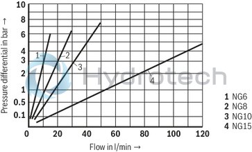
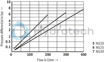
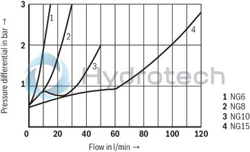
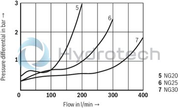
(measured with HLP46, ϑOil = 40 ±5 °C)
Δp-qV characteristic curves via open throttle
Δp-qV characteristic curves via open throttle
Δp-qVcharacteristic curves via open check valve with closed throttle
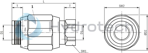
Type MK

Dimensions in mm
|
1 |
Valve marking on key face |
|
NG |
D1 |
ØD2 |
L |
SW1 |
SW2 |
T |
|
mm |
mm |
mm |
mm |
mm |
||
| 6 | G1/4 | 34 | 65 | 22 | 32 | 12 |
| 8 | G3/8 | 38 | 65 | 24 | 36 | 12 |
| 10 | G1/2 | 48 | 80 | 30 | 46 | 14 |
| 15 | G3/4 | 58 | 100 | 41 | 55 | 16 |
| 20 | G1 | 72 | 110 | 46 | 70 | 18 |
| 25 | G1 1/4 | 87 | 130 | 55 | 85 | 20 |
| 30 | G1 1/2 | 93 | 150 | 60 | 90 | 22 |