

BOSCH REXROTH
R900430077
$240.00 USD
- BOSCH REXROTH
- Material:R900430077
- Model:M-SR8KE50-1X/V
Quantity in stock: 0
The Bosch Rexroth M-SR 8 KE50-1X/V (R900430077) is a high-performance check valve designed for hydraulic applications requiring leakage-free blocking in one direction. This direct-acting cartridge valve is part of the MSR product family, known for its reliability and efficiency in controlling fluid flow. It features a poppet-type spool, ensuring tight sealing with FKM material to maintain system integrity even under high pressure conditions. With its nominal flow and maximum flow capabilities, the M-SR 8 KE50-1X/V valve can handle demanding hydraulic circuits while maintaining stability and performance. It operates at a maximum pressure that ensures it can be integrated into systems with varying pressure requirements without pressure presetting. The valve's design allows for installation in block designs, serving as an angle valve or straight-through valve depending on the application's needs. The versatility of the M-SR 8 KE50-1X/V extends to its compatibility with various hydraulic fluids including HL, HLP, HETG, HEES, HEPG, and HFDU types, making it suitable for a wide range of hydraulic systems. Various cracking pressures are available as optional features to cater to specific operational demands. This model falls under Component series X, indicating its place within Bosch Rexroth's lineup of advanced hydraulic components. Overall, the Bosch Rexroth M-SR 8 KE50-1X/V offers reliable performance for systems that require precise control over fluid flow direction while preventing backflow in one direction. Its robust construction and flexibility make it an essential component in modern hydraulic applications.
Unpacked Weight: 0.0278 kg
| Maximum operating pressure 420 bar (6000 psi) |
| Maximum flow 35 l/min (9,3 gpm) |
| Max. pressure | 420 |
| Product family classification | Check valve, cartridge design |
| Productgroup ID | 9,10,11,12,13,14 |
| Product family type | M-SR |
| Ports number | 2 |
| Sealing material | FKM |
| Pressure setting | 5 |
| Product type | M-SR |
| Max. flow | 35 |
| Nominal flow | 35 |
| Pressure pre-setting | Without pressure pre-setting |
| Direct - Pilot | Direct acting |
| Product family | Check |
| Spool Poppet | Poppet type |
| Weight | 0.0278 |
| Hydraulic fluid | HL,HLP,HETG,HEES,HEPG,HFDU |
| Hydraulic fluid | HL,HLP,HETG,HEES,HEPG,HFDU |
|
01 |
02 |
03 |
04 |
|
05 |
06 |
|
07 |
08 |
|
M-SR |
|
|
|
– |
1X |
|
/ |
|
* |
|
01 |
Check valve, cartridge design |
M-SR |
|
Size |
||
|
02 |
Size 6 (not version "KE") |
6 |
|
Size 8 |
8 |
|
|
Size 10 |
10 |
|
|
Size 15 |
15 |
|
|
Size 20 |
20 |
|
|
Size 25 |
25 |
|
|
Size 30 |
30 |
|
|
Unit design |
||
|
03 |
Angle valve |
KE |
|
Straight-through valve |
KD |
|
|
Cracking pressure |
||
|
04 |
0 bar, without spring (not version "KD") |
00 |
|
0,2 bar |
02 |
|
|
0.5 bar (standard) |
05 |
|
|
1,5 bar |
15 |
|
|
3,0 bar |
30 |
|
|
5,0 bar |
50 |
|
|
05 |
Component series 10 ... 19 (10 ... 19: unchanged installation and connection dimensions) |
1X |
|
Orifice in channel B (version "KD" only) |
||
|
06 |
Without orifice |
no code |
|
Core hole M4 |
B00 |
|
|
Nozzle Ø 1.0 mm |
B10 |
|
|
Nozzle Ø 1.2 mm |
B12 |
|
|
Seal material (observe compatibility of seals with hydraulic fluid used, see "Technical data") (version "KE" only) |
||
|
07 |
NBR seals |
no code |
|
FKM seals |
V |
|
|
08 |
Further details in the plain text |
* |
general
|
Size |
6 | 8 | 10 | 15 | 20 | 25 | 30 | ||
|
Weight |
Angle valve "KE" |
kg |
- | 0.03 | 0.05 | 0.08 | 0.14 | 0.32 | 0.47 |
|
Straight-through valve "KD" |
kg |
0.05 | 0.1 | 0.2 | 0.25 | 0.3 | |||
|
Installation position |
any | ||||||||
|
Ambient temperature range |
NBR seals |
°C |
-20 … +80 | ||||||
|
FKM seals |
°C |
-20 … +80 | |||||||
|
MTTFD values according to EN ISO 13849 1) |
150 Years | ||||||||
| 1) | For further details, see data sheet 08012 and 90294 |
hydraulic
|
Size |
6 | 8 | 10 | 15 | 20 | 25 | 30 | ||
|
Maximum operating pressure |
bar |
420 | |||||||
|
Cracking pressure |
See characteristic curves | ||||||||
|
Maximum flow |
l/min |
15 | 35 | 50 | 120 | 200 | 300 | 400 | |
|
Hydraulic fluid |
see table "Hydraulic fluid" | ||||||||
|
Hydraulic fluid temperature range |
NBR seals |
°C |
-30 … +80 | ||||||
|
FKM seals |
°C |
-20 … +80 | |||||||
|
Viscosity range |
mm²/s |
2.8 … 500 | |||||||
|
Maximum admissible degree of contamination of the hydraulic fluid, cleanliness class according to ISO 4406 (c) 1) |
Class 20/18/15 | ||||||||
| 1) | The cleanliness classes specified for the components must be adhered to in hydraulic systems. Effective filtration prevents faults and simultaneously increases the life cycle of the components. For the selection of the filters, see www.boschrexroth.com/filter. |
|
Hydraulic fluid |
Classification |
Suitable sealing materials |
Standards |
Data sheet |
|
|
Mineral oils |
HL, HLP |
NBR, FKM |
DIN 51524 |
90220 |
|
|
Bio-degradable |
Insoluble in water |
HETG |
FKM |
ISO 15380 |
90221 |
|
HEES |
FKM |
||||
|
Soluble in water |
HEPG |
FKM |
ISO 15380 |
||
|
Flame-resistant |
Water-free |
HFDU (glycol base) |
FKM |
ISO 12922 |
90222 |
|
HFDU (ester base) |
FKM |
||||
|
Containing water |
HFC (Fuchs Hydrotherm 46M, Petrofer Ultra Safe 620) |
NBR |
ISO 12922 |
90223 |
|
|
Important information on hydraulic fluids: For more information and data on the use of other hydraulicfluids, please refer to the data sheets above or contact us. There may be limitations regarding the technical valve data (temperature, pressure range, life cycle, maintenance intervals, etc.). Flame-resistant - containing water: Life cycle as compared to operation with mineral oil HL, HLP 30 … 100%. Maximum hydraulic fluid temperature 60 °C |
|||||
For applications outside these parameters, please consult us!
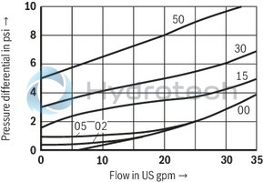
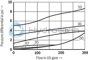
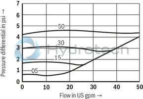
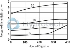
Angle valve (measured with HLP46, ϑOil = 40 ±5 °C)
Pressure differential Δp dependent on the flow qV at cracking pressure
Size 8
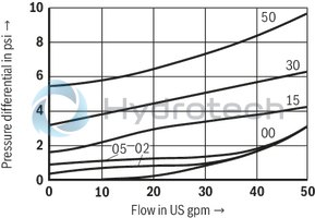
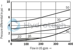
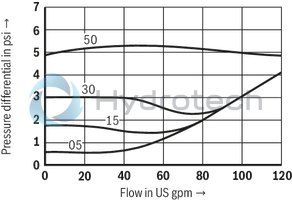
Pressure differential Δp dependent on the flow qV at cracking pressure
Size 10
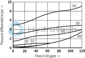
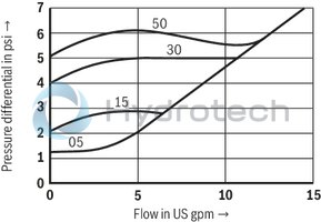
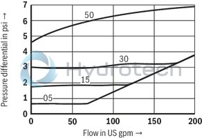
Pressure differential Δp dependent on the flow qV at cracking pressure
Size 15
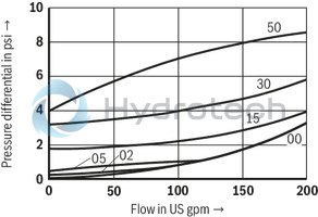
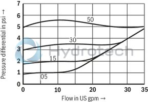
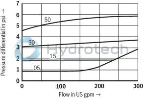
Pressure differential Δp dependent on the flow qV at cracking pressure
Size 20
Pressure differential Δp dependent on the flow qV at cracking pressure
Size 25
Pressure differential Δp dependent on the flow qV at cracking pressure
Size 30
Straight-through valve (measured with HLP46, ϑOil = 40 ±5 °C)
Pressure differential Δp dependent on the flow qV at cracking pressure
Size 6
Pressure differential Δp dependent on the flow qV at cracking pressure
Size 8
Pressure differential Δp dependent on the flow qV at cracking pressure
Size 10
Pressure differential Δp dependent on the flow qV at cracking pressure
Size 15
Pressure differential Δp dependent on the flow qV at cracking pressure
Size 20
Pressure differential Δp dependent on the flow qV at cracking pressure
Size 25
Pressure differential Δp dependent on the flow qV at cracking pressure
Size 30
With spring

Without spring

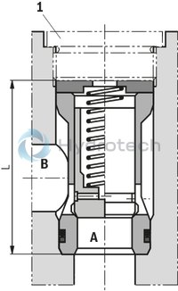
Angle valve "KE"
Dimensions in mm
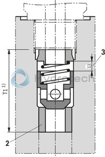
Straight-through valve "KD"
Dimensions in mm
| 1) | For dimensions, see installation bores |
|
NG |
L-0,1 |
|
mm |
|
| 6 | - |
| 8 | 36.3 |
| 10 | 39.3 |
| 15 | 45.8 |
| 20 | 55.3 |
| 25 | 74.3 |
| 30 | 83.3 |
|
1 |
Plug screws, separate order, see "Accessories" |
|
2 |
Seat with -60 °C shrink-fitted |
|
3 |
Poppet stroke |
Installation bores
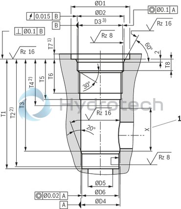
Installation bore: Angle valve "KE" – plug screw according to ZN 10001
Dimensions in mm
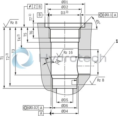
| 1) | Dimensions for countersinking the screw head. For lower installation of the installation kit, dimension T7 has to be extended accordingly. |
| 2) | Depth of fit |
| 3) | Pipe thread "G" according to ISO 228/1 |
|
1 |
Range for outlet bore |
|
NG |
pN |
ØD1 |
ØD2 |
D3 |
ØD4H8 |
ØD5 |
ØD6H7 |
T1 |
T2 |
T3 |
T4 |
T5 |
T6 |
T7 |
X |
Z |
||
|
bar |
mm |
mm |
mm |
mm |
mm |
mm |
mm |
mm |
mm |
mm |
mm |
mm |
mm |
mm |
mm |
mm |
||
| 8 | 420 | 23 | 17.1 | G3/8 | 14 | 8 | 13 | 48.5 | + 0.1 | 47.5 | 38.5 | 20 | 15 | 12 | 6 | + 0.5 | 18 | 0.05 |
| 10 | 420 | 28 | 21.4 | G1/2 | 18 | 10 | 17 | 53.5 | + 0.1 | 52.5 | 43.5 | 24 | 18 | 14 | 6 | + 0.5 | 19 | 0.05 |
| 15 | 420 | 33 | 26.8 | G3/4 | 24 | 15 | 22 | 62 | + 0.1 | 60.5 | 50 | 26 | 20.5 | 16 | 6 | + 0.5 | 24 | 0.05 |
| 20 | 420 | 41 | 33.8 | G1 | 30 | 20 | 28 | 71.5 | + 0.1 | 70 | 56.5 | 26 | 20.5 | 16 | 7 | + 0.5 | 30 | 0.05 |
| 25 | 250 | 51 | 42.5 | G1 1/4 | 38 | 25 | 36 | 90.5 | + 0.1 | 88 | 72.5 | 28 | 22 | 16 | 7 | + 0.5 | 43 | 0.1 |
| 30 | 250 | 56 | 48.5 | G1 1/2 | 44 | 30 | 42 | 99.5 | + 0.1 | 96.5 | 79.5 | 31 | 22 | 16 | 7 | + 0.5 | 48 | 0.1 |
Notice:
Plug screws, separate order, see "Accessories"
Oiling of plug screws prior to installation is recommended.
Installation bore: Angle valve – plug screw according to RN 143.28 – up to 315 bar
Dimensions in mm
| 1) | Dimensions for countersinking the screw head. For lower installation of the installation kit, dimension T7 has to be extended accordingly. |
| 2) | Depth of fit |
| 3) | Metric ISO fine thread according to DIN 13 |
|
1 |
Range for outlet bore |
|
NG |
pN |
ØD1 |
ØD2H8 |
D3 |
ØD4H8 |
ØD5 |
ØD6H7 |
T1 |
T2 |
T3 |
T4 |
T5 |
T6 |
T7 |
T8 |
X |
||||
|
bar |
mm |
mm |
mm |
mm |
mm |
mm |
mm |
mm |
mm |
mm |
mm |
mm |
mm |
mm |
mm |
mm |
mm |
mm |
||
| 25 | 315 | 56 | + 0.5 | 44 | M42 x 1,5 | 38 | 25 | 36 | 106.5 | + 0.1 | 104 | 88.5 | 45 | 39 | 33 | 5 | + 0.5 | 12 | + 0.2 | 43 |
| 30 | 315 | 62 | + 0.5 | 50 | M48 x 1,5 | 44 | 30 | 42 | 115.5 | + 0.1 | 112.5 | 95.5 | 48 | 39 | 33 | 5 | + 0.5 | 12 | + 0.2 | 48 |
Notice:
Plug screws, separate order, see "Accessories"
To be replaced in case of maintenance.
Installation bore: Angle valve – plug screw according to RN 143.28 – up to 420 bar
Dimensions in mm
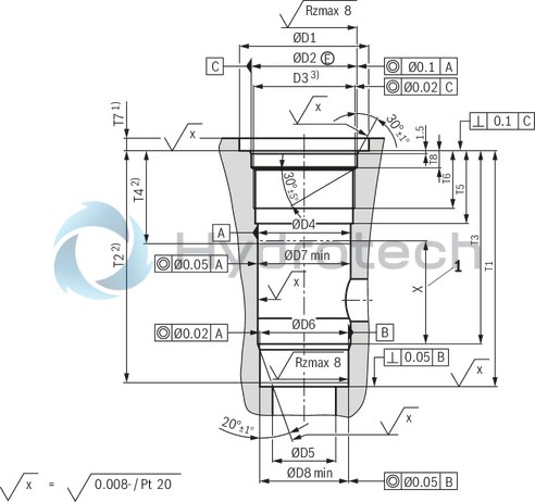
| 1) | Dimensions for countersinking the screw head. For lower installation of the installation kit, dimension T7 has to be extended accordingly. |
| 2) | Depth of fit |
| 3) | Metric ISO fine thread according to DIN 13 |
|
1 |
Range for outlet bore |
|
NG |
pN |
ØD1 |
ØD2H8 |
D3 |
ØD4H8 |
ØD5 |
ØD6H7 |
ØD7 |
ØD8 |
T1 |
T2 |
T3 |
T4 |
T5 |
T6 |
T7 |
T8 |
X |
||||
|
bar |
mm |
mm |
mm |
mm |
mm |
mm |
mm |
mm |
mm |
mm |
mm |
mm |
mm |
mm |
mm |
mm |
mm |
mm |
mm |
mm |
||
| 25 | 420 | 51 | + 0.5 | 44 | M42 x 2 | 38 | 25 | 36 | 37.58 | 35.58 | 101.5 | + 0.1 | 100 | 83.5 | 40 | 34 | 27 | 6 | + 0.5 | 7.8 | + 0.2 | 43 |
| 30 | 420 | 61 | + 0.5 | 50 | M48 x 2 | 44 | 30 | 42 | 43.58 | 41.58 | 110.5 | + 0.1 | 108.5 | 90.5 | 43 | 34 | 27 | 6 | + 0.5 | 7.8 | + 0.2 | 48 |
Notice:
Plug screws, separate order, see "Accessories" Oiling of plug screws prior to installation is recommended. From an operating pressure larger 350 bar, the plug screw has to be glued by means of Loctite 243 over the complete thread circumference.Installation bore: Straight-through valve
Dimensions in mm
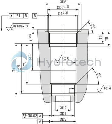
|
NG |
ØD1H7 |
ØD3H8 |
D4 1) |
ØD5 |
D4 2) |
ØD5 |
ØD6 |
T1 |
T2 3) |
T3 |
T4 3) |
T5 |
T6 |
Z |
Poppet stroke |
|||
|
mm |
mm |
mm 1) |
mm |
mm 2) |
mm |
mm |
mm |
mm |
mm |
mm |
mm |
mm |
mm |
mm |
mm |
|||
| 6 | 10 | 11 | G1/4 | 13.6 | ± 0.1 | M14 x 1,5 | 14.4 | ± 0.1 | 25 | 29.8 | - 0.1 | 27.8 | 21.8 | 19 | 12 | 16 | 0.1 | 4 |
| 8 | 13 | 14 | G3/8 | 17.1 | ± 0.1 | M18 x 1,5 | 18.4 | ± 0.1 | 28 | 32.8 | - 0.1 | 30.8 | 22.8 | 18 | 12 | 16 | 0.1 | 4 |
| 10 | 17 | 18 | G1/2 | 21.4 | ± 0.1 | M22 x 1.5 | 22.4 | ± 0.1 | 34 | 38.8 | - 0.1 | 36.8 | 28.8 | 21 | 14 | 19 | 0.1 | 4 |
| 15 | 22 | 24 | G3/4 | 26.8 | ± 0.1 | M27 x 2 | 27.4 | ± 0.1 | 42 | 48.4 | - 0.1 | 46.4 | 36.4 | 27 | 16 | 21 | 0.2 | 5 |
| 20 | 28 | 30 | G1 | 33.8 | ± 0.1 | M33 x 2 | 33.5 | ± 0.1 | 47 | 59 | - 0.1 | 57 | 44 | 29 | 18 | 24 | 0.2 | 5 |
| 25 | 36 | 38 | G1 1/4 | 42.5 | ± 0.1 | M42 x 2 | 42.5 | ± 0.1 | 58 | 73 | - 0.1 | 71 | 55 | 39 | 20 | 26 | 0.2 | 7 |
| 30 | 42 | 44 | G1 1/2 | 48.5 | ± 0.1 | M48 x 2 | 48.5 | ± 0.1 | 65 | 83 | - 0.1 | 81 | 63 | 42 | 22 | 28 | 0.2 | 7 |
| 1) | Pipe thread "G" according to ISO 228/1 |
| 2) | Metric ISO fine thread according to DIN 13 |
| 3) | Depth of fit |
Plug screw according to ZN 10001
|
Size |
Seal material |
Designation |
Material number |
Tightening torques MA ±10 % |
Buy |
Plug screw according to ZN 10001
|
Size |
Seal material |
Designation |
Material number |
Tightening torques MA ±10 % |
Buy |
|
Nm |
|||||
| 8 | NBR | ZN10001-G3/8A-N-ST | R913011602 | 55 | eShop |
| FKM | ZN10001-G3/8A-F-ST | R913011610 | eShop | ||
| 10 | NBR | ZN10001-G1/2A-N-ST | R913011603 | 80 | eShop |
| FKM | ZN10001-G1/2A-F-ST | R913011611 | eShop | ||
| 15 | NBR | ZN10001-G3/4A-N-ST | R913011604 | 135 | eShop |
| FKM | ZN10001-G1 1/2A-F-ST | R913011612 | eShop | ||
| 20 | NBR | ZN10001-G1A-N-ST | R913011605 | 225 | eShop |
| FKM | ZN10001-G1A-F-ST | R913011613 | eShop | ||
| 25 | NBR | ZN10001-G1 1/4A-N-ST | R913011606 | 360 | eShop |
| FKM | ZN10001-G1 1/4A-F-ST | R913011614 | eShop | ||
| 30 | NBR | ZN10001-G1 1/2A-N-ST | R913011607 | 400 | eShop |
| FKM | ZN10001-G1 1/2A-F-ST | R913011615 | eShop |
Plug screw according to RN 143.28 – up to 315 bar
|
Size |
Seal material |
Designation |
Material number |
Tightening torques MA ±10 % |
Buy |
|
Nm |
|||||
| 25 | NBR | M42X1,5-ST/320/NBR | R900323609 | 300 | eShop |
| FKM | M42X1,5-ST/320/FKM | R900301957 | eShop | ||
| 30 | NBR | M48X1,5-ST/320/NBR | R900323610 | 325 | eShop |
| FKM | M48X1,5-ST/320/FKM | R900301958 | eShop |
Plug screw according to RN 143.28 – up to 420 bar
|
Size |
Seal material |
Designation |
Material number |
Tightening torques MA ±10 % |
Buy |
|
Nm |
|||||
| 25 | NBR | M42X2-ST-PRECOTE85/630/NBR | R901183335 | 300 | eShop |
| FKM | M42X2-ST-PRECOTE85/630/FKM | R901253503 | eShop | ||
| 30 | NBR | M48X2-ST-PRECOTE85/630/NBR | R901183336 | 325 | eShop |
| FKM | M48X2-ST-PRECOTE85/630/FKM | R901253504 | eShop |