
BOSCH REXROTH
R900473688
$1,107.00 USD
- BOSCH REXROTH
- Material:R900473688
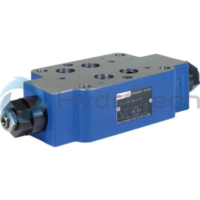
- Model:Z2FS16-8-3X/S2V
Quantity in stock: 0
The Bosch Rexroth Z2FS16-8-3X/S2V (R900473688) is a high-performance industrial hydraulic valve designed for reliable flow throttling to a set value. This direct-actuated sandwich plate valve is part of the ZFS series, known for its capability to limit the flow of one or two actuator ports efficiently. It features two symmetrically arranged throttle check valves that use adjustable throttle spools to manage flow in one direction while allowing free return flow in the opposite direction. The valve's design includes a spindle with an internal hexagon for easy adjustment of the throttle point, ensuring precise control over the hydraulic fluid flow. The model code indicates that it can be used with spool symbols A A, B B or A A, B B, and it is mechanically actuated. With a maximum pressure capacity and compatibility with numerous hydraulic fluids such as HL, HLP, HLPD, HVLP, HVLPD, HETG, HEES, HEPG, HFDU, and HFDR (as specified by seals FKM), this valve demonstrates versatility across various applications. The Z2FS16-8-3X/S2V valve offers meter-in or meter-out throttling and can be installed between the directional valve and the subplate for actuator velocity adjustment. It conforms to NFPA T.. R D and ISO porting patterns standards and can support a maximum operating pressure of up to bar (as per productgroup ID) and a maximum flow rate of l/min. With its robust size CETOP D design and weighing in at . kg., this component promises durability and reliability in controlling fluid dynamics within hydraulic systems.
Size 16, A1 → A2, B1 → B2 or A2 → A1, B2 → B1, mechanically actuated
Industrial hydraulic valve in a high performance range. Reliable throttling of the flow to setting value.
Unpacked Weight: 4.38 kg
The valve type Z2FS is a throttle check valve in sandwich plate design. It is used for the flow limitation of one or two actuator ports.
Two symmetrically arranged throttle check valves limit flows (by adjustable throttle spools) in one direction and allow free return flow in the opposite direction.
In case of supply throttling, the hydraulic fluid is directed through channel A➀ via throttling point (1) to actuator A➁. The throttle spool (2.1) can be axially adjusted via the spindle (3) for adjustment of the throttling point (1).
Simultaneously, the hydraulic fluid in channel A➀ is directed via the bore (4) to the piston side (5).
The active pressure and the spring force retain the throttle spool (2.1) in throttle position.
The hydraulic fluid return flow from actuator B➁ displaces the throttle spool (2.2) and enables the unobstructed flow as check valve. Depending on the version ("S" or "S2"), the throttling effect may occur in supply or discharge.
Flow limitation
For actuator velocity adjustment, the throttle check valve is installed between the directional valve and the subplate.
Supply throttling

|
➀ |
component side |
|
➁ |
plate side |
| Direct actuated |
| Internal hexagon |
| Maximum operating pressure 350 bar |
| Component series 3X |
| Size 16 |
| Maximum flow 250 l/min |
| Data Sheet | Download Data Sheet |
| 3D CAD | Download 3D CAD |
| Manual | Download Manual |
| Manual | Download Manual |
| Manual | Download Manual |
| Manual | Download Manual |
| Manual | Download Manual |
| Spool symbol | A1 → A2, B1 → B2 or A2 → A1, B2 → B1 |
| Max. pressure | 350 |
| Productgroup ID | 9,10,11,12,13,14 |
| Number of ports | 4 |
| Type of actuation | with mechanical actuation |
| Size | 16 |
| Max. flow | 250 |
| Type of connection | Sandwich plate |
| Connection diagram NFPA | NFPA T3.5.1 R2-2002 D07 |
| Size_CETOP | D07 |
| Connection diagram | ISO 4401-07-07-0-05 |
| Number of switching positions | 2 |
| Weight | 4.38 |
| Seals | FKM |
| Hydraulic fluid | HL,HLP,HLPD,HVLP,HVLPD,HETG,HEES,HEPG,HFDU,HFDR |
|
01 |
02 |
03 |
04 |
05 |
06 |
07 |
08 |
09 |
10 |
11 |
||
|
Z |
2 |
FS |
16 |
8 |
– |
3X |
/ |
* |
|
01 |
Sandwich plate valve |
Z |
|
Number of functions |
||
|
02 |
2 (throttling in channel A and/or B) |
2 |
|
03 |
Throttle check valve |
FS |
|
04 |
Size 16 |
16 |
|
Functions in |
||
|
05 |
Channel A |
A |
|
Channel B |
B |
|
|
Channel A and B |
– |
|
|
Adjustment type |
||
|
06 |
Spindle with internal hexagon |
8 |
|
07 |
Component series 30 ... 39 (30 ... 39: unchanged installation and connection dimensions) |
3X |
|
Supply throttling / discharge throttling |
||
|
08 |
Supply throttling on side A ("…A8–3X/S") |
S |
|
Supply throttling on side B ("…B8–3X/S") |
||
|
Supply throttling on side A and B ("…–8–3X/S") |
||
|
Discharge throttling on side A ("…A8–3X/S2") |
S2 |
|
|
Discharge throttling on side B ("…B8–3X/S2") |
||
|
Discharge throttling on side A and B ("…–8–3X/S2") |
||
|
Corrosion resistance (outside) |
||
|
09 |
None (valve housing primed) (standard) |
no code |
|
Improved corrosion protection (240 h salt spray test according to EN ISO 9227) |
J3 |
|
|
Seal material |
||
|
10 |
NBR seals |
no code |
|
FKM seals |
V |
|
|
Observe compatibility of seals with hydraulic fluid used. (Other seals upon request) |
||
|
11 |
Further details in the plain text |
* |
Preferred types and standard units are contained in the EPS (standard price list).
general
|
Size |
16 | ||
|
Weight (approx.) |
kg |
4.7 | |
|
Installation position |
any | ||
|
Ambient temperature range |
NBR seals |
°C |
-30 … +80 |
|
FKM seals |
°C |
-20 … +80 | |
hydraulic
|
Size |
16 | ||
|
Maximum operating pressure |
bar |
350 | |
|
Maximum flow |
l/min |
250 | |
|
Hydraulic fluid |
see table | ||
|
Hydraulic fluid temperature range |
NBR seals |
°C |
-30 … +80 |
|
FKM seals |
°C |
-20 … +80 | |
|
Viscosity range |
mm²/s |
2.8 … 380 | |
|
Maximum admissible degree of contamination of the hydraulic fluid 1) |
Class 20/18/15 according to ISO 4406 (c) | ||
| 1) | The cleanliness classes specified for the components must be adhered to in hydraulic systems. Effective filtration prevents faults and simultaneously increases the life cycle of the components. For the selection of the filters, see www.boschrexroth.com/filter. |
|
Hydraulic fluid |
Classification |
Suitable sealing materials |
Standards |
Data sheet |
|
|
Mineral oils |
HL, HLP |
NBR, FKM |
DIN 51524 |
90220 |
|
|
Bio-degradable |
Insoluble in water |
HEES 2) |
FKM |
ISO 15380 |
90221 |
|
Soluble in water |
HEPG 2) |
FKM |
ISO 15380 |
||
|
Containing water |
Containing water |
HFC (Fuchs Hydrotherm 46M, Petrofer Ultra Safe 620) 2) |
NBR |
ISO 12922 |
upon request |
|
Important information on hydraulic fluids: Further information and information on the use of other hydraulic fluids on request! There may be limitations regarding the technical valve data (temperature, pressure range, life cycle, maintenance intervals, etc.)! The flash point of the hydraulic fluid used must be 40 K higher than the maximum solenoid surface temperature.Flame-resistant – containing water: Maximum pressure differential 210 bar, otherwise increased cavitation Pressure pre-loading at the tank port >20 % of the pressure differential; otherwise, increased cavitation Life cycle compared to operation with mineral oil HL, HLP 30 to 100 % |
|||||
| 2) Not for version "J3" |
For applications outside these parameters, please consult us!
(measured with HLP46, ϑOil = 40 ±5 °C)
Δp-qV characteristic curves (via check valve with closed throttle)


Δp-qV characteristic curves (constant throttle position)


Supply throttling "S"
Version "-"

Discharge throttling "S2"
Version "-"

Discharge throttling "S2"
Version "A"

Discharge throttling "S2"
Version "A"
Supply throttling "S"
Version "B"

Discharge throttling "S2"
Version "B"

|
➀ |
component side |
|
➁ |
plate side |
Supply throttling "S"
Version "A"

Dimensions in mm

Dimensions in mm

|
1 |
Name plate |
|
2 |
Adjustment type "8“ Spindle for changing the flow cross-section (internal hexagon SW6) Left rotation = higher flow Right rotation = lower flow |
|
3 |
Through holes for valve mounting |
|
4 |
Identical seal rings for connection A, B, P, T |
|
5 |
Identical seal rings for ports X, Y, L |
|
6 |
Locking pin (included in the scope of delivery) |
|
7 |
Hexagon SW19, tightening torque MA see table |
|
8 |
Porting pattern according to ISO 4401-07-07-0-05 |
|
9.1 |
Plug screw with version "B" |
|
9.2 |
Plug screw with version "A" |
|
Version “Corrosion resistance” |
L1 |
L2 |
L3 |
L4 |
L5 |
L6 |
Pos. 7 MA in Nm ±10 % |
|
mm |
mm |
mm |
mm |
mm |
mm |
Nm |
|
| "no code" | 224 | 248 | 224 | 248 | 246 | 294 | 25 |
| „J3“ | 227 | 251 | 227 | 251 | 252 | 300 | 33 |
Valve mounting screws (separate order)
metric4 hexagon socket head cap screws ISO 4762 - M10 - 10.9-flZn-240h-L
2 hexagon socket head cap screws ISO 4762 - M6 - 10.9-flZn-240h-L
UNC
4 hexagon socket head cap screws 3/8-16 UNC
2 hexagon socket head cap screws 1/4-20 UNC
Notice:
Length and tightening torque of the valve mounting screws must be calculated according to the components mounted under and over the sandwich plate valve.