

BOSCH REXROTH
R901105144
$8,287.00 USD
- BOSCH REXROTH
- Material:R901105144
- Model:2FRE16-4X/125LK4V
Quantity in stock: 0
The Bosch Rexroth 2FRE16-4X/125LK4V (R901105144) is a high-performance proportional flow control valve designed for precise flow regulation in hydraulic systems. This component is part of the FRE series and boasts a two-way function that allows for pressure and temperature-compensated flow control based on electrical command values. The valve features a robust housing, an inductive position transducer, and a proportional solenoid that together ensure accurate metering orifice adjustments. The pressure compensator within the valve maintains a constant pressure drop across the orifice, ensuring stable flow regardless of system pressure fluctuations. The 2FRE16-4X/125LK4V is equipped with a stroke limitation mechanism to enhance response times when operating at flows significantly less than its maximum rated capacity, minimizing startup jumps. Additionally, the design incorporates a check valve for free return flow from B to A, and can be paired with an additional rectifier sandwich plate for bidirectional flow control. For ease of calibration and maintenance, the valve features an axially movable position transducer coil allowing straightforward zero-point calibration without affecting the control electronics. The low manufacturing tolerance of both the valve and its electrical amplifier module ensures consistent performance and reliability. This model is designed for subplate mounting with porting patterns according to ISO standards. With its size 16 component series X, the 2FRE16-4X/125LK4V can withstand a maximum operating pressure of up to 315 bar and can manage flows up to 125 liters per minute. Its advanced features make it suitable for applications requiring precise flow management under varying pressure conditions while maintaining low temperature drift and smooth startup capabilities.
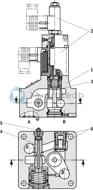
Proportional flow control valves of the 2FRE ... type comprise a 2-way function. They are capable of controlling a flow indicated by the electrical command value in a pressure- and largely temperature-compensated manner.
The set-up basically consists of a housing (1), proportional solenoid with inductive position transducer (2), metering orifice (3), pressure compensator (4), stroke limitation (5) as well as check valve (6). The flow setting is determined by the indication (0 to 100%) at the command value potentiometer. Via the amplifier as well as the proportional solenoid, the indicated command value has an effect on the adjustment of the metering orifice (3). The position of the metering orifice (3) is recorded by the inductive position transducer. Any existing variations from the command value are corrected by the position control.
The pressure compensator (4) keeps the pressure drop at the metering orifice (3) at a constant value at all times. Thus, the flow is pressure-compensated.
If the flow controller is only used within a range which is considerably smaller than the maximum intended rated flow of the valve, the response time of the pressure compensator (4) may be shortened by limiting the pressure compensator stroke. This allows for the reduction of unwanted start-up jumps.
If the grub screw at the stroke limitation (5) is at the left stop (screwed out), there is no pressure compensator stroke limitation.
The low temperature drift is the result of the favorable design of the metering orifice.
With command value 0%, the metering orifice is closed. In the event of a power failure or cable break at the inductive position transducer, the metering orifice closes.
From the command value 0%, a smooth start-up is possible. Via two ramps in the electric amplifier, the metering orifice can be opened and closed with delay.
Via the check valve (6), a free return flow from B to A is possible. With an additional rectifier sandwich plate of the Z4S... type under the proportional flow control valve, the supply and return flow from the actuator can be regulated.
|
01 |
02 |
03 |
04 |
05 |
06 |
07 |
08 |
||
|
2FRE |
- |
4X |
/ |
B |
K4 |
* |
|
01 |
Proportional flow control valve in 2-way version |
2FRE |
|
|
02 |
Size 10 |
10 |
|
|
Size 16 |
16 |
||
|
03 |
Component series 40 … 49 (40 … 49: unchanged installation and mounting dimensions) |
4X |
|
|
Rated flow A → B, flow characteristics |
|||
|
04 |
Size 10 |
||
|
Linear |
Up to 10 l/min |
10L |
|
|
Up to 16 l/min |
16L |
||
|
Up to 25 l/min |
25L |
||
|
Up to 50 l/min |
50L |
||
|
Up to 60 l/min |
60L |
||
|
Progressive with rapid traverse (fine control range) |
With rapid traverse up to 40 l/min |
5QE |
|
|
Up to 5 l/min |
5Q |
||
|
Up to 10 l/min |
10Q |
||
|
Up to 16 l/min |
16Q |
||
|
Up to 25 l/min |
25Q |
||
|
Size 16 |
|||
|
Linear |
Up to 80 l/min |
80L |
|
|
up to 100 l/min |
100L |
||
|
Up to 125 l/min |
125L |
||
|
Up to 160 l/min |
160L |
||
|
05 |
Withpressure compensator stroke limitation |
B |
|
|
Electrical connection |
|||
|
06 |
Without mating connector, connector DIN EN 175301-803-A (proportional solenoid) and GSA20 (position transducer) |
K4 |
|
|
07 |
NBR seals, suitable for mineral oil HL and HLP according to DIN 51524 |
M |
|
|
FKM seals |
V |
||
|
08 |
Further details in the plain text |
* |
|
For applications outside these parameters, please consult us!
general
|
Type |
2FRE | ||
|
Size |
10 | 16 | |
|
Component series |
4X | ||
|
Installation position |
Any | ||
|
Weight |
kg |
6.1 | 8.5 |
|
Storage temperature range |
°C |
-20 … +80 | |
|
Ambient temperature range |
°C |
-20 … +70 | |
hydraulic
|
Type |
2FRE | |||
|
Size |
10 | 16 | ||
|
Maximum operating pressure |
bar |
315 | ||
|
Maximum operating pressure |
Port A |
bar |
315 | |
|
Maximum flow |
l/min |
60 | 160 | |
|
Linear |
l/min |
60 | 160 | |
|
progressive with rapid traverse |
l/min |
40 | ||
|
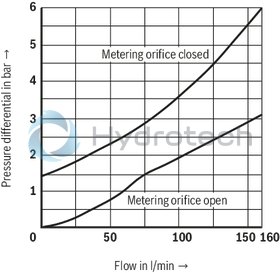
Minimum pressure differential |
bar |
3 … 8 | 6 … 10 | |
|
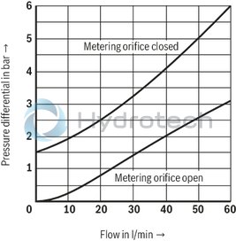
Pressure differential with free return flow B → A |
See characteristic curve | |||
|
Temperature drift |
hydraulic and electric |
% |
0.1 | |
|
pressure-compensated |
% |
± 2 | ||
|
Hydraulic fluid temperature range |
°C |
-20 … +80 | ||
|
Viscosity range |
mm²/s |
15 … 380 | ||
|
Maximum admissible degree of contamination of the hydraulic fluid, cleanliness class according to ISO 4406 (c) 1) |
Class 20/18/15 according to ISO 4406 (c) | |||
|
Hysteresis |
% |
< ± 1 | ||
|
Repetition accuracy |
% |
< 1 | ||
|
Manufacturing tolerance |
at command value 33 % |
% |
≤ ± 2 | |
|
at command value 100 % |
% |
≤ ± 5 | ||
| 1) | The cleanliness classes specified for the components must be adhered to in hydraulic systems. Effective filtration prevents faults and simultaneously increases the life cycle of the components. For the selection of the filters, see www.boschrexroth.com/filter. |
|
Hydraulic fluid |
Classification |
Suitable sealing materials |
Standards |
Data sheet |
|
Mineral oils |
HL, HLP |
FKM |
DIN 51524 |
90220 |
|
Flame-resistant - water-free |
HFDU (glycol base) |
FKM |
ISO 12922 |
90222 |
|
Important information on hydraulic fluids: For more information and data on the use of other hydraulic fluids please contact us. There may be limitations regarding the technical valve data (temperature, pressure range, life cycle, maintenance intervals, etc.). The ignition temperature of the hydraulic fluid used must be 50 K higher than the maximum surface temperature. |
||||
electrical
|
Type |
2FRE | ||
|
Voltage type |
Direct voltage | ||
|
Maximum solenoid current |
A |
1.5 | |
|
Solenoid coil resistance |
Cold value at 20 °C |
Ω |
10 |
|
Maximum hot value |
Ω |
13.9 | |
|
Duty cycle |
% |
100 | |
|
Protection class according to DIN EN 60529 |
IP65 (with mating connector mounted and locked) | ||
electrical, inductive position transducer
|
Type |
2FRE | ||
|
Coil resistance at 20°C |
Total resistance between 1 and 2 |
Ω |
31.5 |
|
Total resistance between 2 and PE |
Ω |
45.5 | |
|
Total resistance between PE and 1 |
Ω |
31.5 | |
|
Type of protection according to EN 60529 |
IP65 (with mating connector mounted and locked) | ||
|
Inductivity |
mH |
6 ... 8 | |
|
Oscillator frequency |
kHz |
2.5 | |
|
Electrical position measurement system |
Differential throttle | ||
|
Nominal stroke |
mm |
4 | |
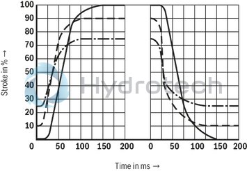
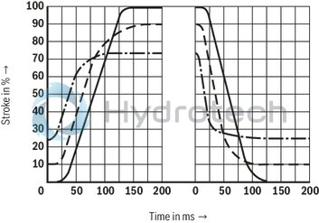
measured at ν = 41 mm2/s and ϑ = 50 °C; pnom = 50 bar; amplitude 0 → 100 %; NG10 type 60L / NG16 type 160L
Transition function with stepped electric input signals
Size 10
Transition function with stepped electric input signals
Size 16
Frequency response
NG10 and 16
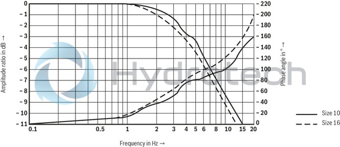
measured at ν = 41 mm2/s and ϑ = 50 °C
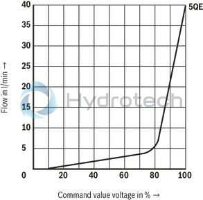
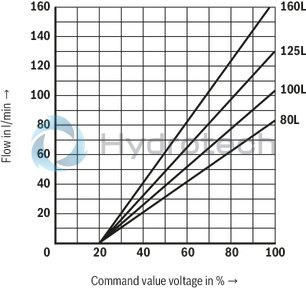
Dependency of the flow from the command value voltage (flow control from A → B)
Linear characteristic curve “L”
Size 10

Progressive
Size 10
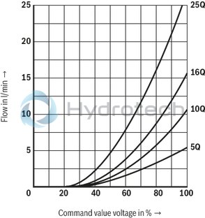
Progressive with rapid traverse
Size 10
Linear characteristic curve “L”
Size 16
Pressure differential across the check valve from B to A
Size 10
Pressure differential across the check valve from B to A
Size 16
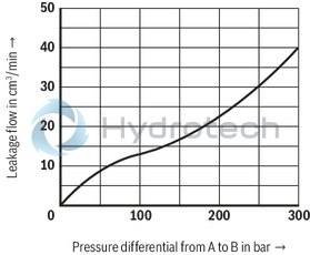
Zero flow from A → B
Size 10
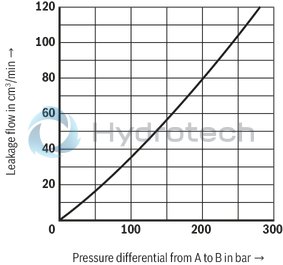
Zero flow from A → B
Size 16
|
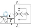
Proportional flow control valve (simplified, detailed) |
|
|
simplified |
|
|
Detailed |
Proportional flow control valve; simplified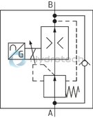
|
Rectifier sandwich plate (① = component side, ② = plate side); type Z4S ...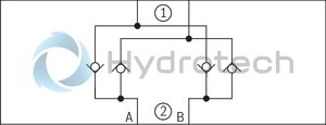
|
|
Connection at the connector

Connection at mating connector

Inductive position transducer
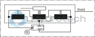
Proportional flow control valve
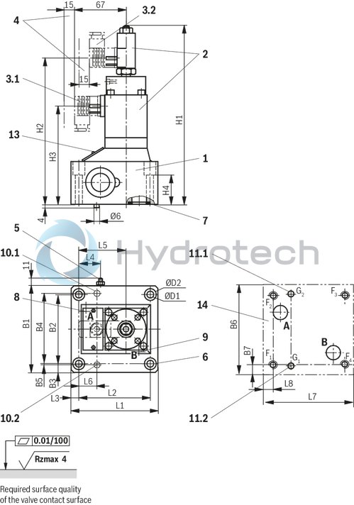
Dimensions in mm
|
NG |
10 |
16 |
|
B1 |
95 |
123,5 |
|
B2 |
76 |
101,5 |
|
B3 |
9,5 |
11 |
|
B4 |
79,4 |
102,4 |
|
B5 |
- |
0,8 |
|
B6 |
97 |
126 |
|
B7 |
10,5 |
12 |
|
ØD1 |
9 |
11 |
|
ØD2 |
15 |
18 |
|
H1 |
245 |
255,5 |
|
H2 |
200 |
210 |
|
H3 |
210 |
140 |
|
H4 |
48 |
51 |
|
L1 |
102,5 |
123,5 |
|
L2 |
82,5 |
101,5 |
|
L3 |
10 |
11 |
|
L4 |
24 |
31 |
|
L5 |
62,5 |
72,5 |
|
L6 |
23,8 |
28,6 |
|
L7 |
105 |
126 |
|
L8 |
11 |
12 |
|
1 |
Valve housing |
|
2 |
Proportional solenoid with inductive position transducer |
|
3.1 |
Mating connector for proportional solenoid, separate order |
|
3.2 |
Mating connector for inductive position transducer, separate order |
|
4 |
Space required to remove the mating connector |
|
5 |
Pressure compensator stroke limitation: Grub screw with internal hexagon SW3, lock nut SW10 |
|
6 |
Valve mounting screws (separate order) |
|
7 |
Identical seal rings for ports A and B |
|
8 |
Port A |
|
9 |
Port B |
|
10.1 |
Locking pin with NG10 and 16 |
|
10.2 |
Locking pin with NG16 |
|
11.1 |
Locating hole for locking pin with NG10 and 16 |
|
11.2 |
Locating hole for locking pin with NG16 |
|
13 |
Name plate |
|
14 |
Machined valve contact surface: |
Valve mounting screws NG10 (separate order):
without rectifier sandwich plate:
4 hexagon socket head cap screws ISO 4762 - M8 x 60 - 10.9-flZn-240h-L
Tightening torque MA = 30 Nm ± 10 % , material no. R913000217
or
4 hexagon socket head cap screws ISO 4762 - M8 x 60 - 10.9
Tightening torque MA = 34 Nm ± 10 %
with rectifier sandwich plate:
4 hexagon socket head cap screws ISO 4762 - M8 x 120 - 10.9-flZn-240h-L
Tightening torque MA = 30 Nm ± 10 % , material no. R913000423
or
4 hexagon socket head cap screws ISO 4762 - M8 x 120 - 10.9
Tightening torque MA = 34 Nm ± 10 %
Notice:
The tightening torque of the hexagon socket head cap screws refers to maximum operating pressure!
Valve mounting screws NG16 (separate order):
without rectifier sandwich plate:
4 hexagon socket head cap screws ISO 4762 - M10 x 70 - 10.9-flZn-240h-L
Tightening torque MA = 64 Nm ± 10 % , material no. R913000126
or
4 hexagon socket head cap screws ISO 4762 - M10 x 70 - 10.9
Tightening torque MA = 75 Nm ± 10 %
with rectifier sandwich plate:
4 hexagon socket head cap screws ISO 4762 - M10 x 160 - 10.9-flZn-240h-L
Tightening torque MA = 64 Nm ± 10 % , material no. R913000072
or
4 hexagon socket head cap screws ISO 4762 - M10 x 160 - 10.9
Tightening torque MA = 75 Nm ± 10 %
Notice:
The tightening torque of the hexagon socket head cap screws refers to maximum operating pressure!
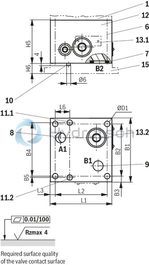
Rectifier sandwich plate
Dimensions in mm
|
NG |
10 |
16 |
|
B1 |
95 |
123,5 |
|
B2 |
76 |
101,5 |
|
B3 |
9,5 |
11 |
|
B4 |
79,4 |
102,4 |
|
B5 |
- |
0,8 |
|
ØD1 |
9 |
11 |
|
H5 |
60 |
85 |
|
H6 |
30 |
40 |
|
L1 |
102,5 |
123,5 |
|
L2 |
82,5 |
101,5 |
|
L3 |
10 |
11 |
|
L6 |
23,8 |
28,6 |
|
NG |
10 |
16 |
|
B1 |
95 |
123,5 |
|
B2 |
76 |
101,5 |
|
B3 |
9,5 |
11 |
|
B4 |
79,4 |
102,4 |
|
B5 |
- |
0,8 |
|
B6 |
97 |
126 |
|
B7 |
10,5 |
12 |
|
ØD1 |
9 |
11 |
|
ØD2 |
15 |
18 |
|
H1 |
245 |
255,5 |
|
H2 |
200 |
210 |
|
H3 |
210 |
140 |
|
H4 |
48 |
51 |
|
L1 |
102,5 |
123,5 |
|
L2 |
82,5 |
101,5 |
|
L3 |
10 |
11 |
|
L4 |
24 |
31 |
|
L5 |
62,5 |
72,5 |
|
L6 |
23,8 |
28,6 |
|
L7 |
105 |
126 |
|
L8 |
11 |
12 |
|
1 |
Valve housing |
|
6 |
Valve mounting screws (separate order) |
|
7 |
Identical seal rings for ports A and B |
|
8 |
Port A1 (A2) |
|
9 |
Port B1 (B2) |
|
10 |
Locking pin with NG10 and 16 |
|
11.1 |
Locating hole for locking pin with NG10 and 16 |
|
11.2 |
Locating hole for locking pin with NG16 |
|
12 |
Rectifier sandwich plate |
|
13.1 |
Name plate (rectifier sandwich plate NG10) |
|
13.2 |
Name plate (rectifier sandwich plate NG16) |
|
15 |
Subplate (separate order) |
Sandwich plates
Z4S 10
Sandwich plates
Z4S 10
Size 10 Maximum operating pressure 315 bar Nominal flow 60 l/minData sheet
Spare parts & repair
Sandwich plates
Z4S 16
Sandwich plates
Z4S 16
Size 16 Maximum operating pressure 315 bar Nominal flow 160 l/minData sheet
Spare parts & repair
Mating connectors for valves with connector “K4”, without circuitry, standard
3P Z4
Mating connectors for valves with connector “K4”, without circuitry, standard
3P Z4
For valves with connector “K4” according to EN 175301-803 and ISO 4400, 2-pole + PE, “large cubic connector” Mating connectors for valves with one or two solenoids (individual connection)Data sheet
Spare parts & repair