

BOSCH REXROTH
R911171949
$6,802.48 USD
- BOSCH REXROTH
- Material:R911171949
- Model:R-ILBS3AI12AO4SSI-IN4
Quantity in stock: 0
The Bosch Rexroth R-ILB S3 AI12 AO4 SSI-IN4 (R911171949) is a highly versatile I/O module that seamlessly integrates into a SERCOS III network environment. This module is specifically engineered to manage both the acquisition of analog input signals and the output of analog signals, making it an essential component for precise control in automation tasks. The R-ILB S3 AI12 AO4 SSI-IN4 boasts 12 analog input channels and 4 analog output channels, providing ample connectivity for various sensors and actuators. One of the standout features of this module is its support for absolute encoders through its SSI interfaces. These interfaces are capable of reading data from absolute encoders with an SSI interface up to \(\text{nbsp;bits}\), which suggests high-resolution position tracking critical for intricate motion control applications. The module's flexibility is further enhanced by its ability to support both gray and binary code outputs from these encoders, ensuring compatibility with a wide range of devices. The design and capabilities of the R-ILB S3 AI12 AO4 SSI-IN4 make it ideal for applications requiring precise data acquisition and control. Its integration within a SERCOS III network highlights its suitability for synchronized communication in complex automation systems, where timing and accuracy are paramount. Whether used in manufacturing, robotics, or any field that relies on exacting analog signal processing coupled with high-fidelity encoder feedback, this Bosch Rexroth I/O module stands out as a reliable solution.
This module is designed for use within a SERCOS III network. It is used to acquire analog input signals and to output analog signals. The SSI interfaces are used to read out data from absolute encoders with an SSI interface up to 31 bits. They support encoders with gray and binary code.
General data
|
Type |
R-ILB S3 AI12 AO4 SSI-IN4 | |
|
Weight 1) |
g |
505 |
|
Operating mode |
Sercos III process data operation | |
|
Sensor connection type |
2-, 3-wire technology (shielded) | |
|
Actuator connection type |
2-, 3-wire technology (shielded) | |
|
Ambient temperature (operation) |
-25 °C ... +60 °C | |
|
Ambient temperature (storage/transport) |
-25 °C ... +85 °C | |
|
Permissible relative humidity (operation) |
10 % ... 95 % acc. to DIN EN 61131-2 | |
|
Permissible relative humidity (storage/transport) |
10 % ... 95 % acc. to DIN EN 61131-2 | |
|
Air pressure (operation) |
70 kPa ... 106 kPa (up to 3000 m above sea level) | |
|
Air pressure (storage/transport) |
70 kPa ... 106 kPa (up to 3000 m above sea level) | |
|
Protection type |
IP20 | |
|
Protection class |
III, IEC 61140, EN 61140, VDE 0140-1 | |
|
Clearances and creepage distances |
Acc. to DIN VDE 0110/IEC 60664, IEC 60664A, DIN VDE 0160/EN 50178/IEC 62103 | |
|
Housing material |
Plastic, PVC-free, PBT, self-extinguishing (V0) | |
|
Degree of contamination 2) |
2; dewing in operation is not permitted! | |
|
Overvoltage class |
II | |
| 1) | Including plug |
| 2) | Acc. to EN 60664-1/IEC 60664-1, EN 61131-2/IEC 61131-2 |
Connection data
|
Type |
R-ILB S3 AI12 AO4 SSI-IN4 | |
|
Designation |
Inline connection plug | |
|
Connection type |
Tension spring modules | |
|
Conductor cross-section solid/flexible/AWG |
0.08 mm² ... 1.5 mm² 0.08 mm² ... 1.5 mm² 28 ... 16 |
|
|
Permissible cable length |
m |
30 |
Interface fieldbus
|
Type |
R-ILB S3 AI12 AO4 SSI-IN4 | |
|
Number of interfaces |
2 | |
|
Connection type |
RJ45 plug; shielding via parallel connection of R, C, and VDR | |
|
Connectivity technology |
Sercos III | |
|
Transmission speed |
100 MBit/s | |
SSI interface
|
Type |
R-ILB S3 AI12 AO4 SSI-IN4 | |
|
Absolute encoder inputs |
||
|
Number |
4 | |
|
Connection type |
Shielded line | |
|
Encoder signals |
Clock, clock inverted (acc. to RS-422 protocol); data, data inverted (acc. to RS-422 protocol) | |
|
Encoder |
||
|
Resolution |
8 ... 31 Bit | |
|
Encoding |
Gray or binary code (configurable) | |
|
Parity control |
None, even, uneven (configurable) | |
|
Transmission frequency 1) |
kHz kHz kHz kHz kHz kHz kHz kHz kHz kHz kHz kHz kHz MHz MHz MHz |
67.5 100 125 200 250 100 300 400 500 600 700 800 900 1 2 4 |
|
Encoder supply |
||
|
Nominal voltage |
24 V DC | |
|
Voltage range |
19.2 V DC ... 30 V DC | |
|
Current-carrying capacity |
mA |
≤ 200 |
|
Short-circuit protection |
Thermal (self healing) | |
|
Line length 2) |
m |
< 30 |
| 1) | Configurable |
| 2) | With shielded line (to ensure compliance with the EMC directive 89/336/EEC) |
24 V module supply (logic and sensor supply)
|
Type |
R-ILB S3 AI12 AO4 SSI-IN4 | ||
|
Rated value |
V DC |
24 | |
|
Tolerance |
-15 %/+20 % acc. to EN 61131-2 | ||
|
Ripple 1) |
% |
± 5 | |
|
Permissible range |
19.2 ... 30 V DC | ||
|
Current consumption from UL |
See "Current consumption from UL and US" | ||
|
Current consumption from US |
See "Current consumption from UL and US" | ||
|
Protection measures |
For UL |
Transient overload protection via diverter, serial reverse polarity protection | |
|
For US |
Transient overload protection via diverter, serial reverse polarity protection, short-circuit protection by channel with single-channel diagnostics | ||
|
Connection |
Via power supply plug | ||
| 1) | Acc. to EN 61131-2 |
Electronically-protected initiator supply UIS (via feed from US)
|
Type |
R-ILB S3 AI12 AO4 SSI-IN4 | |
|
Nominal value UIS |
24 V DC | |
|
Nominal current IIS per channel |
mA |
200 |
|
Guarantee |
Internal, channel electronic fuse, short-circuit protected with single-channel diagnostics - - - |
|
Analog inputs
|
Type |
R-ILB S3 AI12 AO4 SSI-IN4 | |
|
Number of analog inputs 1) |
12 | |
|
Data formats |
IB IL | |
|
Measurement representation |
16 bits (15 bits + sign) - - - - - |
|
|
Input filter |
10 kHz HW filter, average value formation via software filters with adjustable value number software | |
|
Conversion time for the A/D converter |
µs |
75 |
|
Cut-off frequency (–3 dB) of the input filter |
kHz |
10 |
|
Transient protection |
Via diverter | |
|
Signal connection type |
2-, 3-wire technology, shielded cable, twisted pair | |
|
Overload protection |
Yes, minimum ±30 V DC | |
| 1) | Analog differential inputs |
Analog differential voltage inputs
|
Type |
R-ILB S3 AI12 AO4 SSI-IN4 | |
|
Input range |
0 V … 10 V; ± 10 V - - - |
|
|
Input resistance |
kΩ |
≥ 260 |
|
Open circiut response |
Goes to 0 V | |
|
Maximum permissible voltage between analog voltage inputs and analog mass (UCM) |
V DC |
± 30 |
Analog differential current inputs
|
Type |
R-ILB S3 AI12 AO4 SSI-IN4 | |
|
Input range |
±10 mA; 0 mA … 20 mA 4 mA … 20 mA; ± 20 mA - |
|
|
Input resistance |
Ω |
240 |
|
Open circiut response |
Goes to 0 mA | |
|
Maximum permissible current per current input |
Electronically overload protected | |
|
Overload protection at the analog current inputs |
Yes, minimum ±30 V DC | |
Analog outputs
|
Type |
R-ILB S3 AI12 AO4 SSI-IN4 | ||
|
Number of analog outputs |
4 | ||
|
Signal connection type |
2-, 3-wire technology, shielded cable, twisted pair | ||
|
Output voltage range |
0 ... 10 V, ±10 V | ||
|
Output current range |
0 ... 20 mA, ±20 mA, 4 ... 20 mA | ||
|
Data formats |
IB IL | ||
|
Measurement representation |
16 bits (15 bits + sign) - - - - - |
||
|
Conversion time of the D/A converter |
µs |
75 | |
|
Resolution of the D/A converters |
bits |
16 | |
|
Output load |
Voltage output RLmin |
kΩ |
2 |
|
Current output RLB |
0 Ω ... 500 Ω | ||
|
Transient protection |
Via diverter | ||
|
Short-circuit protection |
Voltage output |
Permanently electronically short-circuit protected | |
|
Current output |
Permanently electronically short-circuit protected | ||
|
Free switching function |
Internal electronic | ||
|
Optical displays |
5 % output LED, by channel | ||
Electrical isolation/insulation of the voltage ranges
|
Type |
R-ILB S3 AI12 AO4 SSI-IN4 | |
|
Test distance |
Test voltage | |
|
Sercos III/logic |
500 V AC, 50 Hz, 1 min. | |
|
Sercos III / analog peripherals |
500 V AC, 50 Hz, 1 min. | |
|
Sercos III/logic supply UL |
500 V AC, 50 Hz, 1 min. | |
|
Sercos III/initiator supply US |
500 V AC, 50 Hz, 1 min. | |
|
Sercos III/function earth |
500 V AC, 50 Hz, 1 min. | |
|
SSI (7.5 V supply (bus logic))/peripherals |
500 V AC, 50 Hz, 1 min. | |
|
SSI (7.5 V supply (bus logic))/function earth |
500 V AC, 50 Hz, 1 min. | |
|
SSI (24 V supply (peripherals))/function earth |
500 V AC, 50 Hz, 1 min. | |
|
Logic / analog peripherals |
500 V AC, 50 Hz, 1 min. | |
|
Logic/logic supply UL |
500 V AC, 50 Hz, 1 min. | |
|
Logic/initiator supply US |
500 V AC, 50 Hz, 1 min. | |
|
Logic/function earth |
500 V AC, 50 Hz, 1 min. | |
|
Analog peripherals/logic supply UL |
500 V AC, 50 Hz, 1 min. | |
|
Analog peripherals/initiator supply US |
500 V AC, 50 Hz, 1 min. | |
|
Analog peripherals/function earth |
500 V AC, 50 Hz, 1 min. | |
|
Logic supply UL/initiator supply US |
500 V AC, 50 Hz, 1 min. | |
|
Logic supply UL/function earth |
500 V AC, 50 Hz, 1 min. | |
|
Initiator supply US/function earth |
500 V AC, 50 Hz, 1 min. | |
Current consumption from UL and US
| Typical | Maximum | |||
|
Current consumption from UL |
No load of outputs and AI operation |
mA |
180 | 200 |
|
AO-U nominal load (UOUT = 10 V with RL = 2 kΩ) |
mA |
208 | 225 | |
|
AO-I nominal load (IOUT = 20 mA with RL = 0 Ω) |
mA |
255 | 270 | |
|
Current consumption from US |
No load SSI without encoder and encoder power supply |
mA |
38 | 40 |
|
SSI with 4 encoders MBaud without encoder power supply |
mA |
70 | 80 | |
|
SSI with 4 encoders MBaud with encoder power supply (4 x 200 mA) |
mA |
890 | 900 | |
|
Total current consumption from UL and US |
No load of outputs and AI operation |
mA |
220 | 240 |
|
AO-U nominal load/SSI nominal load (UOUT = 10 V with RL = 2 kΩ); 4 x SSI encoder 1 MBaud without encoder power supply |
mA |
278 | 305 | |
|
AO-U nominal load/SSI nominal load (IOUT = 20 mA with RL = 0 Ω); 4 x SSI encoder 1 MBaud without encoder power supply |
mA |
325 | 350 | |
|
AO-U nominal load/SSI nominal load (IOUT = 20 mA with RL = 0 Ω); 4 x SSI encoder 1 MBaud with encoder power supply (4 x 200 mA) |
mA |
1125 | 1150 | |
Tolerances at TU = 25 °C
| Absolute, typical | Absolute, maximum | Relative, typical | Relative, maximum | |||
|
Measurement range AI |
0 V ... 10 V ±10 V |
± 20 mV | ± 30 mV | 0.2 % | ± 0.3 % | |
|
0 mA ... 20 mA ±10 mA |
± 40 μA | ± 60 μA | 0.2 % | ± 0.3 % | ||
|
4 mA ... 20 mA ±20 mA |
± 40 μA | ± 60 μA | 0.2 % | ± 0.3 % | ||
|
Output range AO |
0 V ... 10 V ±10 V |
± 10 mV | ± 15 mV | 0.1 % | ± 0.2 % | |
|
0 mA ... 20 mA ±10 mA |
± 20 μA | ± 40 μA | 0.1 % | ± 0.2 % | ||
|
4 mA ... 20 mA ±20 mA |
± 20 μA | ± 40 μA | 0.1 % | ± 0.2 % | ||
Tolerance and temperature behavior at TU = -25 °C ... +60 °C
| Drift, typical | Drift, maximum | |||
|
Measurement range AI |
0 V ... 10 V ±10 V |
ppm/K |
± 50 | ± 65 |
|
0 mA ... 20 mA ±10 mA |
ppm/K |
± 60 | ± 75 | |
|
4 mA ... 20 mA ±20 mA |
ppm/K |
± 60 | ± 75 | |
|
Output range AO |
0 V ... 10 V ±10 V |
ppm/K |
± 23 | ± 30 |
|
0 mA ... 20 mA ±10 mA |
ppm/K |
± 23 | ± 30 | |
|
4 mA ... 20 mA ±20 mA |
ppm/K |
± 23 | ± 30 | |
|
Formula for calculating the tolerance under temperature influence |
||
|
Typical temperature drift |
Drifttyp = Δθ x TCtyp x MREV |
|
|
where: |
||
|
Drifttyp |
Typical temperature drift |
|
|
Δθ |
Temperature difference between the ambient temperature of module Ta and +25 °C |
|
|
TCtyp |
Temperature coefficient typically in ppm/C |
|
|
MREV |
Measurement range end value (e.g. 10 V voltage mode) |
|
|
Maximum temperature drift |
Driftmax = Δθ x TCmax x MREV |
|
|
where: |
||
|
Driftmax |
Maximum temperature drift |
|
|
Δθ |
Temperature difference between the ambient temperature of module Ta and +25 °C |
|
|
TCmax |
Temperature coefficient maximum in ppm/C |
|
|
MREV |
Measurement range end value |
|
|
Example |
Voltage mode 10 V |
|
Tolerances under the influence of electromagnetic interference
|
Analog input power |
Analog input voltage |
Analog output power |
Analog output voltage |
|||
|
Electro-magnetic fields |
Acc. to EN 61000-4-3/IEC 61000-4-3 |
% |
< ± 1.5 | < ± 5 | < ± 0.5 | < ± 0.5 |
|
Fast transients (burst) |
Acc. to EN 61000-4-4/IEC 61000-4-4 |
% |
- | 5 | - | - |
|
Line-fed disturbances |
Acc. to EN 61000-4-6/IEC 61000-4-6 |
- | - | - | - | |
Signal rise times
| 10 % ... 90 % | 0 % ... > 99 % | ||
|
Voltage output 0 V ... 10 V (typical data) |
|||
|
Ohmic load RL = 2 kΩ |
µs |
15 | 30 |
|
Ohmic/capacitive load RL = 2 kΩ/CL = 10 nF |
µs |
15 | 20 |
|
Ohmic/capacitive load RL = 2 kΩ/CL = 220 nF |
µs |
150 | 230 |
|
Ohmic/inductive load RL = 2 kΩ/LL = 3.3 mH |
µs |
15 | 30 |
|
Power output 0 mA ... 20 mA (typical data) |
|||
|
Ohmic load RL = 500 Ω |
µs |
4 | 10 |
|
Ohmic/capacitive load RL = 500 Ω/CL = 10 nF |
µs |
15 | 30 |
|
Ohmic/capacitive load RL = 500 Ω/CL = 220 nF |
µs |
350 | 600 |
|
Ohmic/inductive load RL = 500 Ω/LL = 3.3 mH |
µs |
2 | 400 |
|
Power output 4 mA ... 20 mA (typical data) |
|||
|
Ohmic load RL = 500 Ω |
µs |
4 | 10 |
|
Ohmic/capacitive load RL = 500 Ω/CL = 10 nF |
µs |
15 | 30 |
|
Ohmic/capacitive load RL = 500 Ω/CL = 220 nF |
µs |
300 | 500 |
|
Ohmic/inductive load RL = 500 Ω/LL = 3.3 mH |
µs |
3 | 350 |
Mechanical tests
|
Type |
R-ILB S3 AI12 AO4 SSI-IN4 | |
|
Vibration resistance 1) |
Load 5 g, 2.5 h per spatial direction | |
|
Shock 2) |
Load 30 g for 11 ms, half sinusoidal wave, three shocks per spatial direction and orientation | |
|
Broadband noise 3) |
Load 0.78 g, 2.5 h per spatial direction | |
| 1) | Acc. to EN 60068-2-6/IEC 60068-2-6 |
| 2) | Acc. to EN 60068-2-27/IEC 60068-2-27 |
| 3) | Acc. to EN 60068-2-64/IEC 60068-2-64 |
Conformity
|
Type |
R-ILB S3 AI12 AO4 SSI-IN4 | ||
|
Conforms with |
|||
|
Testing of interference immunity acc. to EN 61000-6-2 |
Discharge of static electricity (ESD) |
Criterion B; 4 kV contact discharge; 8 kV air discharge acc. to EN 61000-4-2/IEC 61000-4-2 | |
|
Electro-magnetic fields |
Criterion A; field strength: 10 V/m acc. to EN 61000-4-3/IEC 61000-4-3 | ||
|
Fast transients (burst) |
Criterion B; remote bus: 2 kV; voltage supply: 2 kV; I/O lines: 2 kV; criterion A; all interfaces: 1 kV acc. to EN 61000-4-4/IEC 61000-4-4 | ||
|
Transient overvoltage (surge) |
Criterion B; supply lines DC: ±0.5 kV/±0.5 kV (symmetric/asymmetric); signal lines: ±1 kV/±1 kV (symmetric/asymmetric) acc. to EN 61000-4-5/IEC 61000-4-5 | ||
|
Line-fed disturbances |
Criterion A; test voltage 10 V acc. to EN 61000-4-6/IEC 61000-4-6 | ||
|
Testing of disturbance transmission acc. to EN 61000-6-4 |
Testing of line-fed disturbance transmission |
Class A acc. to EN 55011 | |
|
Approvals |
|
The current approvals can be found at www.boschrexroth.com. |
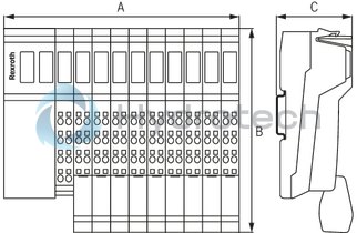
Dimensions
|
Type |
R-ILB S3 AI12 AO4 SSI-IN4 | |
|
A |
mm |
156 |
|
B |
mm |
141 |
|
C |
mm |
57 |
|
Note on dimensions |
The depth applies when using a support rail TH 35-7.5 (acc. to EN 60715). | |