

BOSCH REXROTH
R978916539
$1,106.78 USD
- BOSCH REXROTH
- Material:R978916539
- Model:VT-VSPA1-1-1X/ES43A8-3564/A2,A3
Quantity in stock: 0
The Bosch Rexroth VT-VSPA1-1-1X/ES43A8-3564/A2A3 (R978916539) is an advanced electronic amplifier card designed to control proportional valves with precision. This component, part of series X in the Eurocard format, is compatible with a range of Bosch Rexroth valves including DBEP AB ...X, DBEM ...X series, ZDBE ...X, DREM ...X series, and ZDRE VP ...X. The unit features a differential input that can be switched from voltage to current input, accommodating a variety of signal types. The VT-VSPA1-1-1X/ES43A8-3564/A2A3 offers a ramp generator with separately adjustable upward and downward directions, ensuring smooth transitions and preventing system shocks during operation changes. Cable break detection for the current input ranging from 0 to 20 mA or 4 to 20 mA ensures the integrity of connections and operational reliability. Equipped with reverse polarity protection for the operating voltage, this unit also includes short-circuit protection and cable break detection for solenoid conductors. An internal command value presetting along with an external command value potentiometer option allows for flexible configuration based on specific application requirements. For signaling operational status, this model provides a ready-for-operation message through an illuminated LED indicator when there are no shorts or overloads detected and when a valid command value is present. In case of a fault condition such as short circuit or cable break in the solenoid conductor, the device ensures quick diagnosis through its comprehensive monitoring capabilities. This amplifier card's clocked power output stage delivers consistent power to the valve solenoid while allowing modulation with a dither signal to prevent sticking and ensure smooth operation. With its robust design and versatile features, the Bosch Rexroth VT-VSPA1-1-1X/ES43A8-3564/A2A3 amplifier card is an essential component for precise control in hydraulic systems.
[ ] … Assignment to the block diagram
The ramp generator [4] output signal is forwarded to the summing amplifier [5] as current command value. Here, a voltage of +6 V corresponds to a command value of 100 %.
In the summing amplifier [5], the output signals of the characteristic curve generators [6 or 7] are added to the command value (can be selected by means of DIL switches depending on the valve to be controlled). The current command value can be filtered by means of a connectible low pass. The current output stage [9] is controlled using the current controller [8]. In the current controller, the current command value is moreover modulated with the clock generator signal [10] (frequency can be programmed using the DIL switch). In the valve solenoid, the clocked actual current value acts like a constant current with superimposed dither signal. Type VT-VSPA1-1 has measuring sockets for the internal command value and the actual value.
The following is true for the command value:+6 V ≙ 100 %
The following is true for the actual value: 1 mV ≙ 1 mA
The “ready for operation” signal is output and the “H2” LED on the front plate (with VSPA1-1) or the “H2” LED (with VSPA1K-1) is illuminated if:
there is no short-circuit of the solenoid conductors and no overload of the output stage,
a command value is available (cable break detection),
there is no cable break of the solenoid conductor.
In case of a fault, the following applies:
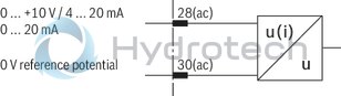
The command value input 2 is a differential input [1] (0 to +10 V). By means of DIL switches , it can be configured as current input (4 to 20 mA or 0 to 20 mA). If the command value is specified by external electronics with a different reference potential (e. g. by a PLC), this input has to be used. When disconnecting or connecting the command value voltage, it has to be ensured that both signal lines are in each case separated from or connected with the input.
Before they are forwarded, both command values are summed up [2] and then reach a potentiometer [3] accessible at the front plate of the card which acts as attenuator and thus limits the maximum command value.
The downstream ramp generator [4] generates a ramp-shaped output signal from a given stepped input signal. The time constant of this signal can be separately adjusted for the upwards and downwards direction by means of two potentiometers. The specified ramp time refers to a command value step of 100 % and may be approx. 1 s or 5 s, depending on the setting by means of a DIL switch. If a command value step of less than 100 % is switched to the ramp generator input or if the attenuator [3] is effective, the ramp time will be correspondingly shorter.
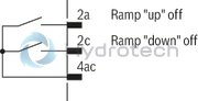
To type VT-VSPA1-1, the following applies: By means of the external “Ramp Up/Down off” contacts, the upwards and downwards ramp times can be separately set to their minimum value (approx. 30 ms).
To type VT-VSPA1K-1, the following applies: By means of the external “Ramp off” contact, the upwards and downwards ramp times can be set to their minimum value (approx. 30 ms) together.
Notice:
If an external command value potentiometer is used, the internal potentiometer “Gw” [3] must be set to maximum or to the desired maximum pressure.
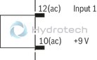
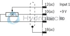
The command value voltage is specified at the command value input 1 either directly or via an external command value potentiometer by means of the regulated voltage +9 V of the power supply unit [14]. The reference potential for command value 1 is M0 (measurement zero). To this input, the following applies: +9 V ≙ +100 %.
Differential input (input 2)
Internal command value presetting
External command value presetting
Ramp “up/down” off
VT-VSPA1-1
Ramp off
VT-VSPA1K-1
|
Outlet |
LED |
|
|
Short-circuit |
low |
off |
|
Cable break |
clocked |
flashing |
|
01 |
02 |
03 |
04 |
05 |
|||
|
VT-VSPA1 |
‒ |
1 |
‒ |
1X |
/ |
* |
|
01 |
Valve amplifier for proportional pressure valves, analog, euro-card format |
VT-VSPA1 |
|
02 |
With 32-pole male multipoint connector and front plate |
No code |
|
With 16-pole terminal strip, without front plate |
K |
|
|
03 |
For valves: |
1 |
|
04 |
Component series 10 ... 19 (10 ... 19: unchanged installation and connection dimensions) |
1X |
|
05 |
Further details in the plain text |
* |
When replacing amplifiers VT 2000 (up to component series 4x) VT 2010, VT 2013 or VT 2023, the blind plate 4TE/3HE, material no. R900021004, must be ordered separately for the rack mounting.
General
|
Type / version |
VT-VSPA1K-1-1X | VT-VSPA1-1-1X | ||
|
Type of electronics |
Analog | |||
|
Design |
Euro-card | |||
Voltage supply
|
Type / version |
VT-VSPA1K-1-1X | VT-VSPA1-1-1X | |||
|
Operating voltage |
nominal |
U |
V |
24 | |
|
Lower limit value |
UB(t)min |
V |
22 | ||
|
Upper limit value |
UB(t)max |
V |
35 | ||
|
Power consumption |
max. |
Smax |
VA |
50 | |
|
Current consumption |
max. |
Imax |
A |
1.8 | |
|
Fuse |
2.5 A time-lag | ||||
Analog inputs
|
Type / version |
VT-VSPA1K-1-1X | VT-VSPA1-1-1X | ||||
|
Command value |
Voltage (differential input) |
U |
V |
0 ... 10 | ||
|
Voltage (differential input) |
Input resistance |
R |
kΩ |
≥ 100 | ||
|
Voltage |
grounded on one side, first input |
Ucommand |
V |
0 … 9 | ||
|
Current |
I |
mA |
4 … 20 | |||
|
Current |
Input resistance |
R |
Ω |
100 | ||
|
Current |
I |
mA |
0 … 20 | |||
|
Current |
Input resistance |
R |
Ω |
100 | ||
Digital inputs
|
Type / version |
VT-VSPA1K-1-1X | VT-VSPA1-1-1X |
Analog outputs
|
Type / version |
VT-VSPA1K-1-1X | VT-VSPA1-1-1X | |||
|
Internal command value |
U |
V |
0 ... 6 | ||
|
Actual current value |
U |
V |
0 ... 1.6 (mV ≙ mA) | ||
Digital outputs
|
Type / version |
VT-VSPA1K-1-1X | VT-VSPA1-1-1X | |||
|
Ready for operation |
On (active) |
U |
V |
UB 1) | |
|
Ready for operation |
Off (inactive) |
U |
V |
0 |
| 1) | Imax = 50 mA, Ri = 10 kΩ |
Solenoid outputs
|
Type / version |
VT-VSPA1K-1-1X | VT-VSPA1-1-1X | ||||
|
Solenoid current |
max. |
Imax |
A |
0.8 | ||
|
Coil resistance at 20°C |
R(20) |
Ω |
19.5 | |||
|
Solenoid current |
max. |
alternatively |
Imax |
A |
1.6 | |
|
Coil resistance at 20°C |
alternatively |
R(20) |
Ω |
5.4 | ||
|
Clock frequency |
Setting range |
stepped |
f |
Hz |
100, 200, 300, 370, ±10% in each case | |
Adjustment options
|
Type / version |
VT-VSPA1K-1-1X | VT-VSPA1-1-1X | ||||
|
Pilot current |
with Imax = 0.8 A |
I |
mA |
Adjustable: 50 or 100 mA | ||
|
with Imax = 1.6 A |
I |
mA |
100 | |||
|
Setting range |
with Imax = 0.8 A |
I |
mA |
0 ... 300 ±20 % | ||
|
with Imax = 1.6 A |
I |
mA |
0 ... 600 ±20 % | |||
|
Ramp time up/down |
Ramp 1 |
t |
s |
0.03 … 1 | ||
|
Ramp 2 |
t |
s |
0.03 … 5 | |||
Measuring sockets
|
Type / version |
VT-VSPA1K-1-1X | VT-VSPA1-1-1X | |||
|
Command value 1) |
"w" |
Uw |
V |
0 ... 6 | |
|
Actual value |
I |
i |
A |
0 ... 1.6 (mV ≙ mA) | |
| 1) | 6 V ≙ 100 %, Ri = 1 kΩ |
Displays
|
Type / version |
VT-VSPA1K-1-1X | VT-VSPA1-1-1X | ||
|
LED display |
Green 1 |
Ready for operation |
Other information
|
Type / version |
VT-VSPA1K-1-1X | VT-VSPA1-1-1X | |||
|
Reference voltage |
Potentiometer supply |
U |
V |
±9 ±1% (Imax = 25 mA) | |
|
Anschlussart |
16-pole terminal strip | 32-pole male multipoint connector, DIN 41612, design D | |||
|
Ambient temperature range |
ϑ |
°C |
0 … 50 | ||
|
Storage temperature range |
ϑ |
°C |
-25 … 85 | ||
|
Weight |
m |
kg |
0.1 | ||
For applications outside these parameters, please consult us!
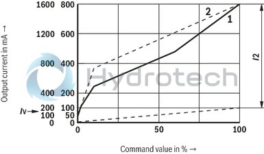
Output characteristic curve with fixedly set characteristic
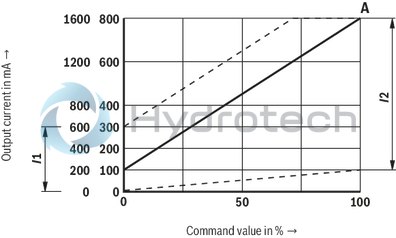
Linear output characteristic curve (basic characteristic curve)
Iv Pilot current characteristic curve 2 (qualitative representation)
I2 Setting range of the maximum command value with potentiometer “Gw”
1 Characteristic curve 1 (qualitative representation)
2 Characteristic curve 2 (qualitative representation)
I1 Pilot current setting range with potentiometer “Zw (R130)” on the printed circuit board
I2 Setting range of the maximum current with potentiometer “Gw” on the front plate
A Characteristic curve in the condition as supplied
Notice:
It has to be ensured before commissioning of the amplifiers that the DIL switches on the printed circuit board are set according to the relevant application.
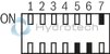
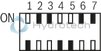
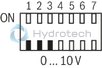
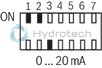
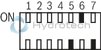
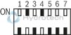
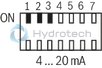
Settings independent of the valve type (command value 2 and ramp time)
|
Command value 2 |
|||
|
0 ... +10 V |
0 ... 20 mA |
4 ... 20 mA |
|
|
S11 (BR11) |
OFF |
ON |
ON |
|
S12 (BR12) |
OFF |
ON |
ON |
|
S13 (BR13) |
OFF |
OFF |
ON |
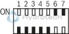
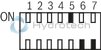
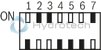
|
Maximum ramp time |
|||
|
1 s |
5 s |
||
|
S14 (BR14) |
OFF |
ON |
|
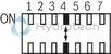
Meaning of the settings based on valve types or earlier VT20XX amplifier cards
|
DIL switch/ |
Valve types/amplifier cards |
|||
|
DBE(M)T, DBE(M)30, Pumps |
DRE(M)10-5X, |
DBE(M)10-5X, |
DRE6, |
|
|
Characteristic curves |
||||
|
Basic characteristic curve |
Characteristic curve 1 |
Characteristic curve 1 |
Characteristic curve 2 |
|
|
OFF |
ON |
ON |
OFF |
|
|
OFF |
OFF |
OFF |
ON |
|
|
Command value filter |
||||
|
f-3dB = 4 Hz |
f-3dB = 4 Hz |
f-3dB = 2.5 Hz |
||
|
OFF |
ON |
ON |
OFF |
|
|
OFF |
OFF |
OFF |
ON |
|
|
maximum solenoid current 2) |
||||
|
800 mA |
800 mA |
1600 mA |
1600 mA |
|
|
ON |
ON |
OFF |
OFF |
|
|
Clock frequency 3) |
||||
|
200 Hz |
200 Hz |
300 Hz |
370 Hz |
|
|
OFF |
OFF |
OFF |
OFF |
|
|
ON |
ON |
OFF |
OFF |
|
|
ON |
ON |
ON |
OFF |
|
|
Pilot current basic setting |
||||
|
100 mA |
50 mA |
100 mA |
100 mA |
|
|
Upon operation of switch BR22, the pilot current is increased by 50 or 100 mA. |
||||
|
1) up to component series 5X 2) Any doubling of the maximum output current will double the setting range and the set pilot current. 3) For f = 100 Hz, the DIL switches S25, S26 and S27 must be brought into “ON” position. |
||||
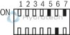
Assignment of the DIL switch settings on the card to the valve types (see also sign on the printed circuit board)
|
Valve types |
S15...S17 |
S21...S27 |
Setting for all valve types |
S11...S14 |
|
DBE(M)T, DBE(M)30, Pumps |
|
|
Ramp time |
|
|
DRE(M)10-5X, |
|
2) |
Command value 2 |
|
|
DBE(M)10-5X, |
|
2) |
|
|
|
DRE6, |
|
2) |
|
|
|
1) up to component series 5X 2) With type VT-VSPA1-1 (component series 10), the BR22 switch must be set to “ON” and the “R130” potentiometer must be rotated to the left stop in order to set the correct characteristic curve.With type VT-VSPA1-1 (from component series 11) and type VT-VSPA1K-1, switches S21 and S22 do not have any effect. The “Zw” potentiometer does not have to be operated.
|
||||
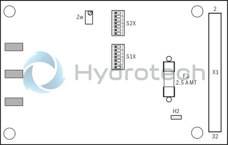
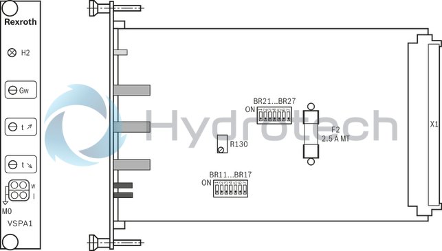
DIL switch
|
BR11...BR17 |
DIL switch |
|
BR21...BR27 |
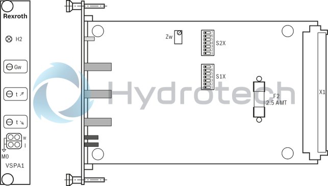
DIL switch |
|
S1X |
DIL switch |
|
S2X |
DIL switch |
Potentiometer
|
Gw |
Amplitude attenuator |
|
t ↗ |
Ramp time "Ramp up" |
|
t ↘ |
Ramp time "Ramp down" |
|
Zw, R130 |
Pilot current |
Measuring sockets
|
w |
Command value |
|
I |
Actual current value (mV ≙ mA) |
LED displays
|
H2 |
Ready for operation (green) |
VT-VSPA1-10-1X
VT-VSPA1-11-1X
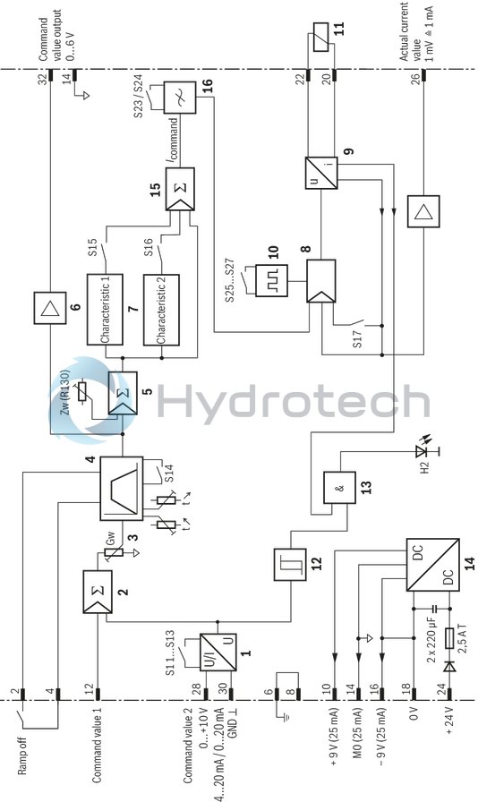
Measurement zero (M0) is increased by 9 V as compared to the 0 V operating voltage
|
1 |
Differential input |
|
2; 5; 15 |
Summing device |
|
3 |
Amplitude attenuator |
|
4 |
Ramp generator |
|
6; 7 |
Characteristic curve generator |
|
8 |
Current controller |
|
9 |
Power output stage |
|
10 |
Clock generator |
|
11 |
Proportional solenoid |
|
12 |
Command value monitoring |
|
13 |
Monitoring systems |
|
14 |
Power supply unit |
|
16 |
Low pass filter |
|
H2 |
“Ready for operation” display |
|
Gw |
Amplitude attenuator |
|
t |
Ramp time setting |
|
Zw |
Additional pilot current settings |
|
S1X, S2X |
See Operating and display elements |
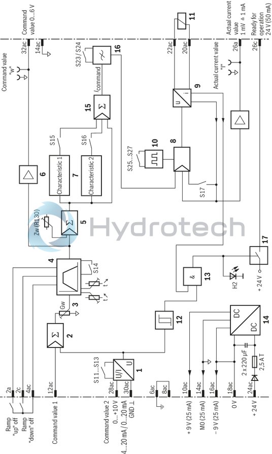
|
1 |
Differential input |
|
2; 5; 15 |
Summing device |
|
3 |
Amplitude attenuator |
|
4 |
Ramp generator |
|
6; 7 |
Characteristic curve generator |
|
8 |
Current controller |
|
9 |
Power output stage |
|
10 |
Clock generator |
|
11 |
Proportional solenoid |
|
12 |
Command value monitoring |
|
13 |
Monitoring systems |
|
14 |
Power supply unit |
|
16 |
Low pass filter |
|
17 |
"Ready for operation" output |
|
H2 |
“Ready for operation” display |
|
Gw |
Amplitude attenuator |
|
t |
Ramp time setting |
|
Zw |
Additional pilot current settings |
|
S1X, S2X |
See Operating and display elements |
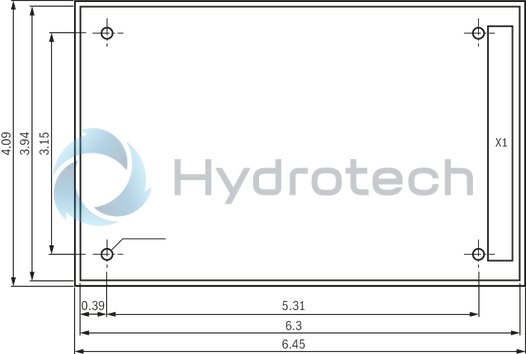
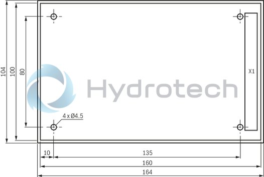
Type M-3SE 6.6X/420LG..NXDZ2/V
Dimensions in mm
Dimensions in mm
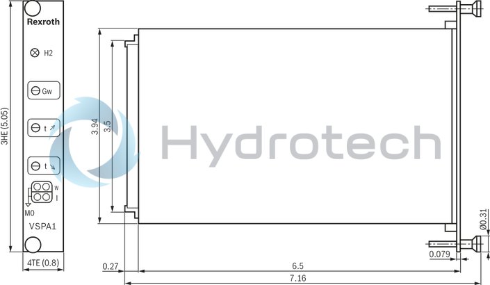
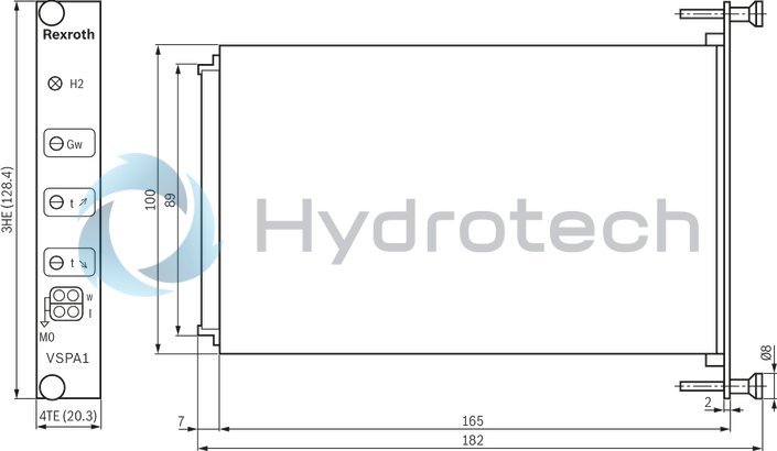
Type M-.SH…
Dimensions in mm
Dimensions in mm
It has to be ensured before commissioning of the amplifiers that the DIL switches on the printed circuit board are set according to the relevant application.
In the condition as supplied, the parameters are set as follows:
max. ramp time = 5 s, pilot current = 100 mA, max. output current = 800 mA, clock frequency = 200 Hz.
The amplifier card may only be assembled when de-energized.
No connectors with free-wheeling diodes or LED displays must be used for solenoid connection.
Only carry out measurements at the card using instruments Ri > 100 kΩ.
Measurement zero (M0) is increased by +9 V compared to 0 V operating voltage and not isolated, i.e. –9 V regulated voltage 0 V operating voltage. Thus, do not connect measurement zero (M0) to 0 V operating voltage.
For switching command values, relays with gold-plated contacts have to be used (low voltages, low currents).
Always shield command value lines, connect shielding to earth on the card-side, other side open. The card has to be connected to the earth via terminal 6 or 8. If no system earth exists, connect 0 V operating voltage.
Recommendation:
Also shield the solenoid conductors. For solenoid conductors up to 50 m in length, use the line type LiYCY 1.5 mm2. For greater lengths, please contact us.
The distance to aerial lines, radios, and radar systems has to be at least 1 m.
Do not lay solenoid conductors and signal lines near power lines.
The charging power of the smoothing capacitor on the card requires the pre-fuses to be of a slow-blowing characteristic.
If the differential input is used, both inputs must always be connected or disconnected simultaneously.
Troubleshooting
If the amplifier cards do not function, the following steps are required for troubleshooting:
Operating voltage available?
Measurement of contacts 24(ac) against 18(ac)
Fuse on card faulty?
Internal ±9 V operating voltage available on the card?
If the internal command value potentiometers are used, is the bridge from 10(ac) to 12(ac) available?
Is the external potentiometer correctly connected?
Is the differential input connected correctly?
Check:reference potential at 30(ac), 0 to +10 V at 28(ac)
Is the solenoid correctly connected?
If the card is removed, a resistance of approx. 20 Ω to 30 Ω or 5 Ω to 8 Ω has to be measurable between contacts 22(ac) and 20(ac) depending on the valve type.
The amendment of the connection designations in brackets only applies to type VT-VSPA1-1.
Notice:
The output stage switches off at overtemperature (e. g. due to overload). This error is displayed by the “H2” LED going out.
In case of cable break of input "4 to 20 mA”, the “ready for operation” signal is reset and the “H2” LED will go out as well.
From component series 11, the following applies:
In case of short-circuit or cable break of the solenoid conductor, the ready for operation output will clock and the “H2” LED will flash with a frequency of 0.5 to 2 Hz as soon as the command value is simultaneously > 2 %.