
BOSCH REXROTH
R901439036
All Other Products
BOSCH REXROTH
MATERIAL: R901439036
SUMMARY:
Quantity in stock: 0
General
The amplifier modules are intended for assembly on top hat rails. The electrical connection is established via 3 tension spring plug-in connectors. The supply voltage is 24V DC.
Power supply unit [1]
The internal power supply unit has a making current limiter to prevent current peaks. Additionally, inverse-polarity protection is integrated.
Command value, command value summing device [3]
The “internal command value” comprises:
the “external command value”, connected at the input of the differential amplifier [2] the zero point offset [4]“Z/B” in the standard – setup adjustableFor pressure valves, a positive command value results in a pressure increase at the valve.
For valves 4W..., the following applies:
Via solenoid B, a command value of 0 ... +10 V or 12 ... 20 mA results in a flow in the valve from P to A and from B to T.
Via solenoid A, a command value of 0 ... -10 V or 12 ... 4 mA results in a flow in the valve from P to B and from A to T. In the expert set-up, inversion of the command value is possible [5] (see RE 30232-B).
In normal operation, the “internal command value” can be measured at the “v” measuring socket.
Ramps
A ramp limits the incline of the command value. You can choose between a single ramp [6] (one time for all ramps, default value) and a 4Q / 2Q ramp [7] (different times for the possible ramps). The 4Q / 2Q ramp times are set in the expert setup. The characteristic curve generator [9] does not influence the ramp time.
Command value attenuator “G” [8]
By means of the command value attenuator, the command value can be reduced.
Characteristic curve generator [9]
In the characteristic curve generator, the pre-set valve characteristic curve can be adjusted to the actual hydraulic and control-technical conditions.
The following can be adjusted in the expert setup:
Pilot current “B” Step “S” Maximum current “G” (with VT-MSPA2 separately possible for solenoid A and B)
Current controller [10]
The solenoid current is recorded, compared to the command value in the current controller and the difference is compensated.
Clock generator [11]
The clock generator creates the clock frequency "f" of the output stage. With Rexroth valves, the clock frequency sometimes changes dependent on the command value and/or the operating voltage.
Power output stage [12]
The current output stage creates the clocked solenoid current for the proportional valve. The solenoid current is limited to the maximum admissible current per output, depending on the set valve. The output stages are short-circuit-proof. With an internal interference signal or in case enable is missing, the output stage will be switched off.
Digital input [13]
The input DI can be set to four different functions:
1. Enable (factory setting) 2. VT-MSPA1 1) without function (permanent enable) 2. VT-MSPA2 command value inversion (permanent enable) 3. Ramp on/off (permanent enable) 4. Single or quadrant ramp (permanent enable)
Digital output [15]
Device notifies ready for operation if there is no cable break, no internal error and UB >=UBmin .
1) Behavior with valve 4WRP…SO855 as with VT-MSPA2
|
01 |
02 |
03 |
04 |
05 |
||||||
|
VT-MSPA |
‒ |
2X |
/ |
/ |
000 |
/ |
000 |
* |
|
01 |
Valve amplifier for proportional valves without electrical position feedback, Analog, Modular design |
VT-MSPA |
|
02 |
For proportional valves with 1 solenoid |
1 |
|
For proportional valves with 2 solenoids |
2 |
|
|
03 |
Component series 20 ... 29 (20 ... 29: unchanged technical data and connections) |
2X |
|
04 |
Voltage command value (1 solenoid 0 ... +10 V / 2 solenoids 0 ... ±10 V) |
A5 |
|
Current command value (4 ... 20mA) |
F5 |
|
|
05 |
Further details in the plain text |
* |
Accessories (can be ordered separately):
Shield set for the installation with shielded lines see chapter Accessories.
General
|
Component series |
2X | |
|
Design |
Modul |
Voltage supply
|
Operating voltage |
nominal 1) |
V |
24 |
|
Lower limit value 2) |
V |
18 | |
|
Upper limit value |
V |
36 | |
|
maximum admissible residual ripple (40 … 400 Hz) 3) |
Vpp |
2.5 | |
|
Power consumption |
max. |
W |
< 48 |
|
Current consumption |
max. |
A |
< 2 |
|
Current switch-on |
max. |
A |
< 4 |
|
External fuse |
A |
3.15 time-lag | |
| 1) | +40 % ... –20 % |
| 2) | With valves with a maximum solenoid current of 0.8 A, the lower limit value is 21 V |
| 3) | Observe the admissible limits |
Analog input
|
Command value |
1 solenoid (0 ... 100 %) |
4 ... 20 mA | |
| 0 ... +10 V | |||
|
2 solenoids (0 ... ±100 %) |
4 ... 20 mA | ||
| 0 ... ±10 V | |||
|
Voltage (differential input) 1) |
kΩ |
200 | |
|
Current input 2) |
Ω |
100 | |
| 1) | Input resistance |
| 2) | Load resistance |
Analog output
|
Solenoid current (Maximal value depending on the selected valve) |
IA |
V |
0 ... 0.5 (mV ≙ mA) mA | |
|
IB |
V |
0 ... 0.5 (mV ≙ mA) mA | ||
|
load impedance |
min. |
Ω |
1000 | |
Digital input
|
On (active) 1) |
V |
11 ... UB |
|
Off (inactive) |
V |
-3 ... 5 |
| 1) | RE > 50 kΩ |
Solenoid outputs
|
Solenoid current |
max. |
A |
2.7 |
|
Clock frequency 1) |
Setting range |
Hz |
95 ... 505 |
|
Solenoid output |
other properties |
Short-circuit-proof, clocked | |
|
Cable length |
for 1.5 mm2 |
m |
50 |
| 1) | Depending on the selected valve |
Adjustment options
|
Zero point calibration |
% |
± 10 |
|
Command value attenuator 1) |
% |
70 ... 110 |
|
Ramp time up/down |
s |
0.01 … 30 |
|
Step-change height |
% |
0 ... 50 |
| 1) | Applies to a command value of 100 % |
Measuring sockets
|
Command value/setting |
v |
V |
0 ... ±10 |
|
Actual current value |
IA |
V |
0 ... ±2.5 (mV ≙ mA) |
|
IB |
V |
0 ... ±2.5 (mV ≙ mA) | |
|
Additional notices |
See Operating instructions | ||
Supplementary information
|
Start-up time |
s |
< 1 | ||
|
Type of connection |
12 spring-type terminals, detachable | |||
|
Type of protection according to EN 60529 |
IP20 | |||
|
Ambient temperature range |
°C |
0 … +60 | ||
|
Weight |
kg |
0.14 | ||
|
Maximum admissible temperature change |
°C/min |
5 | ||
|
Transport temperature range |
°C |
-40 … +70 | ||
|
Storage temperature range with UV protection |
°C |
+5 … +40 | ||
|
Relative air humidity |
10 … 95 % (without condensation) | |||
|
Altitude, max. |
m |
2000 | ||
|
UV resistance |
Housing is only partly UV resistant. Extended exposure to radiation may cause color changes. | |||
|
Transport shock according to DIN EN 60068-2-27 |
15 g / 11 ms / 3 axes | |||
|
Sine test according to DIN EN 60068-2-6 |
10 … 500 Hz / maximum of 2 g / 10 cycles / 3 axes | |||
|
Noise test according to DIN EN 60068-2-64 |
20 … 500 Hz / 2.2 g RMS / 6.6 g peak / 30 min / 3 axes | |||
|
Free fall (in original packaging) |
m |
1 | ||
|
Installation position |
Vertical. For the breathing of the assembly, the ventilation slots of the top and bottom side must be at least 2 cm away from covers, walls, etc. With an ambient temperature of more than 50 °C, the clearance to the next assembly must be 1 cm. | |||
|
Top hat rail assembly |
TH35-7.5 or TH35-15 according to EN 60715 | |||
|
Housing material |
Glass-fiber reinforced polyamide plastic | |||
|
Resistance against aggressive media |
Contact with conductive dusts is not admissible. Avoid contact with hydraulic fluids. | |||
|
Conformity |
CE according to the EMC directive and RoHS directive | |||
|
Electro-magnetic compatibility |
EN 61000-6-2 |
EN 61000-4-2 ESD |
kV |
4 kV CD / 8 kV AD with BWK B |
|
EN 61000-4-3 HF radiated |
V/m |
10 (80 … 6000 MHz) with BWK A | ||
|
EMC EN 61000-4-4 Burst |
kV |
2 (5 kHz und 100 kHz) with BWK B | ||
|
EN 61000-4-5 Surge |
kV |
0.5 (2 Ω/12 Ω) to operating voltage, 1 kV (42 Ω) to signal with BWK B | ||
|
EN 61000-4-6 HF conducted |
Veff |
10 (150 kHz … 80 MHz) with BWK A | ||
|
EN 61000-4-8 Magnetic field 50/60 Hz |
A/m |
100 with BWK A | ||
|
EN 61000-6-3 / EN 61000-6-4 |
EN 55016-2-1 Interference voltage |
MHz |
0.15 … 30 MHz, class A, EN 55022 | |
|
EN 55016-2-3 Radio interference field strength |
MHz |
30 … 6000 MHz, class B, EN 55022 | ||
Block diagram VT-MSPA1...
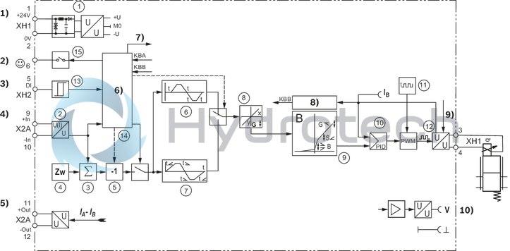
| 1) | Power supply |
| 2) | Ready for operation |
| 3) | Digital input |
| 4) | Command value |
| 5) | Actual value |
| 6) | Logic |
| 7) | Enable |
| 8) | Cable break |
| 9) | Enable |
| 10) | Measuring socket |
|
1 |
Power supply unit |
|
2 |
Differential amplifier |
|
3 |
Command value summing device |
|
4 |
Zero point setting |
|
5 |
Inverter |
|
6 |
Single ramp |
|
7 |
4-quadrant ramp |
|
8 |
Command value attenuator |
|
9 |
Characteristic curve generator |
|
10 |
Current controller |
|
11 |
Clock generator |
|
12 |
Output stage |
|
13 |
Enable or inverter or ramp off or 4Q ramp |
|
14 |
Switching logics/fault recognition |
|
15 |
Digital output |
Block diagram VT-MSPA2...
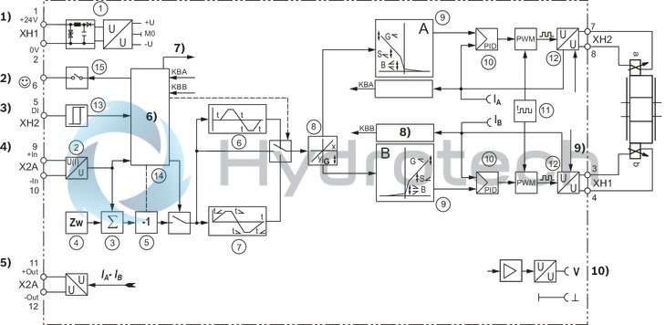
| 1) | Power supply |
| 2) | Ready for operation |
| 3) | Digital input |
| 4) | Command value |
| 5) | Actual value |
| 6) | Logic |
| 7) | Enable |
| 8) | Cable break |
| 9) | Enable |
| 10) | Measuring socket |
|
1 |
Power supply unit |
|
2 |
Differential amplifier |
|
3 |
Command value summing device |
|
4 |
Zero point setting |
|
5 |
Inverter |
|
6 |
Single ramp |
|
7 |
4-quadrant ramp |
|
8 |
Command value attenuator |
|
9 |
Characteristic curve generator |
|
10 |
Current controller |
|
11 |
Clock generator |
|
12 |
Output stage |
|
13 |
Enable or inverter or ramp off or 4Q ramp |
|
14 |
Switching logics/fault recognition |
|
15 |
Digital output |
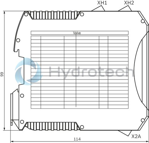
Dimensions in mm
Terminal assignment
|
Plug-in connector |
Terminal |
||
|
Operating voltage |
+UB |
XH1 |
1 |
|
0 V |
XH1 |
2 |
|
|
+ solenoid B |
XH1 |
3 |
|
|
- solenoid B |
XH1 |
4 |
|
|
Digital input |
XH2 |
5 |
|
|
Ready |
XH2 |
6 |
|
|
+ solenoid A 1) |
XH2 |
7 |
|
|
- solenoid A 1) |
XH2 |
8 |
|
|
+ command value |
X2A |
9 |
|
|
- command value |
X2A |
10 |
|
|
+ actual value |
X2A |
11 |
|
|
- actual value |
X2A |
12 |
|
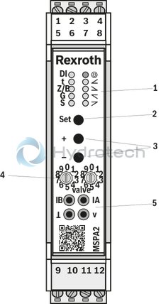
Device view
|
1 |
Status LEDs |
|
2 |
SET key |
|
3 |
+ / - keys |
|
4 |
Rotary switch |
|
5 |
Measuring sockets for connecting a measuring instrument |
Status description LEDs
|
Indicator light |
Operating state |
Display mode |
Meaning |
|
"Digital input" LED (yellow) |
Normal operation |
Permanent light on/off |
Digital input status |
|
Setup |
Flashing |
Standard setup active |
|
|
Setup |
Off |
Expert setup active |
|
|
Setup |
On/flashing/flickering |
Expert setup: Digital input setting |
|
|
"Ready" LED (red/green) |
Normal operation |
Permanent light green |
Module ready for operation |
|
Normal operation |
Permanent light red |
Error |
|
|
Normal operation and setup |
Flashing red/green |
Valve setting changed |
|
|
Normal operation and setup |
Flashing red |
Inadmissible valve number |
|
|
Normal operation |
Off |
Module not ready for operation |
|
|
Setup |
Flashing green |
Expert setup active |
Description of the LED display 1)
|
DI |
Enable 2) |
|
t |
Ramp |
|
Z/B |
Zero point / pilot current |
|
G |
Command value attenuator |
|
S |
Step level command value |
|
☺ |
Ready for operation |
 |
1st quadrant (positive command value rising) |
 |
2nd quadrant (positive command value falling) |
 |
3rd quadrant (positive command value rising) |
 |
4th quadrant (positive command value falling) |
| 1) | A detailed description is contained in the operating instructions 30232-B |
| 2) | Function of the digital input can be adjusted in the setup |
Product documentation for VT-MSPA..-2X:
Data sheet 30232 Operating instructions 30232-B CE declaration of conformity (available from Bosch Rexroth upon request) General information on the maintenance and commissioning of hydraulic components: Data sheet 07800 / 07900 Documentation on the Internet: www.boschrexroth.com/VT-MSPAx
Maintenance instructions:
The devices have been tested in the plant and are supplied with default settings. Only complete devices can be repaired. Repaired devices are returned with default settings. User-specific settings must be made by the machine end-user once again.
Notes:
In especially EMC-sensitive environments, additional measures must be taken (depending on the application, e.g. shielding, filtration) Wiring information Maximum possible spatial separation between signal and load lines. Do not lead signal lines through magnetic fields. If possible, install signal lines without intermediate terminals. Do not install signal lines in parallel to the load lines. Connect cable shields (see operating instructions 30232-B) For digital inputs and outputs as well as command and actual value, the max. admissible cable length for unshielded cables is 30 m. With longer cable lengths, shielded cables are to be used. The distance to radios must be sufficient (> 1m). With a strongly fluctuating operating voltage, it may in individual cases be necessary to use an external smoothing capacitor with a capacity of at least 2200 μF. Recommendation: Capacitor module VT 11110 (see data sheet 30750); sufficient for up to 3 amplifier modules. The upper and lower ventilation slots must not be concealed by adjacent devices in order to provide for sufficient cooling.Assignment switch position - valve type
|
VT-MSPA1 |
VT-MSPA2 |
||
|
Switch position |
Valve type |
Switch position |
Valve type |
|
0-0 |
no valve |
0-0 |
no valve |
|
0-1 |
4WRA6...-2X |
0-1 |
4WRA6...-2X |
|
0-2 |
4WRA10...-2X |
0-2 |
4WRA10...-2X |
|
0-3 |
4WRZ...-7X |
0-3 |
4WRZ...-7X |
|
0-4 |
3DREP6...-2X |
0-4 |
3DREP6...-2X |
|
0-5 |
4WRPH6...-2X (SO855) |
0-5 |
3DREP6...-2X (SO674) |
|
0-6 |
DBEP6...-1X |
0-6 |
- |
|
0-7 |
DBET-6X...G24... |
0-7 |
- |
|
0-8 |
DBET-6X...G24-8... |
0-8 |
- |
|
0-9 |
DBETX-1X...G24-25... |
0-9 |
- |
|
1-0 |
DBETX-1X...G24-8... |
1-0 |
- |
|
1-1 |
(Z)DBE6-2X... |
1-1 |
- |
|
1-2 |
DBEM10...-7X...G24... |
1-2 |
- |
|
1-3 |
DBEM10...-7X...G24-8... |
1-2 |
- |
|
1-4 |
DBEM20...-7X...G24... |
1-4 |
- |
|
1-5 |
DBEM20...-7X...G24-8... |
1-5 |
- |
|
1-6 |
DBEM30...-7X...G24... |
1-6 |
- |
|
1-7 |
DBEM30...-7X...G24-8... |
1-7 |
- |
|
1-8 |
(Z)DRE...-1X... |
1-8 |
- |
|
1-9 |
ZDRE10...-2X...G24... |
1-9 |
- |
|
2-0 |
ZDRE10...-2X...G24-8... |
2-0 |
- |
|
2-1 |
DRE...10...-6X...G24... |
2-1 |
- |
|
2-2 |
DRE...10...-6X...G24-8... |
2-2 |
- |
|
2-3 |
DRE...20...-6X...G24... |
2-3 |
- |
|
2-4 |
DRE...20...-6X...G24-8... |
2-4 |
- |
|
2-5 |
DRE...30...-6X...G24... |
2-5 |
- |
|
2-6 |
DRE...30...-6X...G24-8... |
2-6 |
- |
|
2-7 |
3DRE...-7X...G24... |
2-7 |
- |
|
2-8 |
3DRE...-7X...G24-8... |
2-8 |
- |
|
2-9 |
3FREX6...-1X...G24-25... |
2-9 |
- |
|
3-0 |
3FREX10...-1X...G24-25... |
3-0 |
- 9-8 |
|
3-1 |
3DREP6...-2X... (SO674) |
3-1 |
- |
|
3-4 |
- |
3-4 |
- |
|
3-5 |
- |
3-5 |
- |
|
3-6 |
- |
3-6 |
- |
|
3-7 |
Pump Control 1 (0,7 A) |
3-7 |
Pump Control 1 (0,74 A) |
|
3-8 |
Pump Control 2 (0,6 A) |
3-8 |
- |
|
3-9 |
Pump Control 3 (0,6 A) |
3-9 |
- |
|
9-6 |
Universal (0,8 A) |
9-6 |
Universal (0,8 A) |
|
9-7 |
Universal (1,6 A) |
9-7 |
Universal (1,6 A) |
|
9-8 |
Universal (2,5 A) |
9-8 |
Universal (2,5 A) |
Shield set for the installation with shielded lines
|
Type |
Material number |
Buy |
| SERVICE PACKAGE VT-HMC..-1X/M..SCHIR& | R961011117 | eShop |