

BOSCH REXROTH
R150234076
All Other Products
Std.-BSA NU 32x10 FDM-E-C C
BOSCH REXROTH
MATERIAL: R150234076
SUMMARY: Std.-BSA NU 32x10 FDM-E-C C
Due to extremely high demand, please call 888-651-5712 for availability
Technical data for nuts
|
Size |
C |
C0 |
vmax |
Mass |
|
d0 x P x Dw - i |
N |
N |
m/min |
kg |
| 16 x 5R x 3 - 4 | 14800 1) | 16100 1) | 30 2) | 0.29 |
| 20 x 5R x 3 - 4 | 17200 1) | 21500 1) | 0.53 | |
| 25 x 5R x 3 - 4 | 19100 1) | 27200 1) | 0.57 | |
| 25 x 10R x 3 - 4 | 18800 1) | 27000 1) | 60 2) | 0.77 |
| 32 x 5R x 3,5 - 4 | 25900 1) | 40000 1) | 23 2) | 0.96 |
| 32 x 10R x 3,969 - 5 | 38000 1) | 58300 1) | 47 2) | 1.34 |
| 40 x 5R x 3,5 - 5 | 34900 1) | 64100 1) | 19 2) | 1.68 |
| 40 x 10R x 6 - 4 | 60000 1) | 86400 1) | 38 2) | 2.15 |
| 40 x 10R x 6 - 6 | 86500 1) | 132200 1) | 2.73 | |
| 40 x 20R x 6 - 3 | 45500 1) | 62800 1) | 75 2) | 2.56 |
| 50 x 5R x 3,5 - 5 | 38400 1) | 81300 1) | 15 2) | 2.25 |
| 50 x 10R x 6 - 4 | 66500 1) | 109000 1) | 30 2) | 2.97 |
| 50 x 10R x 6 - 6 | 95600 1) | 166500 1) | 3.73 | |
| 50 x 20R x 6,5 - 5 | 90800 1) | 149700 1) | 60 2) | 4.93 |
| 63 x 10R x 6 - 4 | 74200 1) | 140500 1) | 24 2) | 4 |
| 63 x 10R x 6 - 6 | 106600 1) | 214300 1) | 4.45 | |
| 63 x 20R x 6,5 - 5 | 100700 1) | 190300 1) | 48 2) | 8.21 |
| 80 x 10R x 6,5 - 6 | 130100 1) | 291700 1) | 19 2) | 5.93 |
| 80 x 20R x 12,7 - 6 | 315200 1) | 534200 1) | 30 2) | 19.4 |
| 1) | The load ratings are valid for tolerance grades T3 and T5 only. For other tolerance grades, please take into account the correction factor fac (see General Technical Notes and Information "Technical Data", Technical Notes). |
| 2) | See "characteristic speed d0 • n" (see General Technical Notes and Information "Technical Data" (Technical Notes), and "Critical Speed ncr" (see General Technical Notes and Information, "Project planning notes") |
Operating conditions
|
Size |
Admissible operating temperature (min ... max) 1) |
Admissible storage temperature (min ... max) |
|
d0 x P x Dw - i |
||
| 16 x 5R x 3 - 4 | -10 °C ... +80 °C | -15 °C ... +80 °C |
| 20 x 5R x 3 - 4 | ||
| 25 x 5R x 3 - 4 | ||
| 25 x 10R x 3 - 4 | ||
| 32 x 5R x 3,5 - 4 | ||
| 32 x 10R x 3,969 - 5 | ||
| 40 x 5R x 3,5 - 5 | ||
| 40 x 10R x 6 - 4 | ||
| 40 x 10R x 6 - 6 | ||
| 40 x 20R x 6 - 3 | ||
| 50 x 5R x 3,5 - 5 | ||
| 50 x 10R x 6 - 4 | ||
| 50 x 10R x 6 - 6 | ||
| 50 x 20R x 6,5 - 5 | ||
| 63 x 10R x 6 - 4 | ||
| 63 x 10R x 6 - 6 | ||
| 63 x 20R x 6,5 - 5 | ||
| 80 x 10R x 6,5 - 6 | ||
| 80 x 20R x 12,7 - 6 |
| 1) | Ball screw assemblies are suitable for continuous operation at temperatures up to 80 °C with temporary peaks of 100 °C (measurements taken on the outer shell of the nut). |
Legend
|
Symbol |
Description |
Unit |
|
d0 |
Nominal diameter |
mm |
|
P |
Lead (R = right-hand) |
|
|
Dw |
Ball diameter |
mm |
|
i |
Number of ball track turns |
|
|
C |
Dynamic load capacity |
N |
|
C0 |
Static load capacity |
N |
|
vmax |
Maximum permissible speed |
m/min |
Technical notes

| 1) | Lube port at flange center (lube port machining: Flat surface L3 ≤ 15 mm, countersink L3 > 15 mm) |
| 2) | Nut rework: Axial lube port |
Dimensions
|
Size |
d1 |
d2 |
D1 |
D5 |
Hole pattern |
D6 |
D7 |
L |
L3 |
L4 |
L9 1) |
L10 |
S 2) |
Sx |
|
d0 x P x Dw - i |
g6 |
|||||||||||||
|
mm |
mm |
mm |
mm |
mm |
mm |
mm |
mm |
mm |
mm |
mm |
mm |
mm |
||
| 16 x 5R x 3 - 4 | 15 | 12.9 | 28 | 48 | BB2 | 38 | 5.5 | 72 | 12 | 10 | 44 | 60 | M6 | 4 |
| 20 x 5R x 3 - 4 | 19 | 16.9 | 36 | 58 | 47 | 6.6 | 82 | 51 | 70 | |||||
| 25 x 5R x 3 - 4 | 24 | 21.9 | 40 | 62 | 51 | 55 | ||||||||
| 25 x 10R x 3 - 4 | 120 | 16 | 108 | |||||||||||
| 32 x 5R x 3,5 - 4 | 31 | 28.4 | 50 | 80 | 65 | 9 | 88 | 13 | 10 | 71 | 75 | |||
| 32 x 10R x 3,969 - 5 | 27.9 | 146 | 16 | 133 | ||||||||||
| 40 x 5R x 3,5 - 5 | 39 | 36.4 | 63 | 93 | BB1 | 78 | 100 | 15 | 10 | 81.5 | 85 | M8x1 | 5 | |
| 40 x 10R x 6 - 4 | 38 | 33.8 | 140 | 16 | 125 | |||||||||
| 40 x 10R x 6 - 6 | 180 | 165 | ||||||||||||
| 40 x 20R x 6 - 3 | 175 | 25 | 160 | |||||||||||
| 50 x 5R x 3,5 - 5 | 49 | 46.4 | 75 | 110 | 93 | 11 | 100 | 10 | 97.5 | 85 | ||||
| 50 x 10R x 6 - 4 | 48 | 43.8 | 140 | 18 | 16 | 122 | ||||||||
| 50 x 10R x 6 - 6 | 180 | 162 | ||||||||||||
| 50 x 20R x 6,5 - 5 | 43.3 | 255 | 25 | 237 | ||||||||||
| 63 x 10R x 6 - 4 | 61 | 56.8 | 90 | 125 | 108 | 140 | 22 | 16 | 110 | 118 | ||||
| 63 x 10R x 6 - 6 | 180 | 158 | ||||||||||||
| 63 x 20R x 6,5 - 5 | 56.3 | 95 | 135 | 115 | 13.5 | 255 | 25 | 117.5 | 233 | |||||
| 80 x 10R x 6,5 - 6 | 78 | 73.3 | 105 | 145 | 125 | 190 | 16 | 127.5 | 168 | |||||
| 80 x 20R x 12,7 - 6 | 76 | 67 | 125 | 165 | 145 | 340 | 25 | 25 | 147.5 | 315 |
| 1) | Flange type B (two flat surfaces) option available! |
| 2) | Lube port machining: Flat surface L3 ≤ 15 mm, countersink L3 > 15 mm |
Legend
|
Symbol |
Description |
Unit |
|
d0 |
Nominal diameter |
mm |
|
P |
Lead (R = right-hand) |
|
|
Dw |
Ball diameter |
mm |
|
i |
Number of ball track turns |
Attention: When setting up applications, do not allow components to collide with the front lube unit.
Nut housing MGD
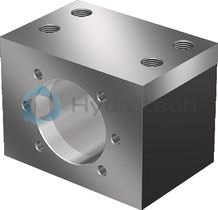
Nut housing MGD
Steel nut housings MGD are designed for FEM-E-C, FDM-E-C, SEM-E-C and FED-E-B nutsCatalog
Service
CAD data
Front lube unit – ball screw assembly

Front lube unit – ball screw assembly
Catalog
Service
Arrestor nut

Arrestor nut
Catalog
Service
Flange type B available. See general technical notes and information, “Codes”
Supplied only as complete ball screw assembly.
Required and supplementary documentation
For further instructions and information, please refer to the documentation for this product.
You can find PDF files of these documents on the Internet at www.boschrexroth.com/mediadirectory.
If you are unsure about using this product, please contact Bosch Rexroth.
Notes