

BOSCH REXROTH
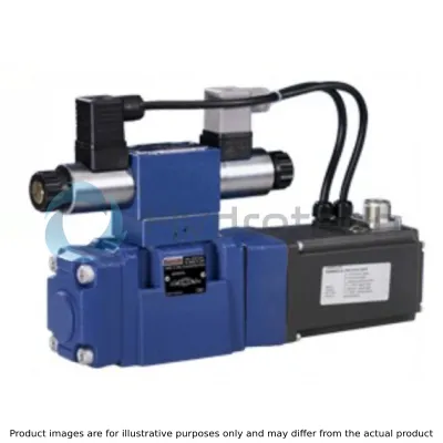
4WRKE25W8-350L-3X/6EG24K31/A1D3M
R900249554
Proportional Directional Valves
Prop. dir. valves: WRK* 25.-3x/
BOSCH REXROTH
MATERIAL: R900249554
SUMMARY: Prop. dir. valves: WRK* 25.-3x/
Quantity in stock: 0
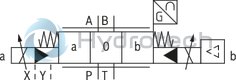
Pilot control valve type 4WRAP 6 W7.3X/G24… (1st stage)
The pilot control valve is a direct operated proportional valve. The control edge geometry has been optimized for the use as pilot control valve for proportional directional valves type 4WRKE. The proportional solenoids are pressure-tight, wet-pin DC solenoids with detachable coils. They convert the electric current proportionally into mechanical force. An increase of the current results in a correspondingly higher solenoid force. The set solenoid force will remain constant over the entire control stroke.
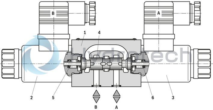
The pilot control valve mainly consists of the housing (1), the proportional solenoid (2 and 3), the valve control spool (4) and springs (5 and 6). In non-actuated state both actuators are connected to the tank. If one of the two solenoids (2 or 3) is excited, the magnetic force will move the valve control spool (4) towards the spring (5 or 6). After having overcome the overlap area, the connection of one of the two actuators to the tank is blocked and the connection to the pressure chamber is made. There is a flow from P to the control chamber of the main stage.
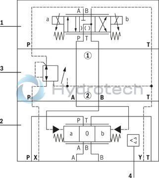
Valves of type 4WRKE are 2-stage proportional directional valves. They control the flow direction and size. The main stage is position-controlled so that the control spool position is independent from flow forces also in the case of bigger flows.
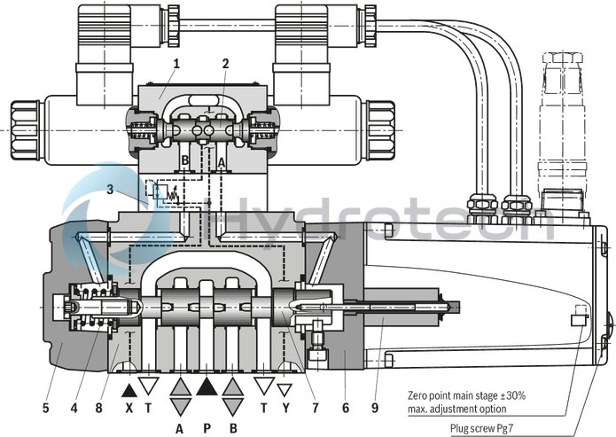
The valves mainly consist of the pilot control valve (1), the housing (8), the main control spool (7), the covers (5 and 6), the centering spring (4), the inductive position transducer (9) and the pressure reducing valve (3). If there is no input signal, the main control spool (7) will be kept in the central position by the centering spring (4). Both control chambers in the covers (5 and 6) are connected to the tank via the valve control spool (2). The main control spool (7) is connected to suited control electronics via the inductive position transducer (9). Both the position change of the main control spool (7) and the change of the command value at the junction summing of the amplifier create a voltage difference. During the comparison of command value and actual value, a possible control deviation is determined via the electronics and the proportional solenoid of the pilot control valve (1) is supplied with current. The current induces a force in the solenoid which operates the control spool via a plunger in a row. The flow which is activated via the control cross-sections leads to an adjustment of the main control spool. The main control spool (7) with the core of the inductive position transducer (9) attached to it is displaced until the actual value corresponds to the command value. In controlled state, the main control spool (7) is force-balanced and kept in this controlled position. The control spool stroke and the control opening change proportionally to the command value. The control electronics is integrated in the valve. By adjusting valve and electronics, the deviation in series production of the devices is kept low.
The tank lines must not be allowed to run empty; with corresponding installation conditions, a preload valve (preload pressure approx. 2 bar) must be installed.
Valve particularities
The 2nd stage is basically set-up of modules of our proportional valves. The zero point adjustment at "zero point main stage" is made at the factory and can be adjusted in a range of ± 30% of the nominal stroke via a potentiometer in the control electronics. Access in the integrated control electronics by removing a plug screw on the front side of the cover housing. When the pilot control valve or the control electronics are exchanged, they are to be re-adjusted. All adjustments may be implemented by instructed experts only.
Notice!
Changes in the zero point may result in damage to the system and may only be implemented by instructed specialists!
|
01 |
02 |
03 |
04 |
05 |
06 |
07 |
08 |
09 |
10 |
11 |
12 |
13 |
14 |
15 |
|||
|
4 |
WRKE |
‒ |
3X |
/ |
6E |
G24 |
K31 |
/ |
D3 |
* |
|
01 |
4 main ports |
4 |
|
02 |
Proportional directional valve with electrical position feedback and integrated electronics (OBE) |
WRKE |
|
03 |
Size 10 |
10 |
|
Size 16 |
16 |
|
|
Size 25 |
25 |
|
|
Size 27 |
27 |
|
|
Size 32 |
32 |
|
|
Size 35 |
35 |
|
|
04 |
Symbols; for the possible version, see "Symbols/Circuit diagrams" |
E; E1-; E3-; W6-; W8-; R; R3; EA; W6A; EB; W6B |
|
Rated flow NG10 |
||
|
05 |
25 l/min |
25 1) |
|
50 l/min |
502) |
|
|
100 l/min |
100 |
|
|
Rated flow NG16 |
||
|
05 |
125 l/min |
1252) |
|
150 l/min |
1502) |
|
|
200 l/min |
200 |
|
|
220 l/min |
220 |
|
|
Rated flow NG25 |
||
|
05 |
220 l/min |
220 |
|
350 l/min |
350 |
|
|
Rated flow NG27 |
||
|
05 |
500 l/min |
500 |
|
Size 32 |
||
|
05 |
400 l/min |
400 |
|
600 l/min |
600 |
|
|
Size 35 |
||
|
05 |
1000 l/min |
1000 |
|
Characteristic curve form |
||
|
06 |
Linear |
L |
|
Linear with fine control range |
P |
|
|
07 |
Component series 30 ... 39 (30 ... 39: unchanged installation and connection dimensions) |
3X |
|
08 |
Pilot control valve NG6 |
6E |
|
09 |
Supply voltage 24 V |
G24 |
|
Pilot oil supply and return |
||
|
10 |
External pilot oil supply, external pilot oil return |
no code |
|
Internal pilot oil supply, external pilot oil return |
E |
|
|
Pilot oil supply internal, pilot oil return internal |
ET |
|
|
External pilot oil supply, internal pilot oil return |
T |
|
|
Electrical connection |
||
|
11 |
Without mating connector, with connector according to DIN EN 175301-804, separate order |
K31 |
|
Electrical interface |
||
|
12 |
Command value/actual value ± 10 mA |
C1 |
|
Command value/actual value ±10 V |
A1 3) |
|
|
Command value/actual value ±10 V |
A5 |
|
|
Command value/actual value 4 ... 20 mA |
F1 |
|
|
13 |
With pressure reducing valve ZDR 6 DP0-4X/40YM-W80 (fixedly set) |
D3 |
|
14 |
NBR seals |
M |
|
FKM seals |
V |
|
|
15 |
Further details in the plain text |
* |
|
1) |
Only E and W6- with characteristic curve form L (linear) available |
|
|
2) |
Only E1- and W8- with characteristic curve form L (linear) available |
|
|
3) |
When replacing the component series 2X by 3X, the electronics interface A5 is to be defined (enable signal at pin C |
|
For applications outside these parameters, please consult us!
general
|
Type |
4WRKE | ||||||
|
Size |
10 | 16 | 25 | 27 | 32 | 35 | |
|
Installation position |
any, preferably horizontal | ||||||
|
Ambient temperature range |
°C |
-20 … +50 | |||||
|
Storage temperature range |
°C |
-20 … +80 | |||||
|
Weight |
kg |
8.7 | 11.2 | 16.8 | 17 | 31.5 | 34 |
|
Sine test according to DIN EN 60068-2-6 |
10 cycles, 10…2000.. 10 Hz with logarithmic frequency changing speed of 1 octave/min, 5 to 57 Hz, amplitude 1.5 mm (p-p), 57 to 2000 Hz, amplitude 10g, 3 axes | ||||||
|
Noise test according to DIN EN 60068-2-64 |
20…2000 Hz, amplitude 0.05g2/Hz (10gRMS) 3 axes, testing time 30 min per axis | ||||||
|
Shock test according to DIN EN 60068-2-27 |
Half-sine 15g / 11 ms, 3 times in positive and 3 times in negative direction per axis, 3 axes | ||||||
|
Damp heat according to DIN EN 60068-2-30 |
Variant 2: +25 °C … +55 °C, 90 % … 97 % relative humidity, 2 cycles á 24 hours | ||||||
hydraulic
|
Size |
10 | 16 | 25 | 27 | 32 | 35 | |||
|
Maximum operating pressure |
bar |
350 | |||||||
|
Maximum operating pressure |
Port P |
bar |
315 | 350 | 210 | 350 | |||
|
Port A |
bar |
315 | 350 | 210 | 350 | ||||
|
Port B |
bar |
315 | 350 | 210 | 350 | ||||
|
Operating pressure range |
Pilot control valve, pilot oil supply |
bar |
25 … 315 | ||||||
|
Maximum return flow pressure |
Port T, external pilot oil return |
bar |
315 | 250 | 210 | 250 | |||
|
Port T, internal pilot oil return |
bar |
10 | |||||||
|
Port Y |
bar |
10 | |||||||
|
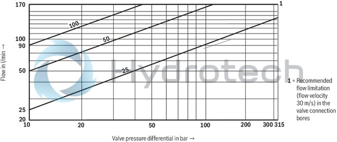
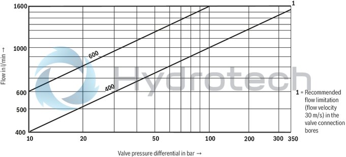
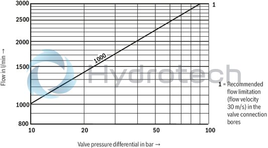
Maximum flow |
l/min |
170 | 460 | 870 | 1000 | 1600 | 3000 | ||
|
Nominal flow 1) |
l/min |
25 50 100 |
125 150 200 220 |
220 350 |
500 |
400 600 |
1000 | ||
|
Pilot flow |
input signal 0 → 100% |
Port X and Y |
l/min |
4.1 | 8.5 | 11.7 | 13 | ||
|
Hydraulic fluid temperature range |
°C |
-20 … +80 | |||||||
|
preferably |
°C |
-40 … +50 | |||||||
|
Viscosity range |
mm²/s |
20 … 380 | |||||||
|
preferably |
mm²/s |
30 … 45 | |||||||
|
Maximum admissible degree of contamination of the hydraulic fluid, cleanliness class according to ISO 4406 (c) 2) |
Pilot control valve |
Class 18/16/13 according to ISO 4406 (c) | |||||||
|
Main valve |
Class 20/18/15 according to ISO 4406 (c) | ||||||||
|
Hysteresis |
% |
≤ 1 | |||||||
|
Response sensitivity |
% |
≤ 0.5 | |||||||
| 1) | ±10% with Δp = 10 bar, Δp = valve pressure differential |
| 2) | The cleanliness classes specified for the components must be adhered to in hydraulic systems. Effective filtration prevents faults and simultaneously increases the life cycle of the components. For the selection of the filters, see www.boschrexroth.com/filter. |
electrical
|
Size |
10 | 16 | 25 | 27 | 32 | 35 | ||
|
Voltage type |
Direct voltage | |||||||
|
Type of signal |
analog | |||||||
|
Maximum current consumption |
of the amplifier |
A |
1.5 | |||||
|
of the amplifier (impulse current) |
A |
3 | ||||||
|
Protection class according to DIN EN 60529 |
IP65 (with mating connector mounted and locked) | |||||||
|
Power supply |
V |
24 | ||||||
|
Supply voltage range |
V |
18 … 35 | ||||||
|
Earthing (GND) |
V |
0 | ||||||
|
Command value input |
"A1" |
V |
10 | |||||
|
Command value input range |
"F1" |
mA |
4 … 20 | |||||
|
Actual value output |
"A1" |
V |
10 | |||||
|
Actual value output range |
"F1" |
mA |
4 … 20 | |||||
|
Hydraulic fluid |
Classification |
Suitable sealing materials |
Standards |
|
Mineral oils and related hydrocarbons |
HL, HLP |
NBR / FKM |
DIN 51524 |
|
Flame-resistant - containing water |
HFC (Fuchs HYDROTHERM 46M, Petrofer Ultra Safe 620) |
NBR |
ISO 12922 |
|
Phosphoric acid esters |
HFD-R |
FKM |
|
|
Important information on hydraulic fluids: For more information and data on the use of other hydraulic fluids please contact us. There may be limitations regarding the technical valve data (temperature, pressure range, life cycle, maintenance intervals, etc.). The flash point of the process and operating medium used must be 40 K over the maximum solenoid surface temperature.
Flame-resistant - containing water: |
|||
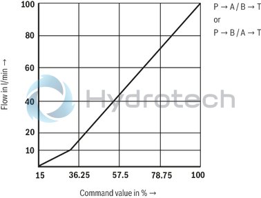
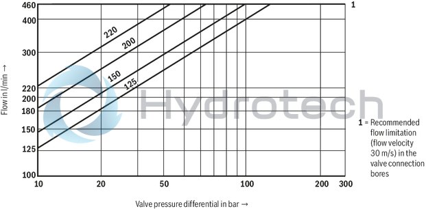
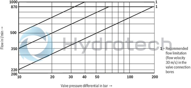
(measured with HLP46, ϑÖl = 40 ±5 °C)
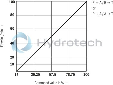
Control spool E, W, and R
Characteristic curve L
Control spool E, W, and R
Characteristic curve P
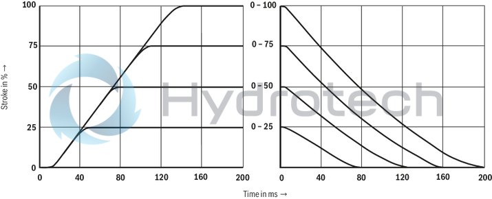
Transition function with stepped electric input signals
Size 10
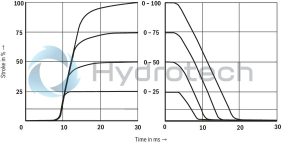
Load function with maximum valve opening; tolerance ±10 %
Size 10
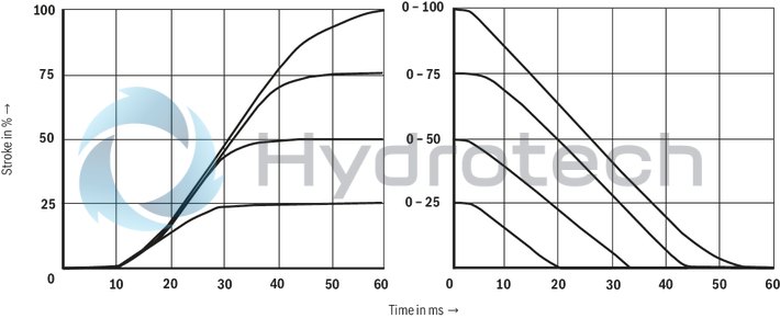
Transition function with stepped electric input signals
Size 16
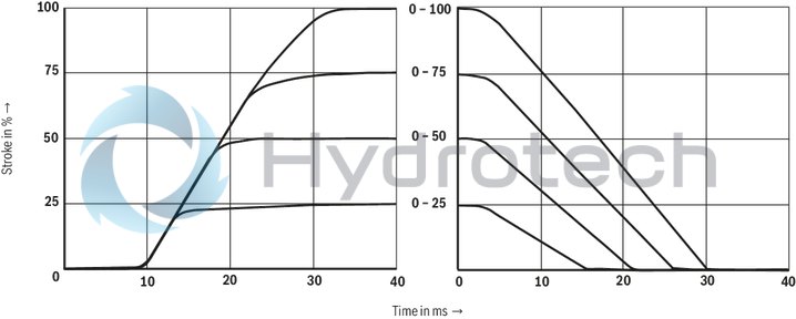
Load function with maximum valve opening; tolerance ±10 %
Size 16
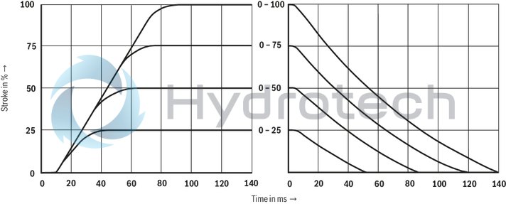
Transition function with stepped electric input signals
Size 25, Size 27
Load function with maximum valve opening; tolerance ±10 %
Size 25, Size 27
Transition function with stepped electric input signals
Size 32
Load function with maximum valve opening; tolerance ±10 %
Size 32
Transition function with stepped electric input signals
Size 35
Load function with maximum valve opening; tolerance ±10 %
Size 35
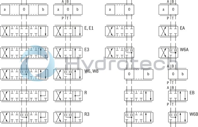
Symbols
|
With symbols E1- and W8-, the following applies: |
|
|
P → A: qvmax |
B → T: qv/2 |
|
P → B: qv/2 |
A → T: qvmax |
|
With symbols R and R3-, the following applies: |
|
|
P → A: qvmax |
B → P: qv/2 |
|
P → B: qv/2 |
A → T: qvmax |
|
With control spool symbols W6-, W8- and R3-, there is - in the zero position - a connection from A → T and B → T with approx. 2 % of the relevant nominal cross-section. |
|
simplified
External pilot oil supply, external pilot oil return
Detailed
|
1 |
Pilot control valve |
|
2 |
Main valve |
|
3 |
Pressure reducing valve |
|
4 |
Integrated electronics (OBE) |
|
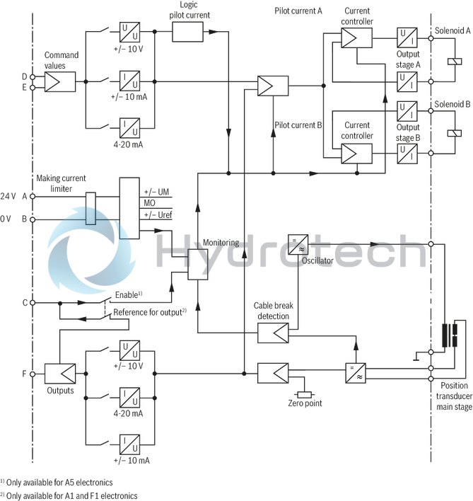
Pin assignment |
Contact |
Assignment interface "A1" |
Assignment interface "F1" |
Signal with interface A5 |
|
Power supply |
A |
24 V (18 V to 35 V), Imax = 1.5 A; impulse load ≤ 3 A |
||
|
B |
0 V |
|||
|
Reference (actual value) |
C |
Reference potential actual value |
Enable 4 to 24 V |
|
|
Differential amplifier input (command value) |
D |
± 10 V |
4 ... 20 mA |
± 10 V |
|
(command value) |
E |
0V reference potential to pin D |
0 V reference potential for pin D and F |
|
|
Measuring output (actual value) |
F |
± 10 V |
4 ... 20 mA |
± 10 V |
|
PE |
connected to cooling element and valve housing |
|||
Command value:
Positive command value at D and reference potential at E result in flow from P → A and B → T.Negative command value at D and reference potential at E result in flow from P → B and A → T.
Connection cable:
Recommendation:
up to 25 m cable length type LiYCY 7 x 0.75 mm² up to 50 m cable length type LiYCY 7 x 1.0 mm² Connect shield to PE only on the supply side.Notice:
Electrical signals provided via control electronics (e. g. actual value) must not be used for switching off safety-relevant machine functions.
Block diagram / pin assignment
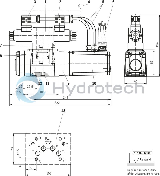
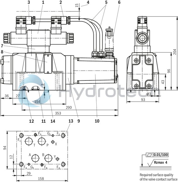
Size 10
Dimensions in mm
|
1 |
Pilot control valve |
|
2 |
Mating connector "A", color gray |
|
3 |
Mating connector "B", color black |
|
4 |
Space required for the connection cable and to remove the mating connector |
|
5 |
Cabling |
|
6 |
Mating connector, separate order |
|
7 |
"D3” pressure reducing valve |
|
8 |
Name plate |
|
9 |
Main valve |
|
10 |
Integrated electronics (OBE) |
|
11 |
Identical seal rings for ports A, B, P, and T |
|
12 |
Identical seal rings for ports X and Y |
|
13 |
Machined valve contact surface; Porting pattern according to ISO 4401-05-05-0-05 |
Recommended valve mounting screws (separate order):
4 hexagon socket head cap screws ISO 4762 - M6 x 45 - 10.9-flZn-240h-LTightening torque MA = 13.5 Nm ± 10 %, material no. R913000258 or
4 hexagon socket head cap screws ISO 4762 - M6 x 45 - 10.9Tightening torque MA = 15.5 Nm ± 10 %
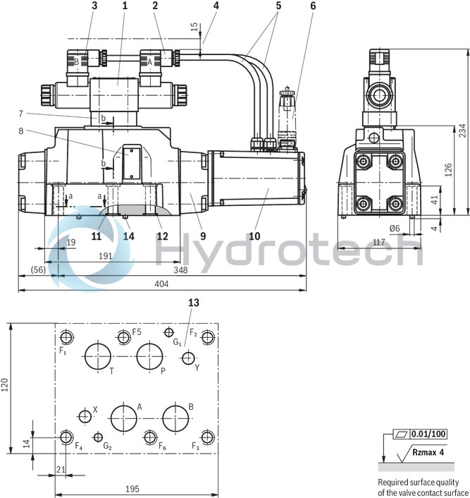
Size 16
Dimensions in mm
|
1 |
Pilot control valve |
|
2 |
Mating connector "A", color gray |
|
3 |
Mating connector "B", color black |
|
4 |
Space required for the connection cable and to remove the mating connector |
|
5 |
Cabling |
|
6 |
Mating connector, separate order |
|
7 |
"D3” pressure reducing valve |
|
8 |
Name plate |
|
9 |
Main valve |
|
10 |
Integrated electronics (OBE) |
|
11 |
Identical seal rings for ports A, B, P, and T |
|
12 |
Identical seal rings for ports X and Y |
|
13 |
Machined valve contact surface; Porting pattern according to ISO 4401-07-07-0-05 |
|
14 |
Locking pin |
Recommended valve mounting screws (separate order):
2 hexagon socket head cap screws ISO 4762 - M6 x 60 - 10.9-flZn-240h-LTightening torque MA = 12.2 Nm ± 10 % , material no. R913000115
4 hexagon socket head cap screws ISO 4762 - M10 x 60 - 10.9-flZn-240h-LTightening torque MA = 58 Nm ± 20 %, material no. R913000116 or
2 hexagon socket head cap screws ISO 4762 - M6 x 60 - 10.9
Tightening torque MA = 15.5 Nm ± 10 %
4 hexagon socket head cap screws ISO 4762 - M10 x 60 - 10.9
Tightening torque MA = 75 Nm ± 20 %
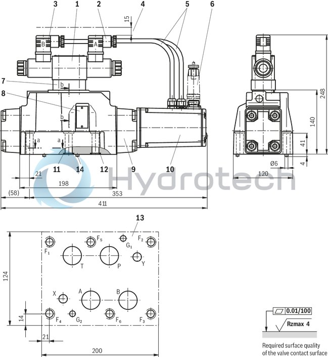
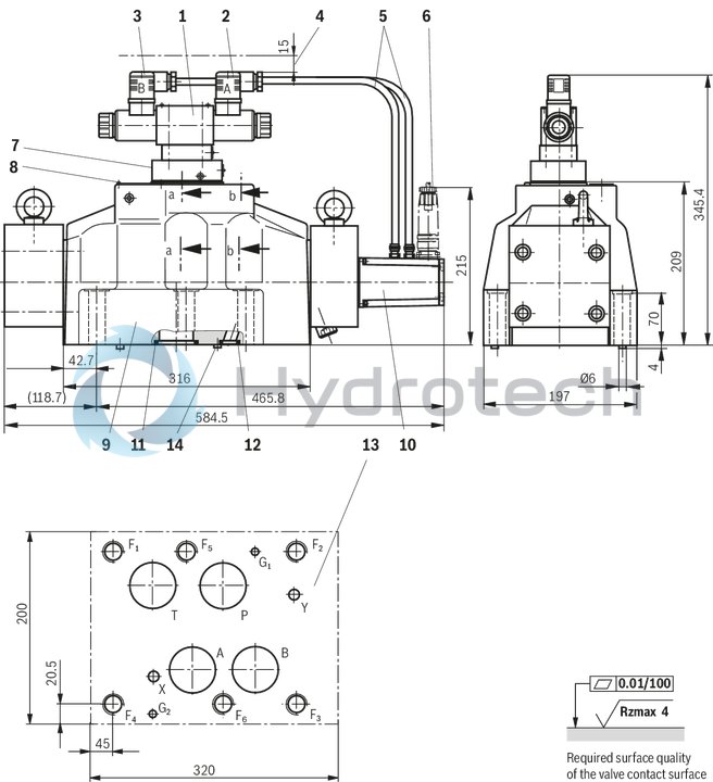
NG25
Dimensions in mm
|
1 |
Pilot control valve |
|
2 |
Mating connector "A", color gray |
|
3 |
Mating connector "B", color black |
|
4 |
Space required for the connection cable and to remove the mating connector |
|
5 |
Cabling |
|
6 |
Mating connector, separate order |
|
7 |
"D3” pressure reducing valve |
|
8 |
Name plate |
|
9 |
Main valve |
|
10 |
Integrated electronics (OBE) |
|
11 |
Identical seal rings for ports A, B, P, and T |
|
12 |
Identical seal rings for ports X and Y |
|
13 |
Machined valve contact surface; Porting pattern according to ISO 4401-08-08-0-05 (ports X and Y as required) |
|
14 |
Locking pin |
NG27
Dimensions in mm
|
1 |
Pilot control valve |
|
2 |
Mating connector "A", color gray |
|
3 |
Mating connector "B", color black |
|
4 |
Space required for the connection cable and to remove the mating connector |
|
5 |
Cabling |
|
6 |
Mating connector, separate order |
|
7 |
"D3” pressure reducing valve |
|
8 |
Name plate |
|
9 |
Main valve |
|
10 |
Integrated electronics (OBE) |
|
11 |
Identical seal rings for ports A, B, P, and T |
|
12 |
Identical seal rings for ports X and Y |
|
13 |
Machined valve contact surface; Porting pattern according to ISO 4401-08-08-0-05 (Ports X, Y as required) |
|
14 |
Locking pin |
Recommended valve mounting screws (separate order):
6 hexagon socket head cap screws ISO 4762 - M12 x 60 - 10.9-flZn-240h-LTightening torque MA = 100 Nm ± 20 %, material no. R913000121 or
6 hexagon socket head cap screws ISO 4762 - M12 x 60 - 10.9Tightening torque MA = 130 Nm ± 20 %
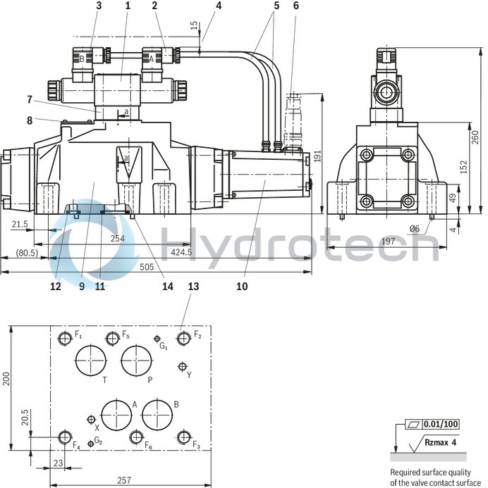
Size 32
Dimensions in mm
|
1 |
Pilot control valve |
|
2 |
Mating connector "A", color gray |
|
3 |
Mating connector "B", color black |
|
4 |
Space required for the connection cable and to remove the mating connector |
|
5 |
Cabling |
|
6 |
Mating connector, separate order |
|
7 |
"D3” pressure reducing valve |
|
8 |
Name plate |
|
9 |
Main valve |
|
10 |
Integrated electronics (OBE) |
|
11 |
Identical seal rings for ports A, B, P, and T |
|
12 |
Identical seal rings for ports X and Y |
|
13 |
Machined valve contact surface; Porting pattern according to ISO 4401-10-09-0-05 (Ports X and Y as required) |
|
14 |
Locking pin |
Recommended valve mounting screws (separate order):
6 hexagon socket head cap screws ISO 4762 - M20 x 80 - 10.9-flZn-240h-LTightening torque MA = 340 Nm ± 20 %, material no. R901035246 or
4 hexagon socket head cap screws ISO 4762 - M20 x 80 - 10.9Tightening torque MA = 430 Nm ± 20 %
Size 35
Dimensions in mm
|
1 |
Pilot control valve |
|
2 |
Mating connector "A", color gray |
|
3 |
Mating connector "B", color black |
|
4 |
Space required for the connection cable and to remove the mating connector |
|
5 |
Cabling |
|
6 |
Mating connector, separate order |
|
7 |
"D3” pressure reducing valve |
|
8 |
Name plate |
|
9 |
Main valve |
|
10 |
Integrated electronics (OBE) |
|
11 |
Identical seal rings for ports A, B, P, and T |
|
12 |
Identical seal rings for ports X and Y |
|
13 |
Machined valve contact surface; Porting pattern according to ISO 4401-10-09-0-05 (Ports X and Y as required) |
|
14 |
Locating pins |
Recommended valve mounting screws (separate order):
6 hexagon socket head cap screws ISO 4762 - M20 x 100 - 10.9-flZn-240h-LTightening torque MA = 465 Nm ± 20 %, material no. R913000386 or
6 hexagon socket head cap screws ISO 4762 - M20 x 100 - 10.9Tightening torque MA = 610 Nm ± 20 %
Mating connectors for valves with round connector, 6-pole + PE
7P Z31
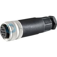
Mating connectors for valves with round connector, 6-pole + PE
7P Z31
For valves with round connector according to EN 175201-804, 6-pole + PE as well as 6-pole, compatible with VG 95328Data sheet
Spare parts & repair