BOSCH REXROTH
Z2DB10VD2-4X/200V
R900411358
Pressure Relief Valves
Pressure valves: ZDB,Z2DB 10.-4x/
BOSCH REXROTH
MATERIAL: R900411358
SUMMARY: Pressure valves: ZDB,Z2DB 10.-4x/
Quantity in stock: 0
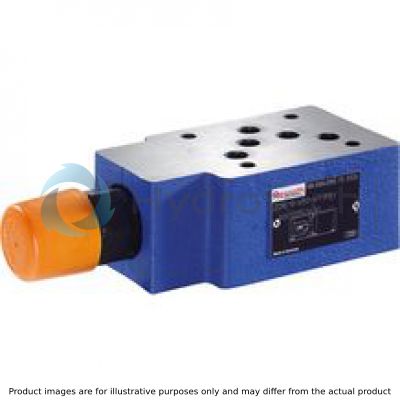
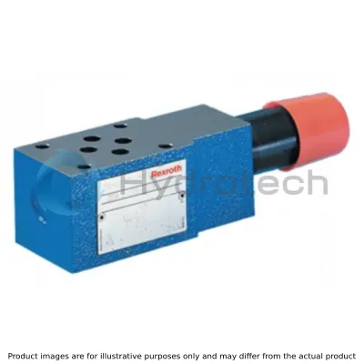
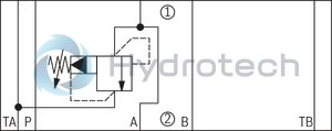
Pressure valves of type ZDB and Z2DB are pilot-operated pressure relief valves in sandwich plate design. They are used for limiting a system pressure. The valves basically consist of the housing (7) and one or two pressure valve cartridges. The system pressure can be set via the adjustment type (4).
In the initial position the valves are closed. The pressure in channel A acts on the spool (1). At the same time, pressure is applied to the spring-loaded side of the spool (1) via nozzle (2) and to the pilot poppet (6) via nozzle (3).
If the pressure in channel A exceeds the value set at the spring (5), the pilot poppet (6) opens. Hydraulic fluid flows from the spring-loaded side of the spool (1), nozzle (3) and channel (8) into channel T (TA). The resulting pressure drop moves the spool (1) and opens the connection from A to T (TA). In channel A, the pressure set at the spring (5) settles.
Type ZDB 10 VA2-4X/…V
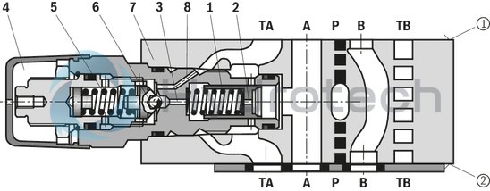
➀ = component side
➁ = plate side
|
01 |
02 |
03 |
04 |
05 |
06 |
07 |
08 |
09 |
10 |
11 |
||
|
Z |
DB |
10 |
– |
4X |
/ |
* |
|
01 |
Sandwich plate |
Z |
|
02 |
1 pressure valve cartridge (only with version “VA”, “VB”. “VT” and “VP”) |
no code |
|
2 pressure valve cartridges (only with version “VC” and “VD”) |
2 |
|
|
03 |
Pressure relief valve |
DB |
|
04 |
Size 10 |
10 |
|
Relief function from – to: |
||
|
05 |
A – TA |
VA |
|
P – TA |
VP |
|
|
TB1 – TA2 |
VT |
|
|
B – TB |
VB |
|
|
A – TA and B – TB |
VC |
|
|
A – B and B – A |
VD |
|
|
Adjustment type for pressure adjustment |
||
|
06 |
Rotary knob |
1 |
|
Sleeve with hexagon and protective cap |
2 |
|
|
Lockable rotary knob with scale 1) |
3 |
|
|
Rotary knob with scale |
7 |
|
|
07 |
Component series 40 … 49 (40 … 49: unchanged installation and mounting dimensions) |
4X |
|
08 |
Set pressure up to 50 bar |
50 |
|
Set pressure up to 100 bar |
100 |
|
|
Set pressure up to 200 bar |
200 |
|
|
Set pressure up to 315 bar |
315 |
|
|
Corrosion resistance |
||
|
09 |
None |
no code |
|
Improved corrosion protection (240 h salt spray test according to EN ISO 9227) |
J3 2) |
|
|
High corrosion protection (720 h salt spray test according to EN ISO 9227) |
J5 2) |
|
|
Seal material |
||
|
10 |
NBR seals |
no code |
|
FKM seals |
V |
|
|
Observe compatibility of seals with hydraulic fluid used. (Other seals upon request) |
||
|
11 |
Further details in the plain text |
* |
| 1) | Key with material no. R900008158 is included in the scope of delivery. |
| 2) | Only with adjustment type "2", however without protective cap |
Notice:
To port X and Y bored according to ISO 4401-05-05-0-05 (e.g. for pilot-operated directional valve NG10), version “SO30“ applies at the end of the ordering code.
general
|
Size |
10 | ||
|
Weight (approx.) |
Type ZDB |
kg |
2.4 |
|
Type Z2DB |
kg |
2.6 | |
|
Installation position |
any | ||
|
Ambient temperature range |
°C |
-20 … +80 | |
hydraulic
|
Size |
10 | |
|
Maximum operating pressure |
bar |
315 |
|
Maximum set pressure |
bar |
50 100 200 315 |
|
Maximum flow |
l/min |
100 |
|
Hydraulic fluid |
see table | |
|
Hydraulic fluid temperature range |
°C |
-20 … +80 |
|
Viscosity range |
mm²/s |
10 … 800 |
|
Maximum admissible degree of contamination of the hydraulic fluid 1) |
Class 20/18/15 according to ISO 4406 (c) | |
| 1) | The cleanliness classes specified for the components must be adhered to in hydraulic systems. Effective filtration prevents faults and simultaneously increases the life cycle of the components. For the selection of the filters, see www.boschrexroth.com/filter. |
|
Hydraulic fluid |
Classification |
Suitable sealing materials |
Standards |
Data sheet |
|
|
Mineral oil |
HL, HLP |
FKM, NBR |
DIN 51524 |
90220 |
|
|
Bio-degradable 1) |
Insoluble in water |
HETG |
FKM |
ISO 15380 |
90221 |
|
HEES |
FKM |
||||
|
Soluble in water |
HEPG |
FKM |
ISO 15380 |
||
|
Flame-resistant |
Water-free |
HFDU (glycol base) |
FKM |
ISO 12922 |
90222 |
|
HFDU (ester base) 1) |
FKM |
||||
|
HFDR |
FKM |
||||
|
Containing water |
HFC (Fuchs Hydrotherm 46M, Petrofer Ultra Safe 620) |
NBR |
ISO 12922 |
90223 |
|
|
Important information on hydraulic fluids: For further information and data on the use of other hydraulic fluids, please refer to the data sheets above or contact us. There may be limitations regarding the technical valve data (temperature, pressure range, life cycle, maintenance intervals, etc.). The ignition temperature of the hydraulic fluid used must be 50 K higher than the maximum surface temperature. Flame-resistant – containing water: Maximum pressure differential 210 bar, otherwise, increased cavitation erosion Life cycle as compared to operation with mineral oil HL, HLP 30 … 100% Maximum hydraulic fluid temperature 60 °C Bio-degradable and flame-resistant: If this hydraulic fluid is used, small amounts of dissolved zinc may get into the hydraulic system. |
|||||
| 1) | Not recommended for corrosion-protected version "J3" and "J5" (contains zinc) |
For applications outside these parameters, please consult us!
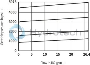
(measured with HLP46, ϑOil = 40 ±5 °C)
pE-qV characteristic curves
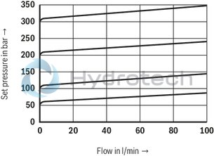
pE-qV characteristic curves
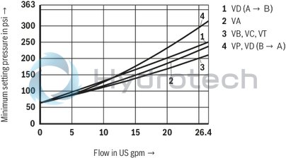
pE min-qV characteristic curves
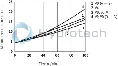
pE min-qV characteristic curves
Notice:
The characteristic curves apply to the pressure at the valve output p = 0 bar across the entire flow range.
Type ZDB 10 VA…
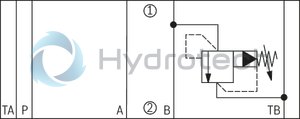
Type ZDB 10 VB…
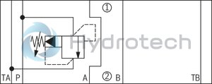
Type ZDB 10 VP…
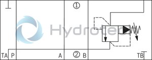
Type ZDB 10 VT…
Type Z2DB 10 VC…
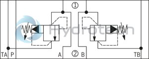
Type Z2DB 10 VD…
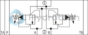
➀ = component side
➁ = plate side
Notice:
Deviating from ISO 4401, port T is referred to with TA and port T1 is referred to with TB in this data sheet.
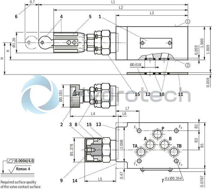
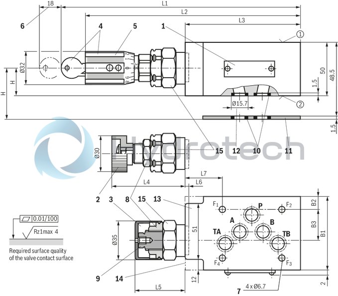
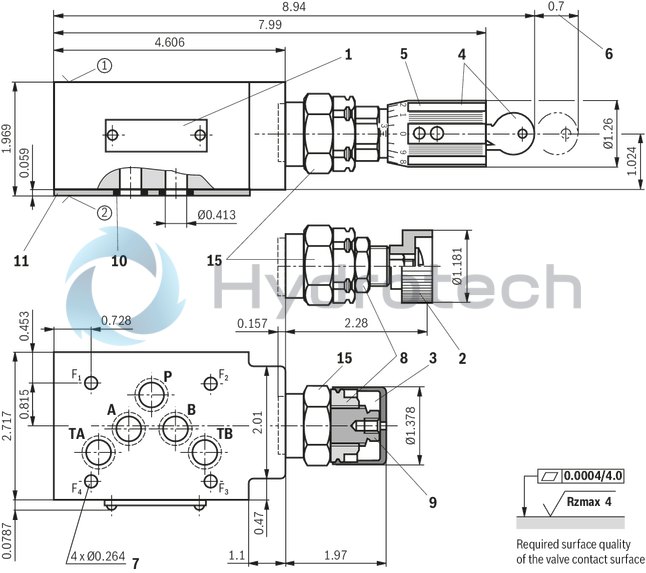
Version "VA", "VP" and "VT"
(dimensions im mm)
Dimensions in mm
|
1 |
Name plate |
|
2 |
Adjustment type "1" |
|
3 |
Adjustment type "2" (with version "J3" and "J5" without protective cap) |
|
4 |
Adjustment type "3" |
|
5 |
Adjustment type "7" |
|
6 |
Dimensions required to remove the key |
|
7 |
Valve mounting bores |
|
8 |
Lock nut SW24 |
|
9 |
Hexagon SW10 |
|
10 |
Identical seal rings for ports A, B, P, TA, TB (plate side) |
|
11 |
Sealing plate 80 x 70 x 1.5 mm (only with version “VA” and “VP”) |
|
12 |
Countersinks (only with version “VT”) |
|
13 |
Versions “VA” and “VP” |
|
14 |
Version “VT” |
|
15 |
Hexagon SW30, tightening torque MA = 50 Nm |
|
➀ |
component side – Porting pattern according to ISO 4401-05-04-0-05 |
|
➁ |
plate side – Porting pattern according to ISO 4401-05-04-0-05 |
|
Type |
B1 |
B2 |
B3 |
H |
L1 |
L2 |
L3 |
L4 |
L5 |
L6 |
L7 |
|
mm |
mm |
mm |
mm |
mm |
mm |
mm |
mm |
mm |
mm |
mm |
|
| VA/VP | 69 | 11.5 | 20.7 | 26 | 227 | 203 | 117 | 57.6 | 50.3 | 4 | 45.5 |
| VT | 70 | 12 | 27 | 25 | 218 | 194 | 105 | 60.9 | 53.6 | 0.7 | 32.5 |
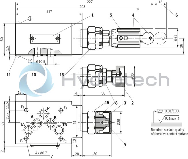
Version "VB"
(dimensions im mm)
Dimensions in mm
|
1 |
Name plate |
|
2 |
Adjustment type "1" |
|
3 |
Adjustment type "2" (with version "J3" and "J5" without protective cap) |
|
4 |
Adjustment type "3" |
|
5 |
Adjustment type "7" |
|
6 |
Dimensions required to remove the key |
|
7 |
Valve mounting bores |
|
8 |
Lock nut SW24 |
|
9 |
Hexagon SW10 |
|
10 |
Identical seal rings for ports A, B, P, TA, TB (plate side) |
|
11 |
Sealing plate 80 x 70 x 1.5 mm (only with version “VA” and “VP”) |
|
15 |
Hexagon SW30, tightening torque MA = 50 Nm |
|
➀ |
component side – Porting pattern according to ISO 4401-05-04-0-05 |
|
➁ |
plate side – Porting pattern according to ISO 4401-05-04-0-05 |
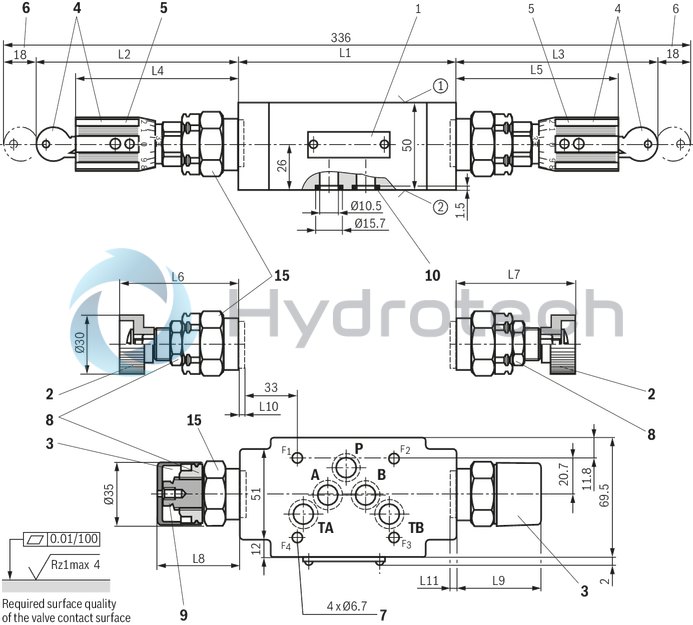
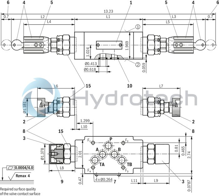
Version “VC” and “VD”
(dimensions in mm)
Dimensions in mm
|
1 |
Name plate |
|
2 |
Adjustment type "1" |
|
3 |
Adjustment type "2" (with version "J3" and "J5" without protective cap) |
|
4 |
Adjustment type "3" |
|
5 |
Adjustment type "7" |
|
6 |
Dimensions required to remove the key |
|
7 |
Valve mounting bores |
|
8 |
Lock nut SW24 |
|
9 |
Hexagon SW10 |
|
10 |
Identical seal rings for ports A, B, P, TA, TB (plate side) |
|
15 |
Hexagon SW30, tightening torque MA = 50 Nm |
|
➀ |
component side – Porting pattern according to ISO 4401-05-04-0-05 |
|
➁ |
plate side – Porting pattern according to ISO 4401-05-04-0-05 |
|
Type |
L1 |
L2 |
L3 |
L4 |
L5 |
L6 |
L7 |
L8 |
L9 |
L10 |
L11 |
|
mm |
mm |
mm |
mm |
mm |
mm |
mm |
mm |
mm |
mm |
mm |
|
| VC | 123 | 111 | 112 | 89 | 90 | 59 | 60 | 52 | 53 | 2 | 1 |
| VD | 132 | 107 | 112 | 85 | 90 | 56 | 56 | 49 | 49 | 6 | 6 |
Notices:
To port X and Y bored according to ISO 4401-05-05-0-05 (e.g. for pilot-operated directional valve NG10), version “SO30“ applies at the end of the ordering code! Deviating from ISO 4401, port T is referred to with TA and port T1 is referred to with TB in this data sheet.
Valve mounting screws (separate order)
Version "J3"4 hexagon socket head cap screws ISO 4762 - M6 - 10.9-CM-Fe-ZnNi-5-Cn-T0-H-B
friction coefficient µtotal = 0,09 … 0.14
Version "J5"
4 hexagon socket head cap screws ISO 4762 - M6 - 10.9-CM-Fe-ZnNi-8-Cn-T0-H-B
Friction coefficient µtotal = 0,09 … 0.14
Without corrosion protection
4 hexagon socket head cap screws ISO 4762 - M6 - 10.9
Friction coefficient µtotal = 0.12 … 0.17
Notice:
Length and tightening torque of the valve mounting screws must be calculated according to the components mounted under and over the sandwich plate valve.
Type Z2DB 10 VC and VD
Dimensions in mm
| 1) | Fit |
Type ZDB 10 VA, VP and VT
Dimensions in mm
| 1) | Fit |
Type ZDB 10 VA, VP and VT
Dimensions in mm