
BOSCH REXROTH
R900594742
Check Valves
Check valves: SV,SL 6.-6x/
BOSCH REXROTH
MATERIAL: R900594742
SUMMARY: Check valves: SV,SL 6.-6x/
Quantity in stock: 0
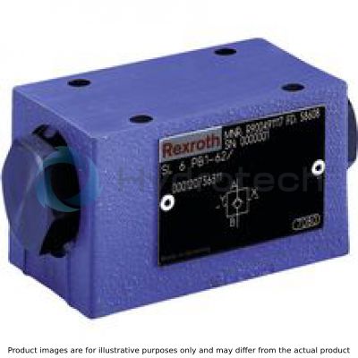
The isolator valve type SV is a releasable check valve for subplate mounting. It is used for the leakage-free blocking of one actuator port, also in case of longer standstill times.
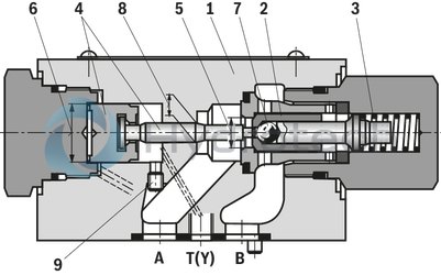
The valve basically consists of a housing (1), a seat poppet (2), a compression spring (3), a control spool (4) as well as of a pre-opening as ball seat valve (7), which is optional.
The seat valve can be flown through from direction A to B without external pilot pressure.
Condition: pA > pB + cracking pressure (compression spring). In the opposite direction, the seat valve closes hydraulically tight.
A sufficiently high pilot pressure at port X moves the control spool (4) in the direction of the seat valve and pushes the seat poppet (2) out of its seat. This allows for a free flow in both directions (active keeping open).
In order to ensure that the seat valve actively opens, the pressure ratios on both sides of the control spool (4) are just as important as the area ratios at the seat poppet (2) or (7).
This results in the following available options for the types
SV (large spool face A2 (6) connected to pA ) oras well as for the versions with pre-opening "A" and without pre-opening "B".
Version "A" (with pre-opening)
This valve is provided with an additional pre-opening. By pressurization at port X, the control spool (4) is moved to the right. As a result, the ball (7) is pushed off the seat first and the seat poppet (2) afterwards.
Notes!
Version "A":
The two-stage set-up with an increased control open ratio means even low pilot pressure can be unloaded securely. Avoidance of switching shocks due to dampened decompression of the pressure volume on the actuator side.Version "B":
In case of valves without pre-opening, the included pressure volume may be unloaded suddenly. Resulting switching shocks may lead to premature wear on installed components, as well as noise formation.
The modification of type SV to type SL is possible by exchange of plugs (9) and (10). One of the both plugs must always be installed!
Type SL 6 PB.‑6X/…
|
Type |
Plug (9) |
Plug (10) |
|
SL |
M3 (closed) |
M6 x 1 (open) |
|
01 |
02 |
03 |
04 |
05 |
06 |
07 |
08 |
09 |
10 |
||
|
S |
L |
6 |
P |
– |
6X |
/ |
* |
|
01 |
S |
|
|
02 |
Pilot oil return, external |
L |
|
03 |
Size 6 |
6 |
|
04 |
For subplate mounting |
P |
|
05 |
With pre-opening |
A |
|
Without pre-opening |
B |
|
|
Cracking pressure |
||
|
06 |
See characteristic curves |
1 |
|
2 |
||
|
3 |
||
|
4 1) |
||
|
07 |
Component series 60 … 69 (60 … 69: unchanged installation and connection dimensions) |
6X |
|
Corrosion resistance (outside) |
||
|
08 |
Without |
no code |
|
Galvanic coating DIN 50979 - Fe//Zn8//Cn//T0 (thick film passivation) |
J50 |
|
|
Seal material 2) |
||
|
09 |
NBR seals |
no code |
|
FKM seals |
V |
|
|
Other seals on request |
||
|
10 |
Further details in the plain text |
* |
1) Only version "B"
2) The selection of the seal material depends on the operating parameters (fluid, temperature, etc.)
general
|
Size |
6 | ||
|
Weight |
kg |
0.8 | |
|
Installation position |
any | ||
|
Ambient temperature range |
NBR seals |
°C |
-30 … +80 |
|
FKM seals |
°C |
-20 … +80 | |
|
MTTFD values according to EN ISO 13849 |
Years |
150 1) | |
| 1) | For further details, see data sheet 08012 |
hydraulic
|
Size |
6 | ||
|
Maximum operating pressure |
bar |
315 | |
|
Cracking pressure 1) |
bar |
1.5 / 3 / 6 / 10 | |
|
Maximum flow |
l/min |
60 | |
|
Direction of flow |
see symbols | ||
|
Hydraulic fluid |
see table | ||
|
Minimum pilot pressure |
bar |
5 | |
|
Maximum pilot pressure |
bar |
315 | |
|
Hydraulic fluid temperature range (NBR seals) |
°C |
-30 … +80 | |
|
Hydraulic fluid temperature range (FKM seals) |
°C |
-20 … +80 | |
|
Viscosity range |
mm²/s |
2.8 … 500 | |
|
Maximum admissible degree of contamination of the hydraulic fluid 2) |
Class 20/18/15 according to ISO 4406 (c) | ||
|
Pilot volume |
Port X |
cm³ |
0.68 |
|
Port Y |
cm³ |
0.58 | |
|
Area ratio |
Without pre-opening |
A1/A2 ~ 1/3; A4/A2 ~ 1/7 (see sectional drawing) | |
|
With pre-opening |
A3/A2 ~ 1/13 (see sectional drawing) | ||
| 1) | in free direction |
| 2) | The cleanliness classes specified for the components must be adhered to in hydraulic systems. Effective filtration prevents faults and simultaneously increases the life cycle of the components. For the selection of the filters, see www.boschrexroth.com/filter. |
For applications outside these parameters, please consult us!
|
Hydraulic fluid |
Classification |
Suitable sealing materials |
Standards |
|
|
Mineral oils and related hydrocarbons |
HL, HLP, HVLP |
NBR, FKM |
DIN 51524 |
|
|
Environmentally compatible |
Insoluble in water |
HEES |
NBR, FKM |
ISO 15380 |
|
HEPR |
FKM |
|||
|
Soluble in water |
HEPG |
FKM |
ISO 15380 |
|
|
Flame-resistant |
Water-free |
HFDU, HFDR |
FKM |
ISO 12922 |
|
Containing water |
HFC |
NBR |
ISO 12922 |
|
|
Important information on hydraulic fluids! For further information and data on the use of other hydraulic fluids please contact us! There may be limitations regarding the technical valve data (temperature, pressure range, life cycle, maintenance intervals, etc.)! |
||||
|
pA* |
Type-dependent (for type SL: pA* = 0) |
|
pSt |
Pilot pressure |
|
pA |
Working pressure in A |
|
pB |
Working pressure in B |
|
pF |
Cracking pressure (spring) |
|
A1 – A4 |
For areas, see sectional drawing and control area ratios |
Δp-qV characteristic curves
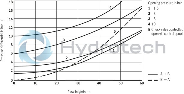

Calculation of the pilot pressure pSt dependent on pA and pB
(measured with HLP46, ϑOil = 40 ±5 °C)
Version "A" (with pre-opening)
Balance of forces:

Assumption: pA = 0

Version "B" (without pre-opening)
Balance of forces:

Assumption: pA = 0
Pilot oil return, external

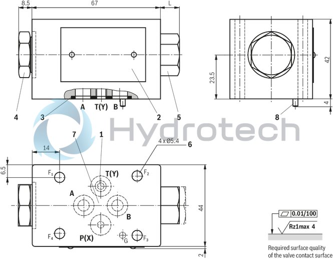
Dimensions in mm
|
L in mm |
||
|
Version |
without pre-opening "B" |
with pre-opening "A" |
|
„1“ , „2“ , „3“ |
11 |
21,5 |
|
„4“ |
14 |
– |
|
1 |
Port Y (M6 x 1; closed for type SV) |
|
2 |
Name plate |
|
3 |
Identical seal rings for ports A, B, P(X), (T)Y |
|
4 |
Plug screw SW24 (pilot spool), tightening torque MA = 80+5 Nm |
|
5 |
Plug screw SW22 (check valve uses), tightening torque MA = 25+5 Nm |
|
6 |
Through hole for valve mounting screws |
|
7 |
Porting pattern according to ISO 4401-03-02-0-05 and ISO 5781-03-04-0-00(with locating hole and locking pin ISO 8752-3x8-St) |
|
8 |
Locking pin ISO 8752-3x8-St |
Valve mounting screws (separate order)
4 hexagon socket head cap screws ISO 4762 - M5 x 50 - 10.9
(with friction coefficient μtotal = 0.14);
tightening torque MA = [si]8.9 Nm[/si][/imp]6.6 lb-ft[/imp] ± 10%
(please adjust in case of modified surfaces; use manual torque wrench!)