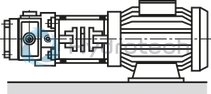
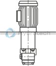
BOSCH REXROTH
PV7-1X/16-20RE01MC5-16WH
R900926429
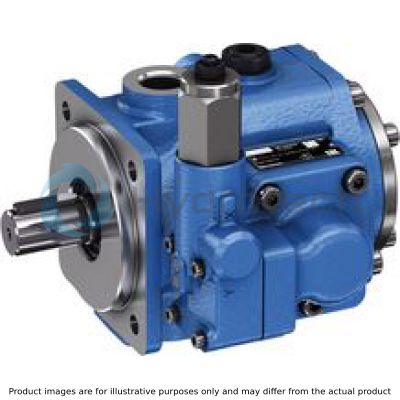
Vane Pumps
Variable vane pumps: PV7-1x/16
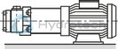
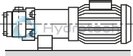
BOSCH REXROTH
MATERIAL: R900926429
SUMMARY: Variable vane pumps: PV7-1x/16
Quantity in stock: 0
Thanks to their specific design, type PV7... vane pumps with adjustable displacement boast a low flow pulsation and achieve very high repetition accuracy with low pressure peaks during the down control. The noise optimization achieved by adjusting the height adjustment screw provides for a low operating noise. Hydrodynamically lubricated plain bearings ensure a long life cycle. The axial compensation of the displacer provides optimum volumetric efficiency.
Design
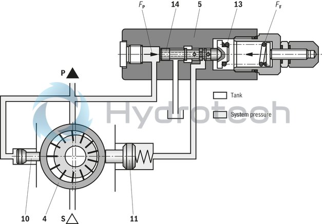
Hydraulic pumps of type PV7 are vane pumps with variable displacement.
They basically consist of housing (1), rotor (2), vanes (3), statorring (4), pressure controller (5) and adjustment screw (6).
The circular stator ring (4) is retained by the small reciprocating control piston (10) and the large reciprocating control piston (11). The third supporting point of the ring is height adjustment screw (7).
The driven rotor (2) rotates within stator ring (4). The vanes guided within the rotor are pressed against stator ring (4) by centrifugal force.
Adjustment
As pressure builds up in the system, the rear side of the small control piston (10) is always pressurised to system pressure via a channel.
In the displacement position, the rear side of the large control piston(11) is also pressurised to system pressure via a bore in control spool (14). Control piston (11) with the larger area holds stator ring (4) in its eccentric position.
The pump displaces fluid at a pressure below the zero stroke pressure set on pressure controller (5).
Control spool (14) is held by spring (13) in a certain position.
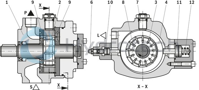
Suction and displacement procedure
The cells required for the transport of the fluid (8) are built by the vanes (3), rotor (2) and stator ring (4) and the control plate (9).
To safeguard the pump function during commissioning, the stator ring (4) is kept by the spring (12) behind the big actuating piston (11) in its eccentric position (displacer position).
The cell volume (8) increases by the rotation of the rotor (2) and via the suction channel (S), the cells are filled with hydraulic fluid. When reaching the biggest cell volume, the cells (8) are separated from the suction side. If the rotor (2) is rotated further, connection to the pressure side is established, the cells narrow and press the fluid via the pressure channel (P) into the system.
Down control
If the force FP, resulting from the product pressure x area, exceeds the counterforce FF of the spring, the regulator spool(14) is shifted to the spring (13). Thus, the chamber behind the big actuating piston (11) is connected with the tank and thus unloaded.
The small actuating piston (10) which is continuously pressurized with system pressure, moves the stator ring (4) nearly to the central position. The pump maintains the pressure, the flow declines to zero and the leakages are replaced.
Power loss and heating of the fluid are kept to a minimum.
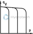
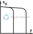
The characteristic curve qV-p is vertical and moves in parallel when setting different pressure values.
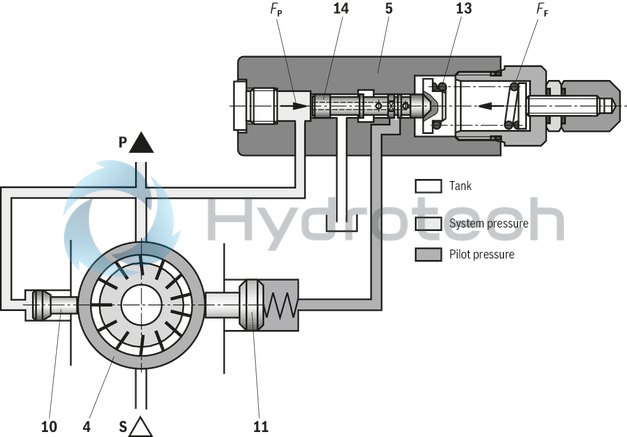
On-stroke control
When the pressure in the system falls below the set zero stroke pressure, spring (13) pushes control spool (14) back to its original position.
The large control piston (11) is again pressurised and shifts stator ring (4) to an eccentric position. The pump starts to displace again.
|
01 |
02 |
03 |
04 |
05 |
06 |
07 |
08 |
09 |
10 |
11 |
|||
|
PV7 |
– |
1X |
/ |
R |
E |
M |
– |
|
Type |
|||
|
01 |
Adjustable vane pump, pilot operated |
PV7 |
|
|
Component series |
|||
|
02 |
Component series 10 ... 19 (10 ... 19: unchanged installation and connection dimensions) |
1X |
|
|
Frame size-size |
|||
|
03 |
BG 10 - NG 14 cm3 |
10-14 |
|
|
BG 10 - NG 20 cm3 |
10-20 |
||
|
BG 16 - NG 20 cm3 |
16-20 |
||
|
BG 16 - NG 30 cm3 |
16-30 |
||
|
BG 25 - NG 30 cm3 |
25-30 |
||
|
BG 25 - NG 45 cm3 |
25-45 |
||
|
BG 40 - NG 45 cm3 |
40-45 |
||
|
BG 40 - NG 71 cm3 |
40-71 |
||
|
BG 63 - NG 71 cm3 |
63-71 |
||
|
BG 63 - NG 94 cm3 |
63-94 |
||
|
BG 100 - NG 118 cm3 |
100-118 |
||
|
BG 100 - NG 150 cm3 |
100-150 |
||
|
Direction of rotation |
|||
|
04 |
clockwise |
R |
|
|
Shaft end version |
|||
|
05 |
Cylindrical drive shaft with output |
E |
|
|
Line connection |
|||
|
06 |
BG10, 16, 25: Suction and pressure port: Pipe thread |
01 |
|
|
BG40: Suction port: SAE flange connection Pressure connection: Pipe thread |
37 |
||
|
BG63, 100: Suction and pressure port: SAE flange connection |
07 |
||
|
Seal material |
|||
|
07 |
NBR seals |
M |
|
|
Controller type |
|||
|
08 |
Pressure controller |
C |
|
|
Pressure controller for hydraulic remote pressure adjustment |
D |
||
|
Flow controller |
N |
||
|
Pressure controller with electric 2-step pressure adjustment |
W |
||
|
Controller option |
|||
|
09 |
Standard |
0 |
|
|
lockable |
3 |
||
|
with K plate |
5 |
||
|
with Q plate |
6 |
||
|
lockable with K plate |
7 |
||
|
lockable with Q plate |
8 |
||
|
Zero stroke pressure range |
|||
|
10 |
BG 10 - NG 14 cm3 |
up to 160 bar |
16 |
|
BG 10 - NG 20 cm3 |
up to 100 bar |
10 |
|
|
BG 16 - NG 20 cm3 |
up to 160 bar |
16 |
|
|
BG 16 - NG 30 cm3 |
up to 80 bar |
08 |
|
|
BG 25 - NG 30 cm3 |
up to 160 bar |
16 |
|
|
BG 25 - NG 45 cm3 |
up to 80 bar |
08 |
|
|
BG 40 - NG 45 cm3 |
up to 160 bar |
16 |
|
|
BG 40 - NG 71 cm3 |
up to 80 bar |
08 |
|
|
BG 63 - NG 71 cm3 |
up to 160 bar |
16 |
|
|
BG 63 - NG 94 cm3 |
up to 80 bar |
08 |
|
|
BG 100 - NG 118 cm3 |
up to 160 bar |
16 |
|
|
BG 100 - NG 150 cm3 |
up to 80 bar |
08 |
|
|
Directional valve |
|||
|
11 |
Normally closed |
WG 1) |
|
|
Normally open |
WH 1) |
||
| 1) | only for C5, D5 and W controller (optional) |
Pump with customer-specific setting:
When ordering, please indicate the setting data in plain text (e.g. qVmax = 20 l/min; pZero stroke = 70 bar). The pump will be set to the desired values and the operating noise is optimized accordingly.
Without a plain text indication, the flow and the zero stroke pressure are set to the respective maximum values and the operating noise is optimized at these maximum values.
Combination options
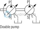
All pumps of type PV7 can be combined. Each pump with Eshaft is provided with an output spline.
All combinations of a PV7 + optional rear pump are sealed against each other by means of the shaft seal ring of the rear pump. The seal is direction-related. In the case of more stringent requirements with regard to a reliable separation of media, please consult the technical sales department.
Possible combinations and the material no. of the required combination parts can be found in the following table.
|
Back pump |
Front pump |
|||
|
PV7-1X/10 |
PV7-1X/16/25 |
PV7-1X/40/63 |
PV7-1X/100 |
|
|
PV7-1X/06-...RA01M... |
R900540811 |
R900540812 |
R900540814 |
R900543034 |
|
PV7-1X/10-...RE01M... |
R900540811 |
R900540812 |
R900540814 |
R900543034 |
|
PV7-1X/16-...RE01M... |
– |
R900540813 |
R900540815 |
R900543035 |
|
PV7-2X/20-...RA01M... |
– |
R900540813 |
R900540815 |
R900543035 |
|
PV7-1X/25-...RE01M... |
– |
R900540813 |
R900540815 |
R900543035 |
|
PV7-1X/40-...RE37M... |
– |
– |
R900540816 |
R900543036 |
|
PV7-1X/63-...RE07M... |
– |
– |
R900540816 |
R900543036 |
|
PV7-1X/100-...RE07M... |
– |
– |
– |
R900543037 |
|
PGF1-2X/...RE01VU2 |
R900857584 |
R900857585 |
– |
– |
|
PGF2-2X/...RJ...VU2 |
R900541209 |
R900541210 |
R900541203 |
R900544959 |
|
PGF3-3X/...RJ...VU2 |
– |
R900888267 |
R900880623 |
R900880624 |
|
PGP2-2X/...RJ20VU2 |
R900541209 |
R900541210 |
R900541203 |
R900544959 |
|
PGP3-3X/...RJ...VU2 |
– |
R900888267 |
R900880623 |
R900880624 |
|
PGH2-2X/...RR...VU2 |
R900541209 |
R900541210 |
R900541203 |
R900544959 |
|
PGH3-2X/...RR...VU2 |
R900541209 |
R900541210 |
R900541203 |
R900544959 |
|
PGH4-2X/...RR...VU2 |
– |
– |
R900876578 |
R900876576 |
|
PVV/Q1/2-1X/...RJ15... |
– |
R900888267 |
R900880623 |
R900880624 |
|
PVV/Q4/5-1X/...RJ15... |
– |
– |
R900876023 |
R900875983 |
|
AZPF..... |
R900541209 |
R900541210 |
R900541203 |
R900544959 |
|
PR4-1X/0,40...2,00-...WG... |
R900541204 |
R900541205 |
R900541206 |
– |
|
PR4-3X/1,60...20,00-...RG... |
R900541214 |
– |
– |
– |
|
PR4-3X/1,60...20,00-...RA... |
– |
R900541207 |
R900541208 |
R900543767 |
|
A10VSO10...U |
R900541209 |
R900541210 |
R900541203 |
R900544959 |
|
A10VSO18...U |
R900541209 |
R900541210 |
R900541203 |
R900544959 |
|
A10VO28...S |
– |
R900888267 |
R900880623 |
R900880624 |
Ordering codes of multiple pumps
|
01 |
02 |
03 |
04 |
05 |
06 |
07 |
08 |
09 |
10 |
11 |
12 |
13 |
14 |
||||
|
P2 |
V7 |
/ |
100-150 |
C0 |
+ |
V7 |
/ |
100-150 |
C0 |
R |
E |
07 |
+ |
07 |
E4 |
* |
|
1 |
2-fold |
P2 |
|
2 |
Series of the first pump |
V7 |
|
3 |
Size of the first pump |
100-150 |
|
4 |
Controller of the first pump |
C0 |
|
5 |
Series of the second pump |
V7 |
|
6 |
Size of the second pump |
100-150 |
|
7 |
Controller of the second pump |
C0 |
|
8 |
Direction of rotation |
R |
|
9 |
Shaft version of the first pump |
E |
|
10 |
Pipe connection of the first pump |
07 |
|
11 |
Shaft version of the secondpump (if required) 1) |
|
|
12 |
Line connection of the second pump |
07 |
|
13 |
Mounting flange of the first pump |
E4 |
|
14 |
Further details in the plain text |
* |
| 1) |
With PGF2 and PGF3 Triple and quadruple pumps are coded by analogy! |
|
Frame size |
|
10 | 16 | 25 | 40 | 63 | 100 | ||||||||
|
Size |
|
14 | 20 | 20 | 30 | 30 | 45 | 45 | 71 | 71 | 94 | 118 | 150 | ||
|
Component series |
|
1X | |||||||||||||
|
Mounting type |
|
4-hole flange according to VDMA 24560 part 1 and ISO 3019/2 | |||||||||||||
|
Line connections |
|
Pipe thread or SAE flange connection (depending on frame size) | |||||||||||||
|
Installation position |
|
any, preferably horizontal | |||||||||||||
|
Shaft load |
|
Radial and axial forces cannot be transmitted | |||||||||||||
|
Direction of rotation |
|
Clockwise rotation (looking at the shaft end) | |||||||||||||
|
Drive speed |
n |
rpm |
900 ... 1,800 | ||||||||||||
|
Displacement |
Vg |
cm³ |
14 | 20 | 20 | 30 | 30 | 45 | 45 | 71 | 71 | 94 | 118 | 150 | |
|
Admissible drive torque |
Tmax |
Nm |
90 | 140 | 180 | 280 | 440 | 680 | |||||||
|
Flow, max. 1) |
qV |
l/min |
21 | 29 | 43.5 | 66 | 104 | 108 | 136 | 171 | 218 | ||||
|
Leakage flow in the zero stroke 2) |
qVL |
l/min |
2.7 | 1.9 | 4 | 2.5 | 5.3 | 3.2 | 6.5 | 4 | 8 | 5.3 | 11 | 7.3 | |
|
Operating pressure, absolute |
Inlet |
pmin-max |
bar |
0.8 ... 2.5 | |||||||||||
|
Outlet 3) |
pmax |
bar |
160 | 100 | 160 | 80 | 160 | 80 | 160 | 80 | 160 | 80 | 160 | 80 | |
|
Leakage output |
pmax |
bar |
2 | ||||||||||||
|
Mass 4) |
m |
kg |
12.5 | 17 | 21 | 30 | 37 | 56 | |||||||
|
Change in flow 5) |
qV |
l/min |
10 | 14 | 18 | 25 | 34 | 46 | |||||||
| 1) |
Due to production tolerances, the flow may exceed the specified values by approx. 6% (measured at n = 1450 rpm; p = 10 bar; v = 41 mm2/s |
| 2) | With operating pressure output = pmax |
| 3) | The minimum adjustable pressure lies at approx. 20 bar, in the plant, 30 bar are set by default |
| 4) | With pressure controller |
| 5) | With one rotation of the set screw and n = 1450 rpm |
Hydraulic fluid
|
Permissible hydraulic fluid 1) |
Mineral oil (HLP) to DIN 51524-2 | ||
|
Special fluid 2) 3) |
HETG and HEES hydraulic fluids according to VDMA 24568 Mineral oil (HLP) according to DIN 51524-2 (from 100 mm2/s Mineral oil (HL) to DIN 51524-1 |
||
|
Hydraulic fluid temperature range 4) |
°C |
-10 … +70 | |
|
Viscosity range |
mm²/s |
16 … 160 | |
|
Admissible start viscosity |
mm²/s |
800 5) 6) 200 5) 6) |
800 |
|
Maximum admissible degree of contamination of the hydraulic fluid 7) |
Class 20/18/15 according to ISO 4406 (c) | ||
| 1) | In case of use up to 160 bar (nominal pressure) |
| 2) | up to operating pressure pmax = 100 bar |
| 3) | up to operating pressure pmax = 80 bar |
| 4) | Observe the admissible viscosity range! |
| 5) | in case of start-up in delivery operation |
| 6) | in case of start-up in zero stroke operation |
| 7) | The cleanliness classes specified for the components must be adhered to in hydraulic systems. Effective filtration prevents faults and simultaneously increases the life cycle of the components. For the selection of the filters, see www.boschrexroth.com/filter. |
For applications outside these parameters, please consult us!
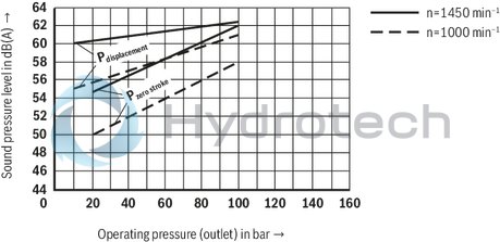
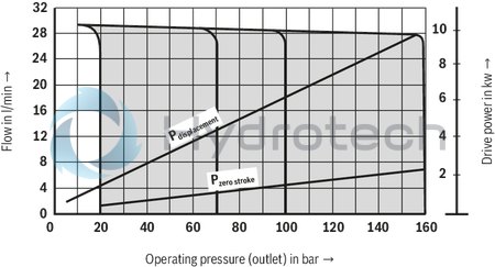
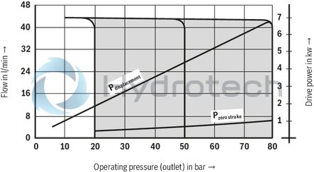
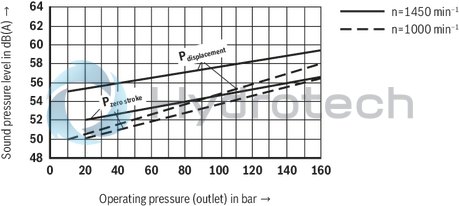
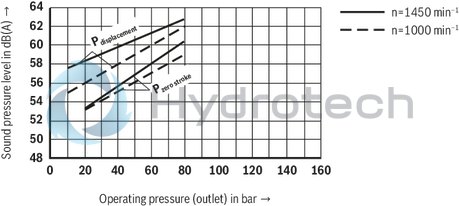
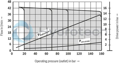
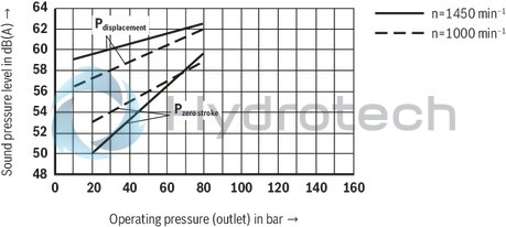
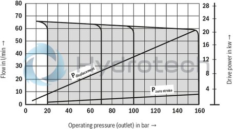
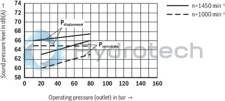
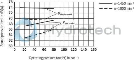
(measured at n = 1450 min-1; ν = 41 mm2/s; ϑ = 50 °C)
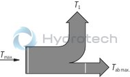
PV7/10-14
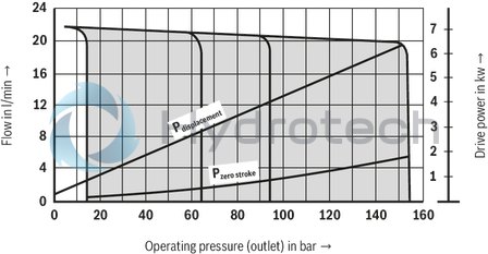
PV7/10-20
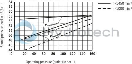
Sound pressure level measured in the anechoic chamber according to DIN 45635 part 26. Distance between microphone – pump = 1 m.
Please take this into account for the order!
The pump setting is selected so that the most favourable sound pressure level is obtained at the relevant highest zero stroke pressure. It is therefore essential to specify the required zero stroke pressure on the order, unless it corresponds to the nominal pressure.
Observe engineering notes.
PV7/10-14
PV7/10-20
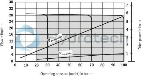
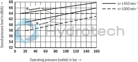
(measured at n = 1450 min-1; ν = 41 mm2/s; ϑ = 50 °C)
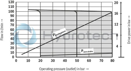
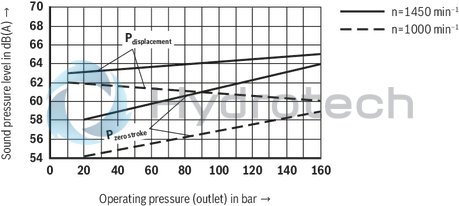
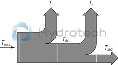
PV7/16-20
PV7/16-30
Sound pressure level measured in the anechoic chamber according to DIN 45635 part 26. Distance between microphone – pump = 1 m.
Please take this into account for the order!
The pump setting is selected so that the most favourable sound pressure level is obtained at the relevant highest zero stroke pressure. It is therefore essential to specify the required zero stroke pressure on the order, unless it corresponds to the nominal pressure.
Observe engineering notes.
PV7/16-20
PV7/16-30
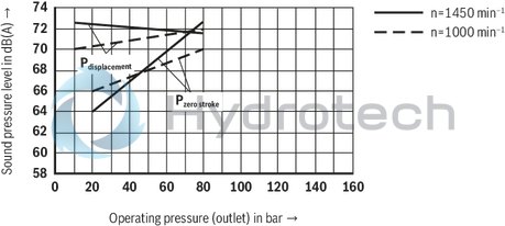
(measured at n = 1450 min-1; ν = 41 mm2/s; ϑ = 50 °C)
PV7/25-30
PV7/25-45
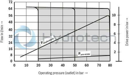
Sound pressure level measured in the anechoic chamber according to DIN 45635 part 26. Distance between microphone – pump = 1 m.
Please take this into account for the order!
The pump setting is selected so that the most favourable sound pressure level is obtained at the relevant highest zero stroke pressure. It is therefore essential to specify the required zero stroke pressure on the order, unless it corresponds to the nominal pressure.
Observe engineering notes.
PV7/25-30
PV7/25-45
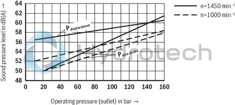
(measured at n = 1450 min-1; ν = 41 mm2/s; ϑ = 50 °C)
PV7/40-45
PV7/40-71
Sound pressure level measured in the anechoic chamber according to DIN 45635 part 26. Distance between microphone – pump = 1 m.
Please take this into account for the order!
The pump setting is selected so that the most favourable sound pressure level is obtained at the relevant highest zero stroke pressure. It is therefore essential to specify the required zero stroke pressure on the order, unless it corresponds to the nominal pressure.
Observe engineering notes.
PV7/40-45
PV7/40-71
(measured at n = 1450 min-1; ν = 41 mm2/s; ϑ = 50 °C)
PV7/63-71
PV7/63-94

Sound pressure level measured in the anechoic chamber according to DIN 45635 part 26. Distance between microphone – pump = 1 m.
Please take this into account for the order!
The pump setting is selected so that the most favourable sound pressure level is obtained at the relevant highest zero stroke pressure. It is therefore essential to specify the required zero stroke pressure on the order, unless it corresponds to the nominal pressure.
Observe engineering notes.
PV7/63-71
PV7/63-94
(measured at n = 1450 min-1; ν = 41 mm2/s; ϑ = 50 °C)
PV7/100-118
PV7/100-150
PV7/100-150
Sound pressure level measured in the anechoic chamber according to DIN 45635 part 26. Distance between microphone – pump = 1 m.
Please take this into account for the order!
The pump setting is selected so that the most favourable sound pressure level is obtained at the relevant highest zero stroke pressure. It is therefore essential to specify the required zero stroke pressure on the order, unless it corresponds to the nominal pressure.
Observe engineering notes.
PV7/100-118
PV7/100-150
Controller programme
C controller
Pressure controller
with mechanical pressure adjustment, ordering code ...C0-... (in lockable version, ordering code ...C3-...)
Symbol
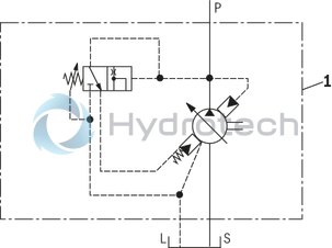
|
1 |
Pump: PV7-1X/… |
D controller
Pressure controller
with hydraulic pressure remote control, ordering code ...D0-... (in lockable version, ordering code ...D3-...)
Symbol
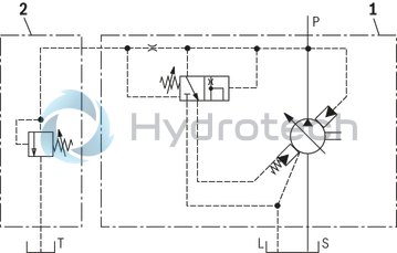
|
1 |
Pump: PV7-1X/… |
|
2 |
Pressure relief valve |
N controller
Flow controller
with mechanical flow adjustment, ordering code ...N0-... (in lockable version, ordering code ...N3-...)

Symbol
|
1 |
Pump: PV7-1X/… |
|
2 |
Metering orifice |
|
3 |
Pressure relief valve |
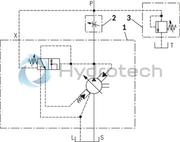
W controller
Pressure controller
with electrically switchable 2-stage pressure adjustment element, ordering code ...W0-...
Symbol
|
1 |
Pump: PV7-1X/… |
|
2.1 |
3/2 directional cartrdige valve |
|
2.2 |
Pressure relief valve Typ DBD… |
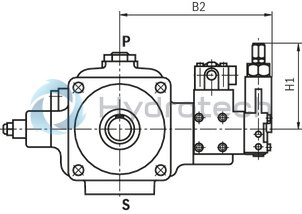
Unit dimensions
W controller
For further unit dimensions, see Dimensions
Dimensions in mm
|
FS |
B1 |
H1 |
H2 |
|
mm |
mm |
mm |
|
|
10 |
189 |
187,5 |
77,5 |
|
16 |
192 |
189 |
79 |
|
25 |
198 |
189 |
79 |
|
40 |
224 |
188,5 |
8,5 |
|
63 |
229 |
188,5 |
8,5 |
|
100 |
248,5 |
188,5 |
78,5 |
Hydraulic start-up aid (K plate)
Sandwich plate
with valve for unloading when starting up at the smallest zero stroke pressure.
Zero stroke pressure approx. 20 bar (depending on the application)
Ordering code: ...5-...
(in lockable version, ordering code ...7-...)
Notice
Not suitable for 2 stage regulation!
Symbol
|
1 |
Pump: PV7-1X/… |
|
2 |
3/2 directional cartrdige valve |
|
3 |
C, D or N controller |
Unit dimensions
K plate
For further unit dimensions, see Dimensions
Dimensions in mm
|
Frame size |
B2 |
B7 |
H1 |
|
mm |
mm |
mm |
|
|
10 |
204,5 |
143,5 |
117 |
|
16 |
207,5 |
146,5 |
118 |
|
25 |
214 |
153 |
118 |
|
40 |
240 |
179 |
118 |
|
63 |
244,5 |
183,5 |
118 |
|
100 |
264 |
203 |
118 |
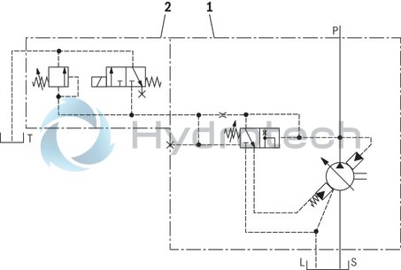
Flow/pressure controller (Q plate)
Sandwich pump
For combining a flow controller with a pressure-compensated pump With built-on standard flow controllerOrdering code: ...6-...
(in lockable version, ordering code ...8-...)
Symbol
|
1 |
Pump: PV7-1X/… |
|
2 |
Sandwich plate for combining the pressure controller and the flow controller function |
|
3 |
Flow controller |
|
4 |
Pressure controller |
|
5 |
Metering orifice |
Unit dimensions
Q plate
For further unit dimensions, see Dimensions
Dimensions in mm
|
Frame size |
B2 |
H1 |
|
mm |
mm |
|
|
10 |
173,5 |
117 |
|
16 |
176,5 |
118,5 |
|
25 |
182,5 |
118,5 |
|
40 |
208,5 |
118 |
|
63 |
213,5 |
118 |
|
100 |
233 |
118 |
Lock
Material no.: R900844598
This lock is included in the scope of supply for pumps with controller options of versions ...3..., ...7... or ...8...
Functional description
After unlocking (by turning the key clockwise) the complete lock cover can be removed from the controller, which allows free access to the adjustment element.
To lock, the lock cover must be placed over the controller adjustment element and pressed home, the lock cylinder pressed down and the key turned to the left.
The lock can be easily retrofitted to a standard pump.
Unscrew the cap nut from the controller adjustment element. Fit the cap nut that is provided with the key Plug on the lock as shown in the functional description.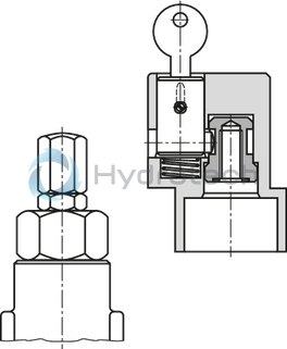

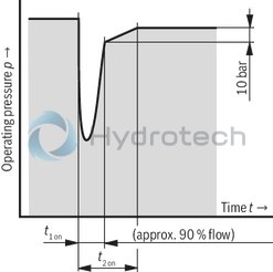
Dynamic characteristics of the pressure control
Test set-up
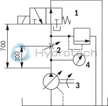
|
1 |
Directional valve (switching time duration 30 ms) |
|
2 |
Throttle for setting the pressure during displacement |
|
3 |
Hydraulic pump |
|
4 |
pressure tapping point |
Off-stroke control
qV displacement → qV zero stroke
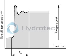
On-stroke control
qVzero stroke → qV displacement
|
Control times |
Off-stroke control time in ms (average values) |
On-stroke control time in ms (average values) |
||||||||||
|
qV displacement → qV zero stroke |
qVzero stroke → qV displacement |
|||||||||||
|
Frame sizes and sizes |
20 → 160 bar |
20 → 80 bar |
20 → 40 bar |
160 → 130 bar |
80 → 60 bar |
40 → 30 bar |
||||||
|
toff |
pmax 1) |
toff |
pmax |
toff |
pmax |
t1 up |
t2 up |
t1 up |
t2 up |
t1 up |
t2 up |
|
|
10-14 |
100 |
180 |
– |
– |
150 |
80 |
60 |
80 |
– |
– |
60 |
90 |
|
10-20 |
– |
– |
100 |
130 |
150 |
100 |
– |
– |
60 |
80 |
50 |
100 |
|
16-20 |
100 |
200 |
– |
– |
120 |
100 |
50 |
80 |
– |
– |
50 |
90 |
|
16-30 |
– |
– |
100 |
140 |
150 |
110 |
– |
– |
50 |
80 |
50 |
100 |
|
25-30 |
100 |
220 |
– |
– |
120 |
120 |
80 |
100 |
– |
– |
70 |
100 |
|
25-45 |
– |
– |
100 |
150 |
120 |
120 |
– |
– |
80 |
100 |
80 |
130 |
|
40-45 |
100 |
240 |
– |
– |
120 |
140 |
70 |
100 |
– |
– |
60 |
100 |
|
40-71 |
– |
– |
100 |
180 |
120 |
150 |
– |
– |
80 |
100 |
80 |
140 |
|
63-71 |
100 |
2202 |
– |
– |
150 |
180 |
80 |
120 |
– |
– |
100 |
140 |
|
63-94 |
– |
– |
100 |
1502 |
220 |
150 |
– |
– |
120 |
150 |
130 |
210 |
|
100-118 |
100 |
2202 |
– |
– |
250 |
200 |
100 |
150 |
– |
– |
150 |
250 |
|
100-150 |
– |
– |
100 |
1502 |
280 |
150 |
– |
– |
150 |
200 |
180 |
280 |
| 1) | Admissible pressure peaks |
| 2) | Pressure relief valve for limitation of the pressure peaks required |
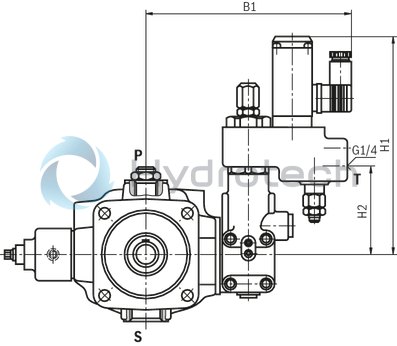
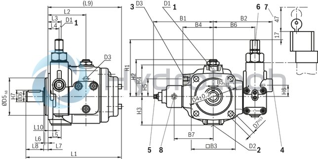
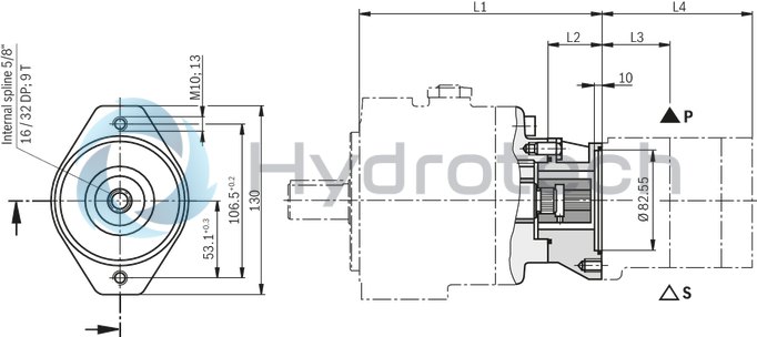
Single pump with C, D and N controller
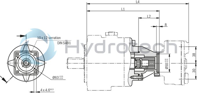
Dimensions in mm
|
1 |
Pressure port 1) |
|
2 |
Suction port 2) |
|
3 |
Leakage port |
|
4 |
In the case of a controller for hydraulic pressure remote control |
|
5 |
Flow adjustment Note on the adjustment: Turning clockwise: Reduction of the flow Turning counter-clockwise: Increase in the flow The set flow should not be less than 50 % of the maximum value |
|
6 |
Pressure adjustment Note on the adjustment: Turning clockwise: Increase in operating pressure Turning counter-clockwise: Reduction of the operating pressure
Note: The zero stroke pressure changes by approx. 19 bar with one turn of the adjustment screw. |
|
7 |
Space required to remove the lock cover (the pressure can only be adjusted when the lock cover is removed) |
|
8 |
Test point G1/4, 12 deep |
| 1) |
Frame sizes 10, 16, 25 and 40 Pipe thread “G...“ to ISO 228/1 Frame sizes 163 and 100, flange connection to SAE |
| 2) |
Frame sizes 110, 16 and 25 Pipe thread “G...“ to ISO 228/1 Frame sizes 140, 63 and 100, flange connection to SAE |
|
FS |
L1 |
L2 |
L3 |
L4 |
L5 |
L6 |
L7 |
L8 |
L9 |
L10 |
B1 |
B2 |
B3 |
B4 |
B5h9 |
B6 |
B7 |
|
mm |
mm |
mm |
mm |
mm |
mm |
mm |
mm |
mm |
mm |
mm |
mm |
mm |
mm |
mm |
mm |
mm |
|
|
10 |
193 |
78,5 |
26 |
22 |
26 |
7 |
8 |
36 |
149 |
9 |
130 |
125 |
96 |
65 |
6 |
90 |
88 |
|
16 |
217 |
86 |
37 |
20 |
37 |
9 |
10 |
42 |
165 |
10 |
134,5 |
131 |
120 |
69 |
8 |
93 |
92 |
|
25 |
229 |
86 |
34 |
20 |
38 |
9 |
10 |
42 |
177 |
10 |
140,7 |
137 |
120 |
75 |
8 |
99 |
98 |
|
40 |
254,6 |
86 |
26,5 |
21,5 |
43 |
9 |
10 |
58 |
186,6 |
12 |
157,8 |
161 |
141,2 |
94 |
10 |
125 |
115,5 |
|
63 |
279 |
99 |
39 |
34,5 |
51 |
9 |
10 |
58 |
211 |
13 |
163,7 |
165 |
141,2 |
100 |
10 |
130 |
121 |
|
100 |
334 |
111 |
45,5 |
28,5 |
60,5 |
9 |
10 |
82 |
242 |
16 |
191,7 |
184,5 |
200 |
121 |
12 |
149,5 |
150 |
|
FS |
H1 |
H2 |
H3 |
H4 |
H5 |
H6 |
H7 |
D11) |
D22) |
D3 |
D42±0,2 |
∅D5h8 |
∅D6 |
D7H13 |
|
mm |
mm |
mm |
mm |
mm |
mm |
mm |
mm |
mm |
mm |
mm |
||||
|
10 |
117 |
74 |
58 |
64 |
37 |
25 |
22,5 |
G1/2 |
G1 |
G1/4 |
103 |
80 |
20j6 |
9 |
|
16 |
118,5 |
81,5 |
68 |
72 |
40 |
26,5 |
28 |
G3/4 |
G1 1/4 |
G3/8 |
125 |
100 |
25j6 |
11 |
|
25 |
118,5 |
91,5 |
92 |
80 |
40 |
26,5 |
28 |
G1 |
G1 1/2 |
G3/8 |
125 |
100 |
25j6 |
11 |
|
40 |
118 |
105,5 |
89 |
94 |
45 |
26 |
35 |
G1 |
SAE1 1/2“ |
G1/2 |
160 |
125 |
32k6 |
14 |
|
63 |
118 |
111,5 |
105 |
100 |
47 |
26 |
35 |
SAE1 1/4“ |
SAE 2“ |
G1/2 |
160 |
125 |
32k6 |
14 |
|
100 |
118 |
123,5 |
126 |
111 |
52 |
26 |
43 |
SAE1 1/2“ |
SAE2 1/2“ |
G3/4 |
200 |
160 |
40k6 |
18 |
| 1) |
Frame sizes 10, 16, 25 and 40 Pipe thread “G...“ to ISO 228/1 Frame sizes 163 and 100, flange connection to SAE |
| 2) |
Frame sizes 110, 16 and 25 Pipe thread “G...“ to ISO 228/1 Frame sizes 140, 63 and 100, flange connection to SAE |
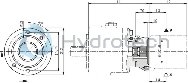
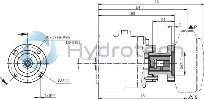
Pump combination P2V7... + V7/...
Dimensions in mm
|
1st pump FS |
2nd pump FS |
L1 |
L2 |
L3 |
ØD1 |
ØD2 |
ØD3 |
D4 |
H1 |
B1 |
L4 |
L5 |
L6 |
|
mm |
mm |
mm |
mm |
mm |
mm |
mm |
mm |
mm |
mm |
mm |
|||
|
10 |
06 |
182 |
50 |
8 |
80 |
103 |
20 |
M8 |
22,8 |
6 |
199 |
202,5 |
283 |
|
10 |
182 |
50 |
8 |
80 |
103 |
20 |
M8 |
22,8 |
6 |
208 |
208 |
331 |
|
|
16 |
06 |
200 |
55 |
8 |
80 |
103 |
20 |
M8 |
22,8 |
6 |
217 |
220,5 |
301 |
|
10 |
200 |
55 |
8 |
80 |
103 |
20 |
M8 |
22,8 |
6 |
226 |
226 |
349 |
|
|
16 |
208 |
63 |
10 |
100 |
125 |
25 |
M10 |
28,3 |
8 |
245 |
245 |
373 |
|
|
20 |
208 |
63 |
10 |
100 |
125 |
25 |
M10 |
28,3 |
8 |
238 |
233 |
343 |
|
|
25 |
06 |
212 |
55 |
8 |
80 |
103 |
20 |
M8 |
22,8 |
6 |
229 |
232,5 |
313 |
|
10 |
212 |
55 |
8 |
80 |
103 |
20 |
M8 |
22,8 |
6 |
238 |
238 |
361 |
|
|
16 |
220 |
63 |
10 |
100 |
125 |
25 |
M10 |
28,3 |
8 |
257 |
257 |
385 |
|
|
20 |
220 |
63 |
10 |
100 |
125 |
25 |
M10 |
28,3 |
8 |
245 |
245 |
354 |
|
|
25 |
220 |
63 |
10 |
100 |
125 |
25 |
M10 |
28,3 |
8 |
254 |
258 |
397 |
|
|
40 |
06 |
221,6 |
55 |
8 |
80 |
103 |
20 |
M8 |
22,8 |
6 |
238,6 |
242,1 |
322,6 |
|
10 |
221,6 |
55 |
8 |
80 |
103 |
20 |
M8 |
22,8 |
6 |
247,6 |
247,6 |
322,6 |
|
|
16 |
229,6 |
63 |
10 |
100 |
125 |
25 |
M10 |
28,3 |
8 |
266,6 |
266,6 |
394,6 |
|
|
20 |
229,6 |
63 |
10 |
100 |
125 |
25 |
M10 |
28,3 |
8 |
254,6 |
254,6 |
363,6 |
|
|
25 |
229,6 |
63 |
10 |
100 |
125 |
25 |
M10 |
28,3 |
8 |
263,6 |
267,6 |
406,6 |
|
|
40 |
246,6 |
80 |
10 |
125 |
160 |
32 |
M12 |
35,3 |
10 |
273,1 |
289,6 |
433,2 |
|
|
63 |
06 |
244,5 |
55 |
8 |
80 |
103 |
20 |
M8 |
22,8 |
6 |
261,5 |
265 |
345,5 |
|
10 |
244,5 |
55 |
8 |
80 |
103 |
20 |
M8 |
22,8 |
6 |
270,5 |
270,5 |
393,5 |
|
|
16 |
252,5 |
63 |
10 |
100 |
125 |
25 |
M10 |
28,3 |
8 |
289,5 |
289,5 |
417,5 |
|
|
20 |
252,5 |
63 |
10 |
100 |
125 |
25 |
M10 |
28,3 |
8 |
277,5 |
277,5 |
386,5 |
|
|
25 |
252,5 |
63 |
10 |
100 |
125 |
25 |
M10 |
28,3 |
8 |
286,5 |
290,5 |
429,5 |
|
|
40 |
269,5 |
80 |
10 |
125 |
160 |
32 |
M12 |
35,3 |
10 |
296 |
312,5 |
456,1 |
|
|
63 |
269,5 |
80 |
10 |
125 |
160 |
32 |
M12 |
35,3 |
10 |
308,5 |
320,5 |
480,5 |
|
|
100 |
06 |
276,5 |
55 |
8 |
80 |
103 |
20 |
M8 |
22,8 |
6 |
293,5 |
297 |
277,5 |
|
10 |
276,5 |
55 |
8 |
80 |
103 |
20 |
M8 |
22,8 |
6 |
302,5 |
302,5 |
425,5 |
|
|
16 |
284,5 |
63 |
10 |
100 |
125 |
25 |
M10 |
28,3 |
8 |
321,5 |
321,5 |
449,5 |
|
|
20 |
284,5 |
63 |
10 |
100 |
125 |
25 |
M10 |
28,3 |
8 |
309,5 |
309,5 |
418,5 |
|
|
25 |
284,5 |
63 |
10 |
100 |
125 |
25 |
M10 |
28,3 |
8 |
318,5 |
322,5 |
461,5 |
|
|
40 |
301,5 |
80 |
10 |
125 |
160 |
32 |
M12 |
35,3 |
10 |
328 |
344,5 |
488,1 |
|
|
63 |
301,5 |
80 |
10 |
125 |
160 |
32 |
M12 |
35,3 |
10 |
340,5 |
352, |
515,5 |
|
|
100 |
321,5 |
100 |
10 |
160 |
200 |
40 |
M16 |
47,3 |
12 |
367 |
382 |
563,5 |
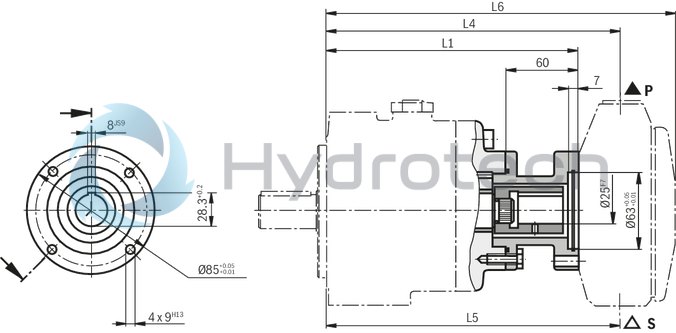
Pump combination P2V7... + GF2 / GP2 / GH2 / GH3 / AZPF / A10VSO
Dimensions in mm
|
PV7 frame size |
L1 |
L2 |
|
mm |
mm |
|
|
10 |
168 |
36 |
|
16 |
192 |
47 |
|
25 |
204 |
47 |
|
40 |
213,6 |
47 |
|
63 |
236,5 |
47 |
|
100 |
268,5 |
47 |
|
PGF2/PGP2 size |
L3 |
L4 |
|
mm |
mm |
|
|
006 |
65 |
116 |
|
008 |
67 |
119,5 |
|
011 |
69,5 |
125 |
|
013 |
72 |
130 |
|
016 |
74,5 |
135 |
|
019 |
77,5 |
141 |
|
022 |
80,5 |
147 |
|
PGF2/PGP2 size |
L3 |
L4 |
|
mm |
mm |
|
|
003 |
51 |
102,5 |
|
005 |
54 |
110 |
|
006 |
55,5 |
112,5 |
|
008 |
57 |
116 |
|
PGH3 size |
L3 |
L4 |
|
mm |
mm |
|
|
011 |
60 |
121,5 |
|
013 |
62,5 |
126,5 |
|
016 |
65 |
131.5 |
|
AZPF size |
L3 |
L4 |
|
mm |
mm |
|
|
004 |
40 |
85 |
|
005 |
41 |
87,5 |
|
008 |
43 |
91,5 |
|
011 |
47 |
96,5 |
|
014 |
47,5 |
101,5 |
|
016 |
47,5 |
105 |
|
019 |
47,5 |
110 |
|
022 |
55 |
115,5 |
|
A10VSO size |
L3 |
L4 |
|
mm |
mm |
|
|
010 |
1481) |
164; 1792) |
|
018 |
145 |
195 |
| 1) | Pipe connections axial |
| 2) | Depending on contoller (see RE 92713) |
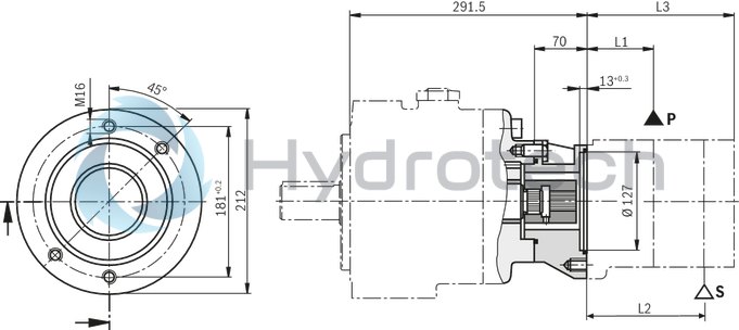
Pump combination P2V7... + GF3 / GP3 / VV1 / VV2 / GH4 / A10VO28
Dimensions in mm
|
PV7 frame size |
L1 |
|
mm |
|
|
16 |
215 |
|
25 |
227 |
|
40 |
237 |
|
63 |
259,5 |
|
100 |
291,5 |
|
PGF3/PGP3 size |
L2 |
L3,L4 |
|
mm |
mm |
|
|
020 |
144,5 |
79,5 |
|
022 |
146,5 |
80,5 |
|
025 |
150,5 |
82,5 |
|
032 |
159,5 |
87 |
|
040 |
169,5 |
92 |
|
050 |
182,5 |
98,5 |
|
PVV.UMB |
L2 |
L3 (P) |
L4 (S) |
|
mm |
mm |
mm |
|
|
PVV1 |
156 |
133 |
63,5 |
|
PVV2 |
163 |
38,1 |
120,6 |
|
PGH4 size |
L2 |
L3,L4 |
|
mm |
mm |
|
|
020 |
147 |
70,5 |
|
025 |
152 |
73 |
|
032 |
159 |
76,5 |
|
040 |
166 |
80 |
|
050 |
176 |
85 |
|
063 |
190 |
92 |
|
080 |
204 |
99 |
|
100 |
224 |
109 |
|
A10VO size |
L2 |
L3 |
L4 |
|
mm |
mm |
mm |
|
|
028 |
194 |
164,5 |
164,5 |
Pump combination P2V7/63... + VV4 / VV5
Dimensions in mm

|
L1 |
L2 |
L3 |
|
|
mm |
mm |
mm |
|
|
PVV4...UMC |
38,1 |
125,5 |
186 |
|
PVV5...UMC |
42,9 |
153,2 |
216 |
Pump combination P2V7/100... + VV4 / VV5
Dimensions in mm
|
L1 |
L2 |
L3 |
|
|
mm |
mm |
mm |
|
|
PVV4...UMC |
38,1 |
125,5 |
186 |
|
PVV5...UMC |
42,9 |
153 |
216 |
Pump combination P2V7... + GF1...
Dimensions in mm
|
PV7 frame size |
L1 |
L2 |
|
mm |
mm |
|
|
10 |
168 |
36 |
|
16 |
192 |
47 |
|
25 |
204 |
47 |
|
GF1 size |
L3 |
L4 |
|
mm |
mm |
|
|
1,7 |
8,6 |
86 |
|
2,2 |
48,6 |
86 |
|
2,8 |
49,7 |
88,6 |
|
3,2 |
50,5 |
89,9 |
|
4,1 |
52,4 |
93,6 |
|
5,0 |
54,2 |
97,3 |
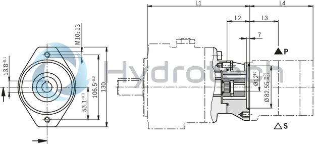
Pump combination P2V7... + PR4-Mini
Dimensions in mm
|
PV7 frame size |
L1 |
L2 |
L4 |
|
mm |
mm |
mm |
|
|
10 |
178 |
46 |
247 |
|
16 |
208 |
63 |
277 |
|
25 |
220 |
63 |
289 |
|
40 |
229,6 |
63 |
298,6 |
|
63 |
252,5 |
63 |
321,5 |
|
100 |
284,5 |
63 |
353,5 |
| Note: The suction port of PR4 should be located above the pressure port! |
Pump combination P2V7... + PR4 standard
Dimensions in mm
|
Piston |
L4 |
L5 |
L6 |
|
mm |
mm |
mm |
|
|
3;5 |
231,5 |
231,5 |
279 |
|
10 |
231,5 |
240,5 |
312,5 |
PV7/16... to PV7/100... + PR4 standard
Dimensions in mm
|
PV7 frame size |
L1 |
L4 |
L5 |
L6 |
|||
|
3/5 Piston |
10 pistons |
3/5 Piston |
10 pistons |
3/5 Piston |
10 pistons |
||
|
mm |
mm |
mm |
mm |
mm |
mm |
mm |
|
|
16 |
205 |
243,5 |
243,5 |
243,5 |
252,5 |
291 |
324,5 |
|
25 |
217 |
255,5 |
255,5 |
255,5 |
264,5 |
303 |
336,5 |
|
40 |
226,6 |
265,1 |
265,1 |
265,1 |
274,1 |
312,6 |
346,1 |
|
63 |
249,5 |
288 |
288 |
288 |
297 |
335,5 |
369 |
|
100 |
281,5 |
320 |
320 |
320 |
329 |
367,5 |
401 |
SAE connection flanges, max. operating pressure 210 bar
Dimensions in mm
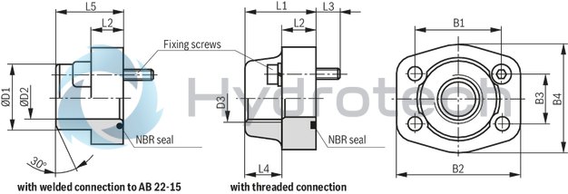
| The material nos. include the flange, the O-ring and the fixing screws. | |
| Pipe thread “G“ to ISO 228/1 |
|
NG |
Seal material |
Part number |
For pump type |
||
|
Welded connection |
Threaded connection |
Suction port |
Pressure port |
||
|
1 1/4 |
NBR |
R900012946 |
R900014153 |
– |
PV7/63-... |
|
1 1/2 |
NBR |
R900013501 |
R900014827 |
PV7/40-... |
PV7/100-... |
|
2“ |
NBR |
R900013502 |
R900014829 |
PV7/63-... |
– |
|
2 1/2“ |
NBR |
R900013503 |
R900024205 |
PV7/100-... |
– |
|
NG |
B1 |
B2 |
B3 |
B4 |
D1 |
D2 |
D3 |
L1 |
L2 |
L3 |
L4 |
L5 |
Mounting screws |
|
mm |
mm |
mm |
mm |
mm |
mm |
mm |
mm |
mm |
mm |
mm |
mm |
||
|
1 1/4 |
58,7 |
79 |
30,2 |
68 |
38 |
30 |
G1 1/4 |
41 |
21 |
18 |
22 |
42 |
M10-8.8 |
|
1 1/2 |
69,9 |
95 |
35,7 |
76 |
42 |
36 |
G1 1/2 |
44 |
25 |
18 |
24 |
57 |
M12-8.8 |
|
2“ |
77,8 |
102 |
42,9 |
90 |
61 |
49 |
G2 |
45 |
25 |
18 |
26 |
46 |
M12-8.8 |
|
2 1/2“ |
88,9 |
114 |
50,8 |
104 |
76 |
62 |
G2 1/2 |
50 |
25 |
18 |
30 |
50 |
M12-8.8 |
Notes on the engineering of multiple pumps
PV7 pumps can be combined as a standard. Each pump is fitted with a splined, second shaft end. When the PV7 is operated as fixed displacement pump, the fixed displacement pump must be used as rear pump. The general technical data are the same as that of the single pump. The pump that is subjected to higher loads (pressure x flow) should be the first pump stage. When several pumps are combined, the torques that occur can reach impermissibly high values. The sum of torques must not exceed the permissible values (see table) Combination parts must be listed as separate items on the order. The combination parts include the required seals and screwsSingle pump
Combination pump
|
PV7 frame size |
Max. perm. input torque Tmax Nm |
Max. perm. output torque Tout max Nm |
|
10 |
90 |
45 |
|
16 |
140 |
70 |
|
25 |
180 |
90 |
|
40 |
280 |
140 |
|
63 |
440 |
220 |
|
100 |
680 |
340 |
Calculation example:
Pump combination: P2V7/25-30... + V7/25-30
Required max. pressure: pn = 160 bar
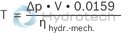
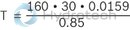
T1,2 = 90 Nm ≤Toff max
T = T1 + T2 = 180 Nm ≤ Tmax
V = Displacement volume in cm3
ηhydr.-mech. = Hydraulic-mechanical efficiency
T = Torque in Nm
Δp = Pressure in bar
The pump combination can be operated on the basis of the calculated data
Engineering notes
Comprehensive notes and suggestions can be found in The Hydraulic Trainer, Volume 3, RE 00281, “Planning and design of hydraulic systems“.
When using vane pumps, we recommend that the following notes are observed in particular:
Technical data
All technical data mentioned depend on manufacturing tolerances and are valid under certain boundary conditions. Please note that small tolerances are therefore possible and that different boundary conditions (e.g. viscosity) can also result in changes in the technical data.
Characteristic curves
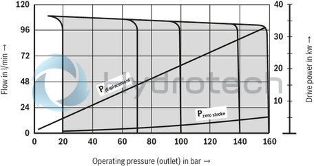
Characteristic curves for flow and absorbed power. Please take the possible maximum operating data into account when dimensioning the drive motor.
Noise/sound pressure level
The sound pressure level values given on Diagrams/characteristic curves were measured in accordance with DIN 45635 part 26.
This means that only the sound emission of the pump is shown. Ambient influences (such as place of installation, piping, etc.) were eliminated. The values are valid for only one pump.
If, for example, two pumps of the same frame size are operated under the same load conditions, the noise level increases according to the following formula
LΣ = 10 lg (100,1•L1 + 100,1•L2)
LΣ = Total noise level
L1 … Li = Sound pressure level of the individual pump
Example: PV7/16 + PV7/16
p = 120 bar
L1 = 56 dB(A)
L2 = 56 dB(A)
LΣ = 10 log (100,1•56 + 100,1•56)
= 59,01 dB(A)
Caution!
The power unit design and influences at the final place of installation of the pump result in the fact that the sound pressure level is usually 5 to 10 dB(A) higher than the value of the pump alone.
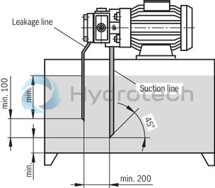
Leakage oil
The external leakage fluid of the pump dissipates a part of the frictional heat. The leakage fluid should be directed with low line resistance directly into the tank. The distance between the leakage line and the suction line must be sufficiently large so that the returning leakage fluid cannot be directly re-aspired. The flow of average, external leakage is shown on Product description. These values must not be used for dimensioning the tanks. The relevant variable for the selection of the tank size is the zero stroke power (see Diagrams/characteristic curves).
Leakage fluid cooler
The values for external leakage fluid given on Technical data are average values that are valid for continuous operation. When the pump goes off stroke, the leakage fluid volume briefly increases due to the pilot fluid of the controller. Reductions in cross-sections, long leakage lines, or also leakage fluid coolers can lead to impermissibly high pressure peaks. Suitable measures, e.g. a check valve in the by-pass must prevent the leakage fluid pressure (pmax = 2 bar) from exceeding the permissible values. Otherwise, the shaft seal ring could be damaged.
Installation notes
Drive
Electric motor + pump carrier + coupling + pump
Caution!
Radial and axial forces acting on the pump drive shaft are not permitted! Motor and pump must be exactly aligned Use a flexible drive couplingInstallation positions
Horizontal position preferredB3
B5
V1
Proposal for piping layout
Dimensions in mm