
BOSCH REXROTH
4WRZE10W6-85-7X/6EG24N9ETK31/A1D3V
R900932993
Proportional Directional Valves
Prop. dir. valves: WRZ* 10.-7x/
BOSCH REXROTH
MATERIAL: R900932993
SUMMARY: Prop. dir. valves: WRZ* 10.-7x/
Quantity in stock: 1
Quantity Details:- Hydrotech Stock: 0 can ship April 22, 2024
- Factory Stock: 1 can ship June 3, 2024
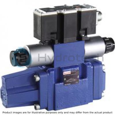
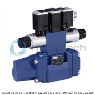
Pilot-operated proportional directional valves type 4WRZ(E)… and 5WRZ(E).52…
Valves of type 4WRZ(E)... are pilot-operated 4-directional valves that are actuated by means of proportional solenoids. Their function is to control the flow direction and size.
Valves of type 5WRZ(E)... are equipped with an additional port "R" (only NG52).
Set-up:
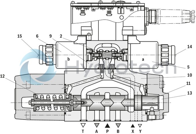
The valve basically consists of:
Pilot control valve (9) with proportional solenoids (5 and 6)
Main valve (10) with main control spool (11) and centering spring (12)
Function:
With de-energized solenoids (5, 6), the main control spool (11) is held in the central position by means of the centering spring (12)
The main control spool (11) is controlled by the pilot control valve (9); the main control spool is proportionally moved, e.g. by actuating solenoid "b" (6)
→ The control spool (2) is moved to the right, pilot oil enters the pressure chamber (13) via the pilot control valve (9) and deflects the main control spool (11) proportionally to the electric input signal
→ Connection from P to A and B to T via orifice-type cross-sections with progressive flow characteristics
Pilot oil supply to the pilot control valve internally via port P or externally via port X
Switching off the solenoid (6)
→ The control spool (2) and main control spool (11) are moved back into the central position
Depending on the spool position, flow occurs from P to A and B to T or P to B and A to T (R)
An optional manual override (14 and 15) can be used to move the control spool (2) without solenoid energization.
Notice:
Accidental activation of the manual override may lead to uncontrolled machine movements!
Notice:
Due to the design principle, internal leakage which may increase over the life cycle is inherent to the valves.
|
01 |
02 |
03 |
04 |
05 |
06 |
07 |
08 |
09 |
10 |
11 |
12 |
13 |
14 |
15 |
16 |
17 |
||
|
4 |
WRZE |
‒ |
7X |
/ |
6E |
G24 |
K31 |
* |
|
01 |
4 main ports |
4 |
|
02 |
Proportional directional valve with electro-hydraulic actuation and integrated electronics |
WRZE |
|
03 |
Size 10 |
10 |
|
Size 16 |
16 |
|
|
Size 25 |
25 |
|
|
Size 32 |
32 |
|
|
Size 52 |
52 |
|
|
04 |
Symbols; for the possible version, see "Symbols/Circuit diagrams" |
E; E1-; E3-; W6-; W8-; W9-; EA; W6A |
|
Rated flow NG10 |
||
|
05 |
25 l/min |
25 |
|
50 l/min |
50 |
|
|
90 l/min |
85 |
|
|
Rated flow NG16 |
||
|
05 |
100 l/min |
100 |
|
125 l/min |
125 |
|
|
150 l/min |
150 |
|
|
180 l/min |
180 |
|
|
Rated flow NG25 |
||
|
05 |
220 l/min |
220 |
|
325 l/min |
325 |
|
|
Rated flow NG32 |
||
|
05 |
360 l/min |
360 |
|
520 l/min |
520 |
|
|
Rated flow NG52 |
||
|
05 |
1000 l/min |
1000 |
|
06 |
Component series 70 ... 79 (70 ... 79: unchanged installation and connection dimensions) |
7X |
|
07 |
For subplate mounting |
no code |
|
For flange connection (only NG 52) |
F |
|
|
08 |
Pilot control valve NG6 |
6E |
|
09
|
Supply voltage 24 V |
G24 |
|
10 |
Without manual override |
no code |
|
With concealed manual override |
N9 1) |
|
|
11 |
Without special type of protection |
no code |
|
Sea water-resistant |
J2) |
|
|
Pilot oil supply and return |
||
|
12 |
External pilot oil supply, external pilot oil return |
no code |
|
Internal pilot oil supply, external pilot oil return |
E |
|
|
Pilot oil supply internal, pilot oil return internal |
ET |
|
|
External pilot oil supply, internal pilot oil return |
T |
|
|
Electrical connection |
||
|
Without mating connector, with connector according to DIN EN 175301-804, separate order |
K31 |
|
|
Electrical interface |
||
|
14 |
Command value ±10 V |
A1 |
|
Command value 4 to 20 mA |
F1 |
|
|
15 |
Without pressure reducing valve |
no code |
|
With pressure reducing valve ZDR 6 DP0-4X/40YM-W80 (fixedly set) |
D3 |
|
|
16 |
NBR seals |
M |
|
FKM seals |
V |
|
|
17 |
Further details in the plain text |
* |
|
1) |
With version “J” → “N” instead of “N9” |
|
|
2) |
For data regarding the seawater-resistant version refer to data sheet 29115-M |
|
For applications outside these parameters, please consult us!
general
|
Type |
4WRZE | ||||||
|
Size |
10 | 16 | 25 | 32 | 52 | ||
|
Installation position |
any, preferably horizontal | ||||||
|
Ambient temperature range |
°C |
-20 … +50 | |||||
|
Storage temperature range |
°C |
-20 … +80 | |||||
|
Weight |
For subplate mounting |
kg |
8 | 12.1 | 18.4 | 42.2 | 79.7 |
|
for flange connection |
kg |
77.7 | |||||
|
with "D3" |
kg |
8.5 | 12.6 | 18.9 | 42.7 | 80.2 | |
|
Sine test according to DIN EN 60068-2-6 |
10 cycles, 10…2000.. 10 Hz with logarithmic frequency changing speed of 1 octave/min, 5 to 57 Hz, amplitude 1.5 mm (p-p), 57 to 2000 Hz, amplitude 10g, 3 axes | ||||||
|
Noise test according to DIN EN 60068-2-64 |
20…2000 Hz, amplitude 0.05g2/Hz (10gRMS) 3 axes, testing time 30 min per axis | ||||||
|
Shock test according to DIN EN 60068-2-27 |
Half-sine 15g / 11 ms, 3 times in positive and 3 times in negative direction per axis, 3 axes | ||||||
|
Damp heat according to DIN EN 60068-2-30 |
Variant 2: +25 °C … +55 °C, 90 % … 97 % relative humidity, 2 cycles á 24 hours | ||||||
hydraulic
|
Size |
10 | 16 | 25 | 32 | 52 | |||
|
Maximum operating pressure |
bar |
315 | 350 | |||||
|
Operating pressure range |
External pilot oil supply |
bar |
30 … 100 | 20 … 100 | ||||
|
Pilot control valve without "D3", internal pilot oil return |
bar |
30 … 100 | ||||||
|
Internal pilot oil supply |
bar |
100 … 315 | 100 … 350 | |||||
|
Maximum return flow pressure |
Port T and R, external pilot oil return |
bar |
315 | 250 | 150 | 250 | ||
|
Port T, internal pilot oil return |
bar |
30 | ||||||
|
Port Y |
bar |
30 | ||||||
|
Maximum flow |
l/min |
170 | 460 | 870 | 1600 | 2800 | ||
|
Nominal flow |
l/min |
25 50 85 |
100 125 150 180 |
220 325 |
360 520 |
1000 | ||
|
Pilot flow |
input signal 0 → 100% |
Port X and Y |
l/min |
3.5 | 5.5 | 7 | 15.9 | 7 |
|
Pilot volume |
switching process 0 → 100% |
cm³ |
1.7 | 4.6 | 10 | 26.5 | 54.3 | |
|
Hydraulic fluid temperature range |
°C |
-20 … +80 | ||||||
|
preferably |
°C |
-40 … +50 | ||||||
|
Viscosity range |
mm²/s |
20 … 380 | ||||||
|
preferably |
mm²/s |
30 … 46 | ||||||
|
Maximum admissible degree of contamination of the hydraulic fluid, cleanliness class according to ISO 4406 (c) 1) |
Pilot control valve |
Class 18/16/13 according to ISO 4406 (c) | ||||||
|
Main valve |
Class 20/18/15 according to ISO 4406 (c) | |||||||
|
Hysteresis |
% |
≤ 6 | ||||||
| 1) | The cleanliness classes specified for the components must be adhered to in hydraulic systems. Effective filtration prevents faults and simultaneously increases the life cycle of the components. For the selection of the filters, see www.boschrexroth.com/filter. |
electrical
|
Size |
10 | 16 | 25 | 32 | 52 | ||
|
Voltage type |
Direct voltage | ||||||
|
Command value overlap |
% |
15 | |||||
|
Maximum solenoid current |
A |
2.5 | |||||
|
Maximum current consumption |
of the amplifier |
A |
1.8 | ||||
|
of the amplifier (impulse current) |
A |
3 | |||||
|
Solenoid coil resistance |
Cold value at 20 °C |
Ω |
2 | ||||
|
Maximum hot value |
Ω |
3 | |||||
|
Actuated time |
% |
100 | |||||
|
Maximum coil temperature 1) |
°C |
+ 150 | |||||
|
Protection class according to DIN EN 60529 |
IP65 (with mating connector mounted and locked) | ||||||
|
Power supply |
V |
24 | |||||
|
Supply voltage range |
V |
19.4 … 35 | |||||
|
Earthing (GND) |
V |
0 | |||||
|
Command value input |
"A1" |
V |
10 | ||||
|
Command value input range |
"F1" |
mA |
4 … 20 | ||||
| 1) | Due to the surface temperatures occurring at the solenoid coils, the European standards ISO 13732-1 and EN 982 need to be adhered to. |
|
Hydraulic fluid |
Classification |
Suitable sealing materials |
Standards |
|
Mineral oils and related hydrocarbons |
HL, HLP |
NBR / FKM |
DIN 51524 |
|
Flame-resistant - containing water |
HFC (Fuchs HYDROTHERM 46M, Petrofer Ultra Safe 620) |
NBR |
ISO 12922 |
|
Important information on hydraulic fluids: For more information and data on the use of other hydraulic fluids please contact us. There may be limitations regarding the technical valve data (temperature, pressure range, life cycle, maintenance intervals, etc.). The flash point of the process and operating medium used must be 40 K over the maximum solenoid surface temperature.
Flame-resistant - containing water: |
|||
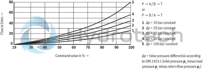
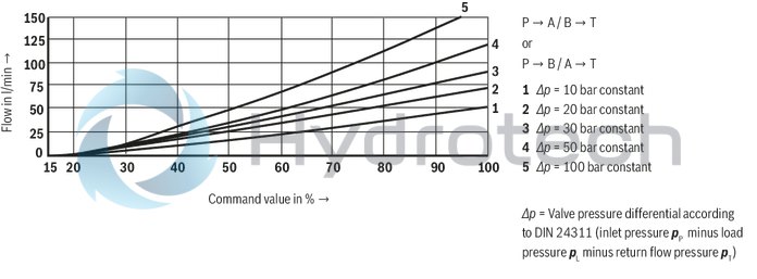
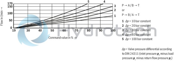
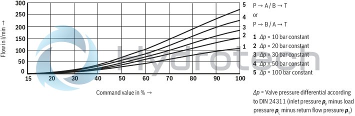
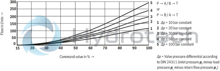
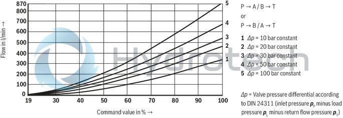
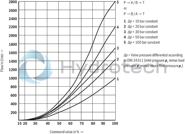
(measured with HLP46, ϑÖl = 40 ±5 °C)
Rated flow 25 l/min at a valve pressure differential of 10 bar
Size 10
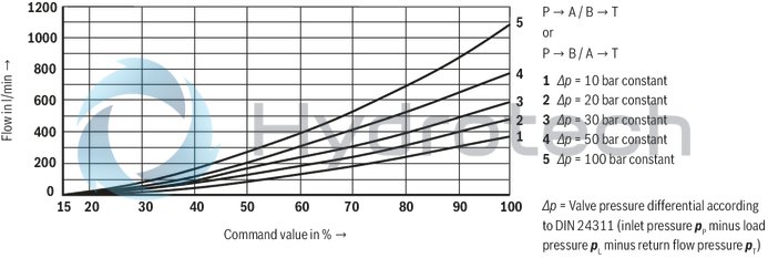
Rated flow 50 l/min at a valve pressure differential of 10 bar
Size 10
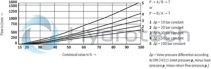
Rated flow 85 l/min at a valve pressure differential of 10 bar
Size 10
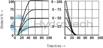
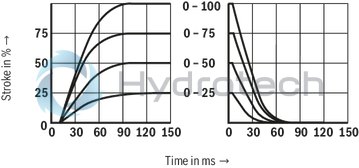
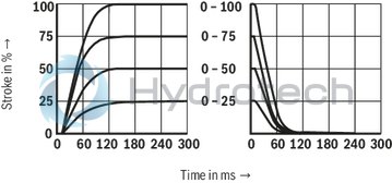
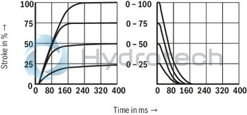
Transition function with stepped electric input signals (ps = 50 bar)
Size 10
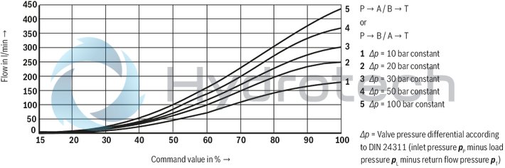
Rated flow 100 l/min at a valve pressure differential of 10 bar
Size 16
Rated flow 125 l/min at a valve pressure differential of 10 bar
Size 16
Rated flow 150 l/min at a valve pressure differential of 10 bar
Size 16

Rated flow 180 l/min at a valve pressure differential of 10 bar
Size 16
Transition function with stepped electric input signals (ps = 50 bar)
Size 16
Rated flow 220 l/min at a valve pressure differential of 10 bar
NG25
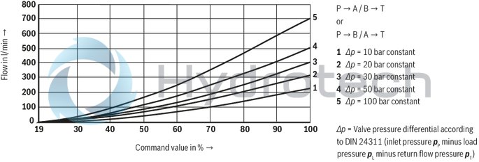
Rated flow 325 l/min at a valve pressure differential of 10 bar
NG25
Transition function with stepped electric input signals (ps = 50 bar)
NG25
Rated flow 360 l/min at a valve pressure differential of 10 bar
Size 32
Rated flow 520 l/min at a valve pressure differential of 10 bar
Size 32
Transition function with stepped electric input signals (ps = 50 bar)
Size 32
Rated flow 1000 l/min at a valve pressure differential of 10 bar
NG52
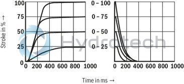
Transition function with stepped electric input signals (ps = 50 bar)
NG52
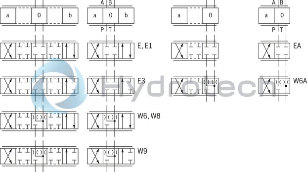
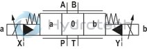
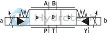
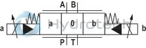
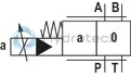
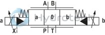
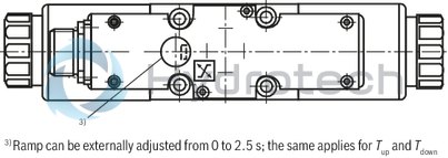
Symbols
|
With symbols E1- and W8-, the following applies: |
|
|
P → A: qvmax |
B → T: qv/2 |
|
P → B: qv/2 |
A → T: qvmax |
|
With symbols E3- and W9-, the following applies: |
|
|
P → A: qvmax |
B → T: blocked |
|
P → B: qv/2 |
A → T: qvmax |
|
(Differential circuit, piston top at port A) |
|
|
Notice: |
|
Pilot oil supply
|
3 Switching positions |
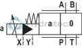
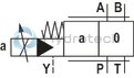
2 Switching positions (Version ".A)" |
|
 |
 |
Type 4WRZ …
External pilot oil supply, external pilot oil return The pilot oil is supplied from a separate control circuit (external). The pilot oil return is not directed into channel T of the main valve, but is separately directed to the tank via port Y (external). |
 |
 |
Type 4WRZ …E…
Internal pilot oil supply, external pilot oil return
The pilot oil supply is implemented from channel P of the main valve (internally). The pilot oil return is not directed into channel T of the main valve, but is separately directed to the tank via port Y (external). In the subplate, port X is to be closed. |
 |
 |
Type 4WRZ …ET…
Internal pilot oil supply; internal pilot oil return
The pilot oil supply is implemented from channel P of the main valve (internally). The pilot oil is directly returned to channel T of the main valve (internally). In the subplate, ports X and Y are to be closed. |
 |
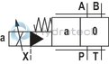 |
Type 4WRZ …T…
External pilot oil supply, internal pilot oil return
The pilot oil is supplied from a separate control circuit (external). The pilot oil is directly returned to channel T of the main valve (internally). In the subplate, port Y is to be closed. |
|
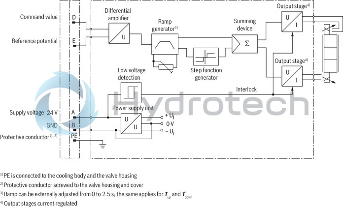
Pin assignment |
Contact |
Assignment interface "A1" |
Assignment interface "F1" |
|
Power supply |
A |
24 VDC (u(t) = 19,4 ... 35 V); Imax = 2 A |
|
|
B |
0 V |
||
|
C |
cannot be used 1) |
||
|
Differential amplifier input (command value) |
D |
±10 V command value; Re > 50 kΩ |
4 ...20 mA command value; Re > 100 Ω |
|
E |
Reference potential command value |
||
|
F |
cannot be used 1) |
||
|
PE |
connected to cooling element and valve housing |
||
|
1) |
Contacts C and F must not be connected! |
||
Command value: Positive command value 0 ... +10 V (or 12 ... 20 mA) at D and reference potential at E cause flow from P → A and B → T.
Negative command value 0 ... –10 V (or 12 ... 4 mA) at D and reference potential at E cause flow from P → B and A → T.
With valves with solenoid on side a (e.g. variant EA and W6A), a positive command value 0 ... +10 V (or 4 ... 20 mA) at D and reference potential at E result in flow from P → B and A → T.
Connection cable: Recommendation: – up to 25 m cable length type LiYCY 7 x 0.75 mm²
– up to 50 m cable length type LiYCY 7 x 1.0 mm²
External diameter 6.5 … 11 mm
Connect shield to PE only on the supply side.
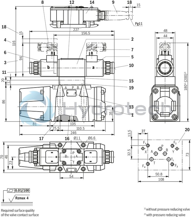
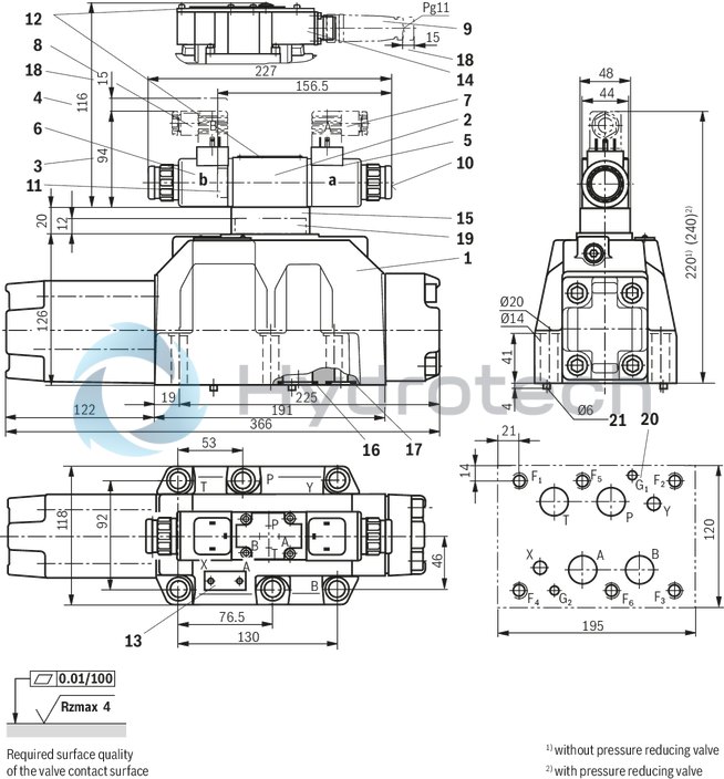
Size 10
Dimensions in mm
|
1 |
Main valve |
|
2 |
Pilot control valve |
|
3 |
Dimension for version 4WRZ (not seawater-resistant) |
|
4 |
Dimension for version 4WRZE |
|
5 |
Proportional solenoid "a" |
|
6 |
Proportional solenoid "b" |
|
7 |
Mating connector "A", color gray, separate order |
|
8 |
Mating connector "B", color black, separate order |
|
9 |
Mating connector according to DIN EN 175201-804, separate order |
|
10 |
Concealed manual override “N9” |
|
11 |
Plug screw for valve with one solenoid |
|
12 |
Name plate pilot control valve |
|
13 |
Name plate main valve |
|
14 |
Integrated electronics (OBE) |
|
15 |
"D3” pressure reducing valve |
|
16 |
Identical seal rings for ports A, B, P and T (T1) |
|
17 |
Identical seal rings for ports X and Y |
|
18 |
Space required to remove the mating connector |
|
19 |
Diversion plate |
|
20 |
Machined valve contact surface; Porting pattern according to ISO 4401-05-05-0-05 |
Recommended valve mounting screws (separate order):
4 hexagon socket head cap screws ISO 4762 - M6 x 45 - 10.9-flZn-240h-LTightening torque MA = 13.5 Nm ± 10 %, material no. R913000258 or
4 hexagon socket head cap screws ISO 4762 - M6 x 45 - 10.9Tightening torque MA = 15.5 Nm ± 10 %
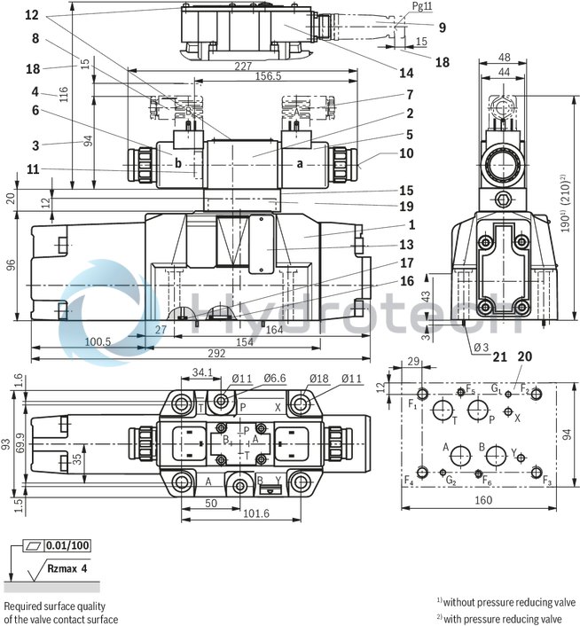
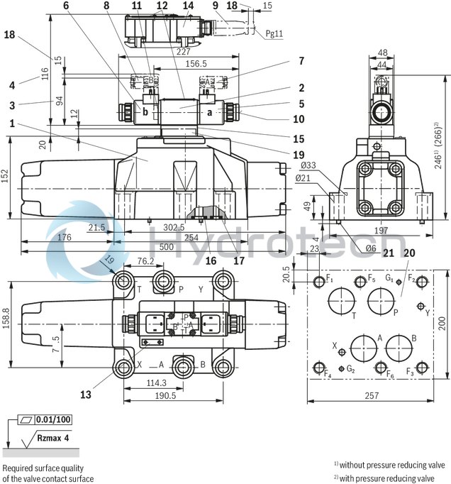
Size 16
Dimensions in mm
|
1 |
Main valve |
|
2 |
Pilot control valve |
|
3 |
Dimension for version 4WRZ (not seawater-resistant) |
|
4 |
Dimension for version 4WRZE |
|
5 |
Proportional solenoid "a" |
|
6 |
Proportional solenoid "b" |
|
7 |
Mating connector "A", color gray, separate order |
|
8 |
Mating connector "B", color black, separate order |
|
9 |
Mating connector according to DIN EN 175201-804, separate order |
|
10 |
Concealed manual override “N9” |
|
11 |
Plug screw for valve with one solenoid |
|
12 |
Name plate pilot control valve |
|
13 |
Name plate main valve |
|
14 |
Integrated electronics (OBE) |
|
15 |
"D3” pressure reducing valve |
|
16 |
Identical seal rings for ports A, B, P, and T |
|
17 |
Identical seal rings for ports X and Y |
|
18 |
Space required to remove the mating connector |
|
19 |
Diversion plate |
|
20 |
Machined valve contact surface; Porting pattern according to ISO 4401-07-07-0-05 |
|
21 |
Locking pin |
Recommended valve mounting screws (separate order):
2 hexagon socket head cap screws ISO 4762 - M6 x 60 - 10.9-flZn-240h-LTightening torque MA = 12.2 Nm ± 10 % , material no. R913000115
4 hexagon socket head cap screws ISO 4762 - M10 x 60 - 10.9-flZn-240h-LTightening torque MA = 58 Nm ± 20 %, material no. R913000116 or
2 hexagon socket head cap screws ISO 4762 - M6 x 60 - 10.9
Tightening torque MA = 15.5 Nm ± 10 %
4 hexagon socket head cap screws ISO 4762 - M10 x 60 - 10.9
Tightening torque MA = 75 Nm ± 20 %
NG25
Dimensions in mm
|
1 |
Main valve |
|
2 |
Pilot control valve |
|
3 |
Dimension for version 4WRZ (not seawater-resistant) |
|
4 |
Dimension for version 4WRZE |
|
5 |
Proportional solenoid "a" |
|
6 |
Proportional solenoid "b" |
|
7 |
Mating connector "A", color gray, separate order |
|
8 |
Mating connector "B", color black, separate order |
|
9 |
Mating connector according to DIN EN 175201-804, separate order |
|
10 |
Concealed manual override “N9” |
|
11 |
Plug screw for valve with one solenoid |
|
12 |
Name plate pilot control valve |
|
13 |
Name plate main valve |
|
14 |
Integrated electronics (OBE) |
|
15 |
"D3” pressure reducing valve |
|
16 |
Identical seal rings for ports A, B, P, and T |
|
17 |
Identical seal rings for ports X and Y |
|
18 |
Space required to remove the mating connector |
|
19 |
Diversion plate |
|
20 |
Machined valve contact surface; Porting pattern according to ISO 4401-08-08-0-05 (ports X and Y as required) |
|
21 |
Locking pin |
Recommended valve mounting screws (separate order):
6 hexagon socket head cap screws ISO 4762 - M12 x 60 - 10.9-flZn-240h-LTightening torque MA = 100 Nm ± 20 %, material no. R913000121 or
6 hexagon socket head cap screws ISO 4762 - M12 x 60 - 10.9Tightening torque MA = 130 Nm ± 20 %
Size 32
Dimensions in mm
|
1 |
Main valve |
|
2 |
Pilot control valve |
|
3 |
Dimension for version 4WRZ (not seawater-resistant) |
|
4 |
Dimension for version 4WRZE |
|
5 |
Proportional solenoid "a" |
|
6 |
Proportional solenoid "b" |
|
7 |
Mating connector "A", color gray, separate order |
|
8 |
Mating connector "B", color black, separate order |
|
9 |
Mating connector according to DIN EN 175201-804, separate order |
|
10 |
Concealed manual override “N9” |
|
11 |
Plug screw for valve with one solenoid |
|
12 |
Name plate pilot control valve |
|
13 |
Name plate main valve |
|
14 |
Integrated electronics (OBE) |
|
15 |
"D3” pressure reducing valve |
|
16 |
Identical seal rings for ports A, B, P, and T |
|
17 |
Identical seal rings for ports X and Y |
|
18 |
Space required to remove the mating connector |
|
19 |
Diversion plate |
|
20 |
Machined valve contact surface; Porting pattern according to ISO 4401-10-09-0-05 (Ports X and Y as required) |
|
21 |
Locking pin |
Recommended valve mounting screws (separate order):
6 hexagon socket head cap screws ISO 4762 - M20 x 80 - 10.9-flZn-240h-LTightening torque MA = 340 Nm ± 20 %, material no. R901035246 or
4 hexagon socket head cap screws ISO 4762 - M20 x 80 - 10.9Tightening torque MA = 430 Nm ± 20 %
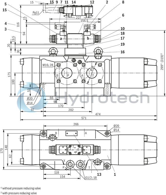
NG52
Dimensions in mm
|
1 |
Main valve |
|
2 |
Pilot control valve |
|
3 |
Dimension for version 4WRZ (not seawater-resistant) |
|
4 |
Dimension for version 4WRZE |
|
5 |
Proportional solenoid "a" |
|
6 |
Proportional solenoid "b" |
|
7 |
Mating connector "A", color gray, separate order |
|
8 |
Mating connector "B", color black, separate order |
|
9 |
Mating connector according to DIN EN 175201-804, separate order |
|
10 |
Concealed manual override “N9” |
|
11 |
Plug screw for valve with one solenoid |
|
12 |
Name plate pilot control valve |
|
13 |
Name plate main valve |
|
14 |
Integrated electronics (OBE) |
|
15 |
Space required to remove the mating connector |
|
16 |
Adapter plate |
|
17 |
"D3” pressure reducing valve |
|
18 |
Diversion plate |
|
19 |
Transport aid |
Recommended valve mounting screws (separate order):
4 hexagon socket head cap screws ISO 4762 - M12 x 70 - 10.9-flZn-240h-LTightening torque MA = 100 Nm ± 20 %, material no. R913000515 or
4 hexagon socket head cap screws ISO 4762 - M12 x 70 - 10.9Tightening torque MA = 130 Nm ± 20 %
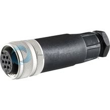
Mating connectors for valves with round connector, 6-pole + PE
7P Z31
Mating connectors for valves with round connector, 6-pole + PE
7P Z31
For valves with round connector according to EN 175201-804, 6-pole + PE as well as 6-pole, compatible with VG 95328Data sheet
Spare parts & repair