
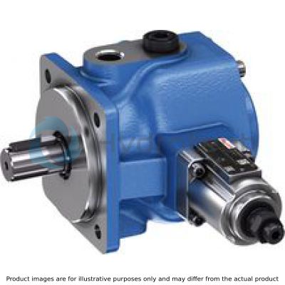
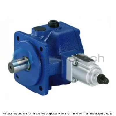
BOSCH REXROTH
PV7-2X/20-25RA01MA0-10
R900950955
Vane Pumps
Variable vane pumps: PV7-2x/20
BOSCH REXROTH
MATERIAL: R900950955
SUMMARY: Variable vane pumps: PV7-2x/20
Quantity in stock: 0
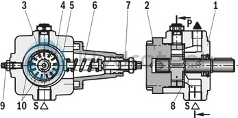
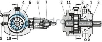
Hydraulic pumps of type PV7...A are direct operated vane pumps with adjustable displacement.
They basically comprise of housing (1), cover (2), rotor (3), vanes (4), stator ring (5), compression spring (6), set screw (7) and control plate (8).
For limitation of the maximum flow, the pump is equipped with a set screw (9).
The driven rotor (3) rotates within the stator ring (5). The centrifugal force presses the vanes (4) guided in the rotor (3) against the internal sliding surfaces of the stator ring (5).
Suction and displacement procedure
The cells (10) necessary to transport the hydraulic fluid are formed by the vanes (4), the rotor (3), the stator (5), the control plate (8) and the cover (2).
The cell volume increases by the rotation of the rotor (3) and via the suction channel (S), the cells (10) are filled with hydraulic fluid. When the largest cell volume is achieved, the cells (10) are separated from the suction side.
If the rotor (3) is rotated further, connection to the pressure side is established, the cells narrow and displace the hydraulic fluid via the pressure channel (P) into the system.
Pressure control
The stator ring (5) is held in the eccentric initial position by the spring (6). The maximum operating pressure required in the system is set at the set screw (7) using the spring (6).
The pressure building up by the load resistance acts at the pressure side on the inner sliding surface of the stator ring (5), against the force of the spring (6).
If the pressure corresponding to the set spring force has been reached, the stator ring (5) is pushed out of its eccentricity in zero position direction. The flow settles at the set value which is just removed. If the peak pressure set at the spring (6) is reached, the pump controls the flow to almost zero. The operating pressure is maintained and only the leakage is replaced. In this way, the power loss and heating of the hydraulic fluid are kept to a minimum.
PV7-1X/06…A…
PV7-2X/20…A…
Thanks to their specific design, PV7-type vane pumps with adjustable displacement boast low flow pulsation and achieve very high repetition accuracies with low pressure peaks during the down control. The noise optimization achieved by adjusting the height adjustment screw provides for a low operating noise. Hydrodynamically lubricated plain bearings ensure a long life cycle.
|
01 |
02 |
03 |
04 |
05 |
06 |
07 |
08 |
09 |
10 |
11 |
|||
|
PV7 |
– |
/ |
R |
A |
01 |
M |
A |
– |
|
Type |
|||
|
01 |
Vane pump, direct operated, maximum operating pressure 100 bar |
PV7 |
|
|
Component series |
|||
|
02 |
Frame size 06, component series 10 to 19, unchanged installation and connection dimensions |
1X |
|
|
Frame size 20, component series 20 to 29, unchanged installation and connection dimensions |
2X |
||
|
Frame sizes BG |
Sizes NG [cm3] |
||
|
03 |
BG 06 |
10 |
06-10 |
|
14 |
06-14 |
||
|
BG 20 |
20 |
20-20 |
|
|
25 |
20-25 |
||
|
Direction of rotation |
|||
|
04 |
When looking at the drive shaft, right |
R |
|
|
Drive shaft |
|||
|
05 |
Parallel keyed shaft |
A |
|
|
Line connections |
|||
|
06 |
Suction and pressure port with pipe thread according to DIN EN ISO 228-1 |
01 |
|
|
Seals |
|||
|
07 |
NBR seals, suitable for mineral oil HL and HLP according to DIN 51524 |
M |
|
|
Control system |
|||
|
08 |
Direct operated |
A |
|
|
Adjustment device |
|||
|
09 |
Set screw (standard) |
0 |
|
|
Controller with lock |
3 |
||
|
Zero stroke pressure range 1) |
|||
|
10 |
V7/06-10 |
25 to 50 bar |
05 |
|
50 to 100 bar |
10 |
||
|
V7/06-14 |
15 to 40 bar |
04 |
|
|
40 to 70 bar |
07 |
||
|
V7/20 |
25 to 50 bar |
05 |
|
|
50 to 100 bar |
10 |
||
|
11 |
Further details in the plain text |
||
| 1) | In the condition as supplied, the zero stroke pressure is set to the smallest value |
Preferred types (available at short notice)
Pump with customer-specific setting:
PV7-1X/06-14RA01MA0-07-P50, pzero stroke = 50 bar PV7-1X/06-14RA01MA0-07-Q20, qV max = 20 l/minThe pump is set to the desired values. The perfect operating noise is set at the desired zero stroke pressure. Without any clear text setting information the flow and the zero stroke pressure will be set to the relevant maximum values.
|
Frame size |
|
06 | 20 | ||||
|
Size |
|
10 | 14 | 20 | 25 | ||
|
Component series |
|
1X | 2X | ||||
|
Mounting type |
|
Flange mounting | |||||
|
Line connections |
|
Pipe thread | |||||
|
Installation position |
|
any, preferably horizontal | |||||
|
Shaft load |
|
Radial and axial forces cannot be transmitted | |||||
|
Direction of rotation |
|
Clockwise rotation (looking at the shaft end) | |||||
|
Drive speed |
n |
rpm |
900 ... 1,800 | ||||
|
Displacement |
Vg |
cm³ |
10 | 14 | 20 | 25 | |
|
Admissible drive torque |
Tmax |
Nm |
50 | 110 | |||
|
Flow, max. 1) |
qV |
l/min |
14.5 | 20 | 29 | 36 | |
|
Leakage flow in the zero stroke 2) |
qVL |
l/min |
1.7 | 2 | 2.4 | ||
|
Operating pressure, absolute |
Inlet |
pmin-max |
bar |
0.8 ... 2.5 | |||
|
Outlet |
pmax |
bar |
100 | 70 | 100 | ||
|
Leakage output |
pmax |
bar |
2 | ||||
|
Mass |
m |
kg |
6.3 | 11.4 | |||
|
Change in flow 3) |
qV |
l/min |
7.5 | 14 | |||
| 1) | at n = 1450 rpm, p = 10 bar, v = 41 mm2/s |
| 2) | With operating pressure output = pzero stroke max |
| 3) | With one rotation of the set screw and n = 1450 rpm |
Hydraulic fluid
|
Permissible hydraulic fluid 1) |
Mineral oil (HLP) to DIN 51524-2 | |
|
Hydraulic fluid temperature range 2) |
°C |
-10 … +70 |
|
Viscosity range 3) |
mm²/s |
10 … 160 |
|
Admissible start viscosity 4) 5) |
mm²/s |
800 200 |
|
Maximum admissible degree of contamination of the hydraulic fluid 6) |
Class 19/16/13 according to ISO 4406 (c) |
| 1) | Other hydraulic fluids on request |
| 2) | Observe the admissible viscosity range! |
| 3) | at operating temperature |
| 4) | in case of start-up in delivery operation |
| 5) | in case of start-up in zero stroke operation |
| 6) | The cleanliness classes specified for the components must be adhered to in hydraulic systems. Effective filtration prevents faults and simultaneously increases the life cycle of the components. For the selection of the filters, see www.boschrexroth.com/filter. |
For applications outside these parameters, please consult us!
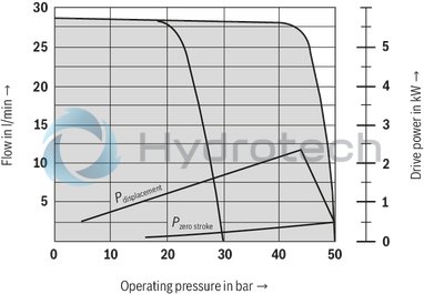
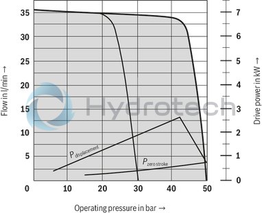
PV7‒../06-10
PV7‒../06-10....A0-05...
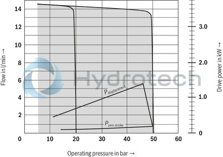
PV7‒../06-10....A0-10...
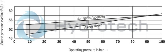
Sound pressure level
Notice
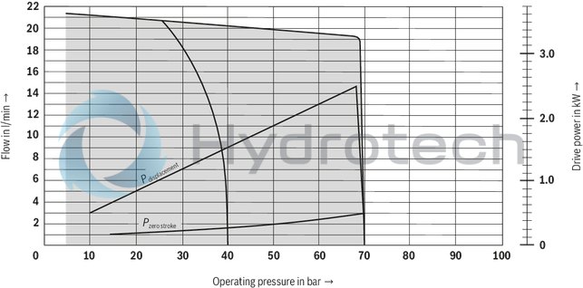
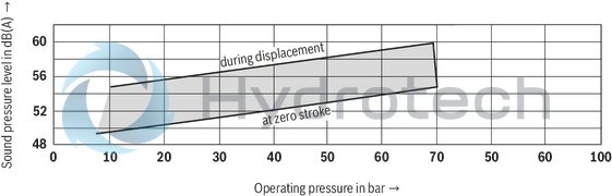
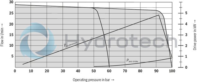
Characteristic curves measured with n = 1450 min-1; ν = 41 mm2/s; θ = 50 °C
Sound pressure level measured in the sound measuring chamber according to DIN 45635, sheet 26; distance: Microphone ‒ Pump = 1 m
PV7‒../06-14
PV7‒../06-14....A0-04...
PV7‒../06-14....A0-07...
Sound pressure level
Notice
Characteristic curves measured with n = 1450 min-1; ν = 41 mm2/s; θ = 50 °C
Sound pressure level measured in the sound measuring chamber according to DIN 45635, sheet 26; distance: Microphone ‒ Pump = 1 m
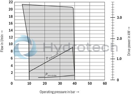
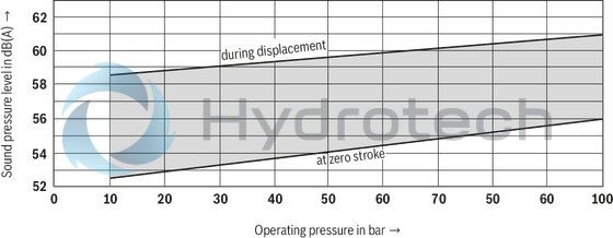
PV7‒../20-20
PV7‒../20-20....A0-05...
PV7‒../20-20....A0-10...
Sound pressure level
Notice
Characteristic curves measured with n = 1450 min-1; ν = 41 mm2/s; θ = 50 °C
Sound pressure level measured in the sound measuring chamber according to DIN 45635, sheet 26; distance: Microphone ‒ Pump = 1 m
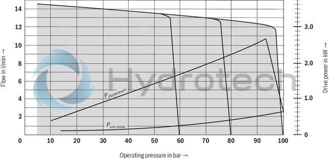
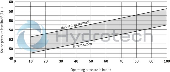
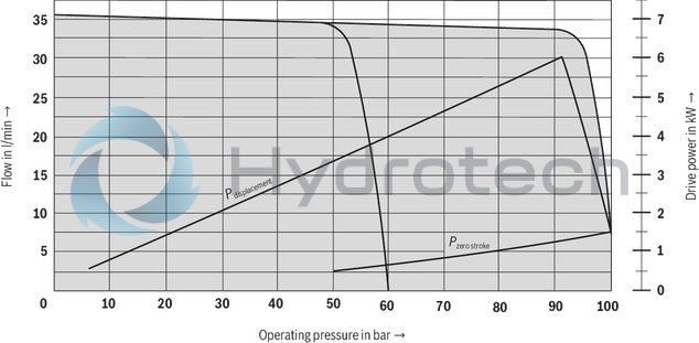
PV7‒../20-25
V7‒../20-25....A0-05...
V7‒../20-25....A0-10...
Sound pressure level
Notice
Characteristic curves measured with n = 1450 min-1; ν = 41 mm2/s; θ = 50 °C
Sound pressure level measured in the sound measuring chamber according to DIN 45635, sheet 26; distance: Microphone ‒ Pump = 1 m

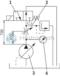
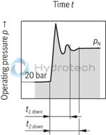
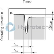
The control times apply to the shown measurement set-up.
With different set-ups and other line lengths, the control times change, as well.
Circuit diagram
|
1 |
Directional valve (switching time duration 30 ms) |
|
2 |
Throttle for setting the pressure during displacement |
|
3 |
Hydraulic pump |
|
4 |
pressure tapping point |
Down control
qv displacement → qv zero stroke
|
Pump type |
Pressure |
Control times (average) |
||
|
pnbar |
pmax 1) |
t1 down |
t2 down |
|
|
06-10...10 |
100 bar |
150 bar |
85 |
90 |
|
06-10...05 |
50 bar |
130 bar |
70 |
110 |
|
06-14...07 |
70 bar |
130 bar |
80 |
100 |
|
06-14...04 |
40 bar |
100 bar |
65 |
90 |
|
20-20...10 |
100 bar |
170 bar |
80 |
125 |
|
20-25...10 |
100 bar |
170 bar |
80 |
125 |
|
20-25...05 |
50 bar |
120 bar |
60 |
85 |
| 1) | Admissible pressure peaks |
Up control
qv zero stroke → qv displacement
|
Pump type |
Pressure |
Control times (average) |
|
|
pnbar |
t1 up |
t2 up |
|
|
06-10...10 |
100 bar |
35 |
60 |
|
06-10...05 |
50 bar |
20 |
30 |
|
06-14...07 |
70 bar |
30 |
50 |
|
06-14...04 |
40 bar |
20 |
35 |
|
20-20...10 |
100 bar |
25 |
45 |
|
20-25...10 |
100 bar |
25 |
45 |
|
20-25...05 |
50 bar |
20 |
40 |
PV7-../06
Dimensions in mm
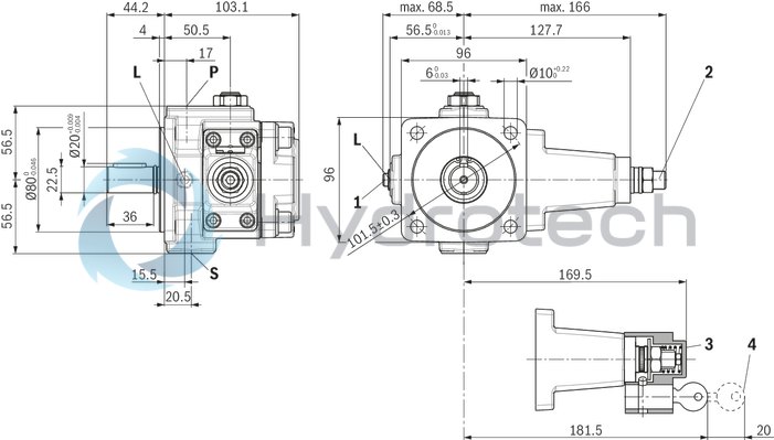
|
1 |
Flow control |
|
2 |
Pressure adjustment by means of set screw (standard), ordering code ...0... |
|
3 |
Lock (optional), ordering code ...3... |
|
4 |
Space required to remove the key |
Ports
|
Denomination |
Size |
|
|
S |
Suction port |
G1/2 |
|
P |
Pressure port |
G3/8 |
|
L |
Leakage connection |
G1/4 |
Adjustment information
Flow control (1)
with clockwise rotation, reduction of the flow with counterclockwise rotation, increase in flowPressure adjustment (2)
with clockwise rotation, increase in the operating pressure with counterclockwise rotation, reduction of the operating pressurePV7-../20
Dimensions in mm
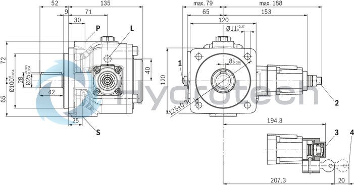
|
1 |
Flow control |
|
2 |
Pressure adjustment by means of set screw (standard), ordering code ...0... |
|
3 |
Lock (optional), ordering code ...3... |
|
4 |
Space required to remove the key |
Ports
|
Denomination |
Size |
|
|
S |
Suction port |
G3/4 |
|
P |
Pressure port |
G1/2 |
|
L |
Leakage connection |
G1/4 |
Adjustment information
Flow control (1)
with clockwise rotation, reduction of the flow with counterclockwise rotation, increase in flowPressure adjustment (2)
with clockwise rotation, increase in the operating pressure with counterclockwise rotation, reduction of the operating pressureWhen using vane pumps, we recommend particularly observing the information specified below.
Project planning, assembly and commissioning of the vane pump require the employment of trained experts.
Technical data
All specified characteristic depend on production tolerances and are valid at certain boundary conditions.
Please note that consequently, certain scatter ranges are possible and that with changed boundary conditions (e.g. viscosity), the characteristics may also change.
Characteristic curves for flow and consumed power
When designing the drive motor, please observe the maximum application parameters possible.
Noise
The values for sound pressure level shown in the section "Diagrams/characteristic curves" have been measured according to DIN 45635 part 26.
That means only the sound emission of the pump is shown. Environmental influences (such as place of installation, piping, etc.) have been eliminated. The values are in each case only valid for one pump.
Notice
Due to the power unit construction and the influence at the final place of installation of the pump, the sound pressure level will usually be 5 to 10 dB(A) higher than the value of the pump itself.
Leakage
In the section "Technical Data", the average external leakage of the pumps is specified. Please note that these values may only be used as project planning aid for designing cooler sizes and line cross-sections. The dimension relevant for the dimensioning of the tanks is the zero stroke performance (see characteristic curves).
Cross-section restrictions, however, also leakage coolers may lead to inadmissibly high pressure peaks in the leakage line.
Pressure limitation
Pressure controllers are no protection against excessive pressure. In the hydraulic system, a separate pressure relief valve is to be provided.
Fluid tank
Adjust useful volume of the tank to the operating conditions. The admissible fluid temperature must not be exceeded; use coolers, if necessary.
Lines and connections
Remove the protective plug at the pump. We recommend using seamless precision steel pipes according to DIN 2391 and releasable pipe connections. Select the inner width of the pipes according to the connections. Pipelines and fittings must be carefully cleaned before assembly.Proposal for piping layout
Minimum dimensions [mm]
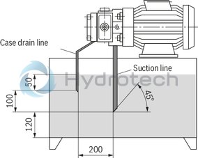 Lay the leakage line so that the pump cannot run empty! Leakage and return fluid must not be directly sucked in again under any circumstances!
Filter
Use a return flow or pressure filter, if possible.
(Suction filters only in connection with underpressure switch / clogging indicator).
Hydraulic fluid
Please observe our provisions according to data sheet 90220. We recommend brand hydraulic fluids Different hydraulic fluid types must not be mixed as this might result in degradation and deterioration of the lubricity. According to the operating conditions, the hydraulic fluid must be renewed at certain time intervals. In this connection, it is also necessary to clean the hydraulic fluid tank from residues.Drive
Electric motor + pump carrier + coupling + pump
 No radial and axial forces on the pump drive shaft admissible! Motor and pump must be exactly aligned! Use a torsionally flexible coupling.
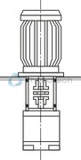
Installation positions
Horizontal position preferred
B3

B5

V1
Bleeding
All vane pump of type PV7...A are self-priming. Before the initial commissioning, the pump must be bled in order to protect it from damage. For the initial commissioning, we recommend filling the housing via the leakage line. Observe the filter rating! This increases the operational safety and prevents wear in case of unfavorable installation conditions. If the pump does not deliver medium without bubbles after approx. 20 sec., the system must be checked once again. After the operating value has been reached, check the pipe connections for leak-tightness. Check the operating temperature.Commissioning
Check whether the system has been assembled carefully and properly. Observe the arrows indicating the direction of rotation of the motor and the pump. Start up the pump without load and allow to pump at zero pressure for some seconds in order to allow for sufficient lubrication. Do not operate the pump without hydraulic fluid under any circumstances!Notice
Assembly, maintenance and repair of the pump may only be carried out by authorized, trained and instructed personnel! Use only original Rexroth spare parts! The pump may only be operated with the admissible data. The pump may only be operated if it is in an unobjectionable condition. At all works at the pump (e.g. installation and removal), the system is to be de-energized and depressurized! Unauthorized modifications or changes which impair the safety and function are not admissible! Apply protective devices (e. g. coupling guard)! Existing protective devices must not be removed! The generally valid safety and accident prevention regulations must imperatively be complied with!