
BOSCH REXROTH
4WREEM10W75-2X/G24K34/B6V
R901008707
Proportional Directional Valves
Prop. dir. valves: WRE,WREE* 10.-2x/
BOSCH REXROTH
MATERIAL: R901008707
SUMMARY: Prop. dir. valves: WRE,WREE* 10.-2x/
Quantity in stock: 0
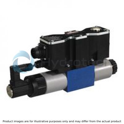
The 4/3 proportional directional valves are designed as direct operated devices in plate design. Operation by means of proportional solenoids with central thread and detachable coil. The solenoids are controlled via integrated electronics.
In version 4WREEM..., the valve is equipped with a symmetric spool overlap and features an operating direction and spool central position monitoring function.
In addition, version 4WREEM...J... has a step function to compensate for this overlap. This means that the spool overlap is passed quickly.
The valve is mainly used in machines with high safety requirements, e. g. in hydraulic press controls.
Set-up:
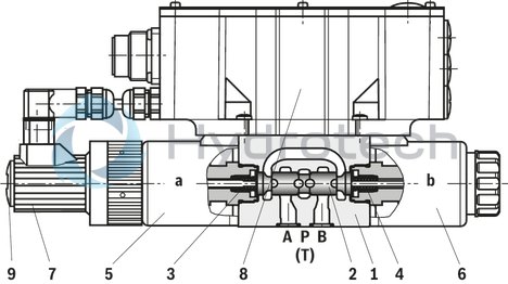
The valve basically consists of:
Housing (1) with connection surface Control spool (2) with compression springs (3 and 4) Solenoids (5 and 6) with central thread Position transducer (7) Integrated electronics (8)Function:
With de-energized solenoids (5 and 6), central position of the control spool (2) due to compression springs (3 and 4) Direct actuation of the control spool (2) by energization of one proportional solenoid, e. g. solenoid "b" (6) Control spool (2) is moved to the left in proportion to the electrical input signal Connection from P to A and B to T via orifice-type cross-sections with progressive flow characteristics Switching off of solenoid “b” (6) Control spool (2) is returned to the central position by the compression spring (3)If no enable signal is available, the output stage is locked and the valve is not functional. The readiness for operation of the output stages can be queried via pin 8. If the supply voltage fails or if no command value is available, the valve control spool is maintained in the central position by centering springs. In this spool position, A, B, P are blocked with spool E and A and B are connected to T with spool W.
Monitoring function:
Monitoring of the control spool position via an inductive position transducer Output signals of the integrated electronics can be evaluated by an external safety control in order to detect any malfunction of the valve The power output stages are blocked by switching off the voltage for enable (pin 3). Notice: Not released for switching off according to EN13849! The output stages are enabled via the enable input (pin 3). The status message is sent via pin 8 The signals to the signal outputs pin 9, pin 10 and pin 11 of the connector are led out. The signals are enabled by the logic switching statuses if the threshold values (+ Xw and – Xw) are exceeded The switching signals are used in a superior control system for monitoring functionsPrecondition for the use as a safety-relevant component in hydraulic circuits:
The entire control must meet the requirements of the standards that are relevant for the application, such as e. g. EN693, EN12622 or EN13849 If safety requires or if the control system detects an error, switching off the supply voltage (pin 1 and pin 2) and enable (pin 3) must cause the valve to be switched off The valve must not be operated vertically with the spool position sensor hanging upside down
Important notice:
The PG fitting (9) must not be opened. Mechanical adjustment of the adjustment nut located below is prohibited and damages the valve!
Notice:
Due to the design principle, internal leakage which may increase over the life cycle is inherent to the valves.
Notice:
The tank line must not be allowed to run empty. With corresponding installation conditions, a preload valve (preload pressure approx. 2 bar) must be installed.
|
01 |
02 |
03 |
04 |
05 |
06 |
07 |
08 |
09 |
10 |
11 |
12 |
13 |
14 |
|||
|
4 |
WRE |
E |
M |
‒ |
2X |
/ |
G24 |
K34 |
/ |
B6 |
V |
* |
|
01 |
4 main ports |
4 |
|
02 |
Proportional directional valve with electrical position feedback |
WRE |
|
03 |
With integrated electronics (OBE) |
E |
|
04 |
Monitoring of control spool position |
M |
|
05 |
Size 6 |
6 |
|
Size 10 |
10 |
|
|
06 |
Symbols; for the possible version, see "Symbols/Circuit diagrams" |
E; E1-; W; W1- |
|
Rated flow NG6 |
||
|
07 |
4 l/min |
4 |
|
8 l/min |
8 |
|
|
16 l/min |
16 |
|
|
32 l/min |
32 |
|
|
Rated flow NG10 |
||
|
07 |
25 l/min |
25 |
|
50 l/min |
50 |
|
|
75 l/min |
75 |
|
|
Option |
||
|
08 |
Without step function |
no code |
|
Electrical compensation of the control spool overlap |
J |
|
|
09 |
Component series 20 ... 29 (20 ... 29: unchanged installation and connection dimensions) |
2X |
|
10 |
Supply voltage 24 V |
G24 |
|
Electrical connection |
||
|
11 |
Connector DIN 43651 |
K34 |
|
Electrical interface |
||
|
12 |
Command value ±10 V |
B6 |
|
Seal material |
||
|
13 |
NBR seals |
V |
|
14 |
Further details in the plain text |
* |
For applications outside these parameters, please consult us!
general
|
Type |
4WREEM | ||
|
Size |
6 | 10 | |
|
Installation position |
horizontal, must not be installed vertically | ||
|
Ambient temperature range |
°C |
-20 … +50 | |
|
Storage temperature range |
°C |
-20 … +80 | |
|
Weight |
kg |
2.4 | 6.5 |
|
MTTFD values according to EN ISO 13849 |
y |
150 | |
hydraulic
|
Size |
6 | 10 | ||
|
Maximum operating pressure |
bar |
315 | ||
|
Maximum operating pressure |
Port P |
bar |
315 | |
|
Port T |
bar |
210 | ||
|
Port A |
bar |
315 | ||
|
Port B |
bar |
315 | ||
|
Maximum flow |
l/min |
90 | 180 | |
|
Nominal flow |
l/min |
4 8 16 32 |
25 50 75 |
|
|
Maximum admissible zero flow |
l/min |
≤ 0.3 | ≤ 0.6 | |
|
Hydraulic fluid |
see table below | |||
|
Hydraulic fluid temperature range |
°C |
-20 … +80 | ||
|
preferably |
°C |
+40 … +50 | ||
|
Viscosity range |
mm²/s |
20 … 380 | ||
|
preferably |
mm²/s |
30 … 46 | ||
|
Maximum admissible degree of contamination of the hydraulic fluid, cleanliness class according to ISO 4406 (c) 1) |
Class 20/18/15 according to ISO 4406 (c) | |||
|
Hysteresis |
% |
≤ 0.1 | ||
|
Range of inversion |
% |
≤ 0.05 | ||
|
Response sensitivity |
% |
≤ 0.05 | ||
|
Zero shift upon change of |
Hydraulic fluid temperature |
%/10 K |
< 0.15 | |
|
Operating pressure |
%/100 bar |
< 0.1 | ||
| 1) | The cleanliness classes specified for the components must be adhered to in hydraulic systems. Effective filtration prevents faults and simultaneously increases the life cycle of the components. For the selection of the filters, see www.boschrexroth.com/filter. |
|
Hydraulic fluid |
Classification |
Suitable sealing materials |
Standards |
|
Mineral oils and related hydrocarbons |
HL, HLP |
NBR / FKM |
DIN 51524 |
|
Flame-resistant - containing water |
HFC (Fuchs HYDROTHERM 46M, Petrofer Ultra Safe 620) |
NBR |
ISO 12922 |
|
Important information on hydraulic fluids: For more information and data on the use of other hydraulic fluids please contact us. There may be limitations regarding the technical valve data (temperature, pressure range, life cycle, maintenance intervals, etc.). The flash point of the process and operating medium used must be 40 K over the maximum solenoid surface temperature.
Flame-resistant - containing water: |
|||
electrical
|
Size |
6 | 10 | ||
|
Voltage type |
Direct voltage | |||
|
Maximum current consumption |
of the amplifier 1) |
A |
2 | |
|
of the amplifier (impulse current) |
A |
3 | ||
|
Actuated time |
% |
100 | ||
|
Maximum coil temperature 2) |
°C |
150 | ||
|
Protection class according to DIN EN 60529 |
IP65 (with mating connector mounted and locked) | |||
|
Command value output |
V |
± 10 | ||
|
Power supply |
V |
24 | ||
|
Supply voltage range |
V |
19 … 35 | ||
|
Earthing (GND) |
V |
0 | ||
|
Enable input range |
"B6" |
V |
8.5 … 35 | |
|
Command value input |
"B6" |
mA |
± 10 | |
|
Actual value output |
"B6" |
V |
± 10 | |
|
Power output stages of signal output |
0 V or UB | |||
|
Control spool position P → A |
V |
24 | ||
|
Control spool position P → B |
V |
24 | ||
|
Control spool position zero position |
V |
24 | ||
| 1) | plus load of switching outputs |
| 2) | Due to the surface temperatures occurring at solenoid coils, the European standards ISO 13732-1 and ISO 4413 need to be adhered to. |
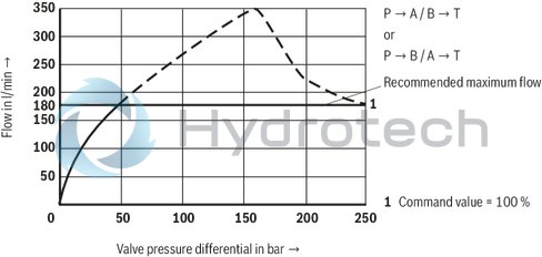
(measured with HLP46, ϑÖl = 40 ±5 °C)
Rated flow 4 l/min at a valve pressure differential of 10 bar
NG6
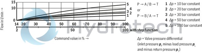
Rated flow 8 l/min at a valve pressure differential of 10 bar
NG6
Rated flow 16 l/min at a valve pressure differential of 10 bar
NG6
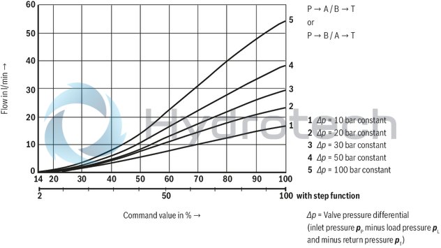
Rated flow 32 l/min at a valve pressure differential of 10 bar
NG6
Performance limit rated flow 4 l/min
NG6
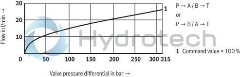
Performance limit rated flow 8 l/min
NG6
Performance limit rated flow 16 l/min
NG6
Performance limit rated flow 32 l/min
NG6
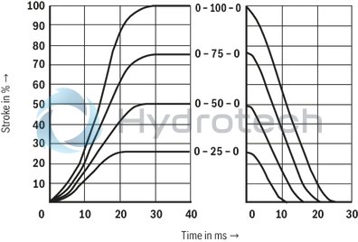
Transition function with stepped electric input signals
NG6
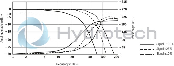
Frequency response
NG6
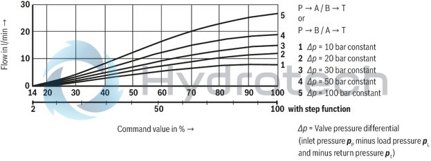
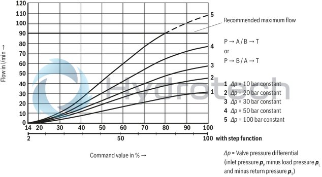
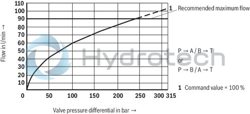
Rated flow 25 l/min at a valve pressure differential of 10 bar
NG10
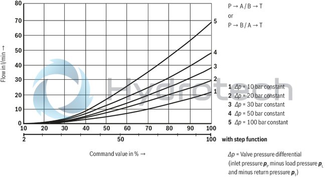
Rated flow 50 l/min at a valve pressure differential of 10 bar
NG10
Rated flow 75 l/min at a valve pressure differential of 10 bar
NG10
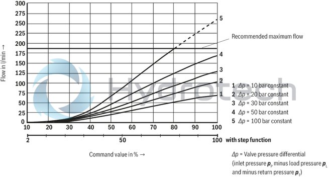
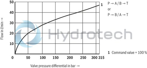
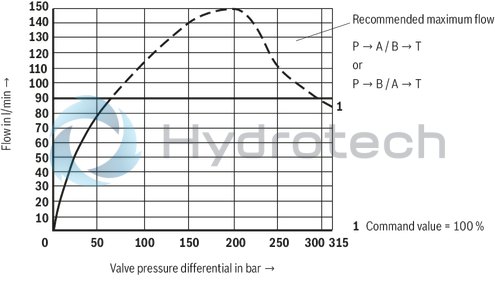
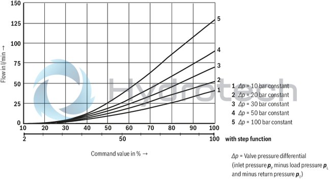
Performance limit rated flow 25 l/min
NG10
Performance limit rated flow 50 l/min
NG10
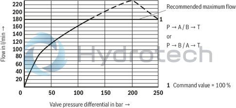
Performance limit rated flow 75 l/min
NG10
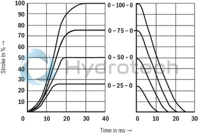
Transition function with stepped electric input signals
NG10
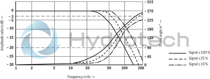
Frequency response
NG10
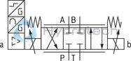
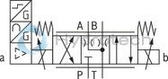
Symbols
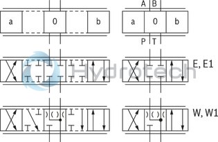
|
With control spool symbol E1- and W1-, the following applies: |
|
|
P → A: qvmax |
B → T: qv/2 |
|
P → B: qv/2 |
A → T: qvmax |
|
Notice: |
|
Type 4WREEM...E...
Type 4WREEM...W...
|
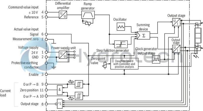
Pin assignment |
Contact |
Signal with interface B6 |
|
Power supply |
1 |
24 VDC (u(t) = 19,0 ... 35 V); Imax = 2 A |
|
2 |
0 V
|
|
|
Enable input |
3 |
8,5 VDC ... 35 VDC |
|
Differential amplifier input (command value) |
4, 5
|
± 10 V command value |
|
6, 7
|
± 10 V actual value |
|
|
Power output stages of signal output |
8 |
0 V or UB |
|
Control spool position P → B |
9 |
24 VDC |
|
Control spool position P → A |
10 |
24 VDC |
|
Control spool position zero position |
11 |
24 VDC |
|
PE |
connected to cooling element and valve housing |
Command value:
Positive command value 0 ... +10 V at pin 4 and reference potential at pin 5 result in flow from P → A and B → T
Negative command value 0 ... –10 V at pin 4 and reference potential at pin 5 result in flow from P → B and A → T
Actual value:
Positive actual value 0 ... +10 V at pin 6 and reference potential at pin 7 result in flow from P → A and B
T
Negative actual value 0 ... -10 V at pin 6 and reference potential at pin 7 result in a flow from P → B and A
T
Connection cable:
Recommendation:
up to 25 m cable length type LiYCY 7 x 0.75 mm²
up to 50 m cable length type LiYCY 7 x 1.0 mm²
Block diagram / pin assignment
Logic switching statuses for control spool position monitoring
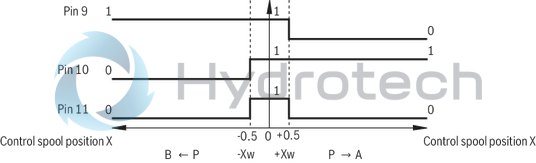
|
Control spool position |
Direction of flow |
logic switching statuses |
||
|
Pin 9 |
Pin 10 |
Pin 11 |
||
|
X < - Xw |
B ← P |
1 |
0 |
0 |
|
- Xw ≤ X ≤ Xw |
- |
1 |
1 |
1 |
|
X > Xw |
P → A |
0 |
1 |
0 |
Marking and adjustment elements
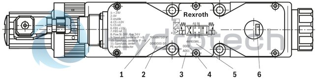
|
1 |
Material number |
|
2 |
Production order number |
|
3 |
Date of production |
|
4 |
Serial number |
|
5 |
Type designation |
|
6 |
Setting the ramp time |
4WREEM 6
Dimensions in mm
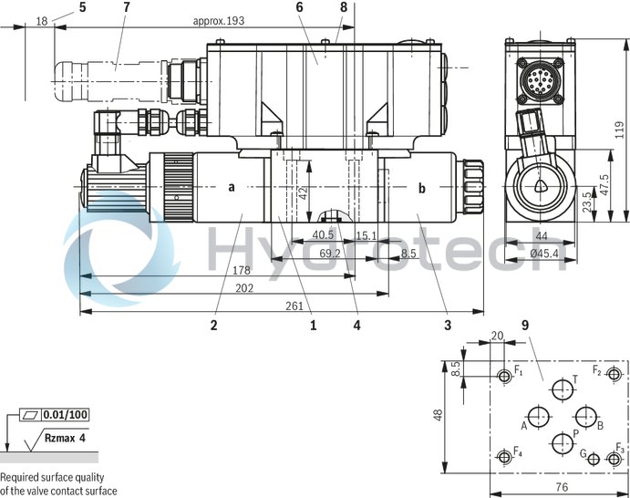
|
1 |
Valve housing |
|
2 |
Proportional solenoid "a" with inductive position transducer |
|
3 |
Proportional solenoid "b" |
|
4 |
R-ring 9.81 x 1.5 x 1.78 (ports P, A, B, T) |
|
5 |
Space required to remove the mating connector |
|
6 |
Integrated electronics (OBE) |
|
7 |
Mating connector according to DIN EN 175201-804, separate order |
|
8 |
Name plate |
|
9 |
Machined valve contact surface; Porting pattern according to ISO 4401-03-02-0-05 (with locating hole) |
Recommended valve mounting screws (separate order):
4 hexagon socket head cap screws ISO 4762 - M5 x 50 - 10.9
tightening torque MA = 8.9 Nm ± 10 %
4WREEM 10
Dimensions in mm
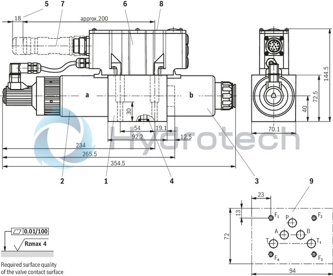
|
1 |
Valve housing |
|
2 |
Proportional solenoid "a" with inductive position transducer |
|
3 |
Proportional solenoid "b" |
|
4 |
R-ring 13.0 x 1.6 x 2.0 (ports P, A, B, T, T1) |
|
5 |
Space required to remove the mating connector |
|
6 |
Integrated electronics (OBE) |
|
7 |
Mating connector according to DIN EN 175201-804, separate order |
|
8 |
Name plate |
|
9 |
Machined valve contact surface; Porting pattern according to ISO 4401-05-04-0-05 |
Recommended valve mounting screws (separate order):
4 hexagon socket head cap screws ISO 4762 - M6 x 40 - 10.9
tightening torque MA = 15.5 Nm ± 10%
Notice:
The dimensions are nominal dimensions which are subject to tolerances.
Mating connectors for valves with round connector, 11-pole + PE
12P N11
Mating connectors for valves with round connector, 11-pole + PE
12P N11
For valves with round connector according to EN 175201-804, 11-pole + PEData sheet
Spare parts & repair