BOSCH REXROTH
M-3SEW6C3X/420MW110RN9XEZ2/V
R901067845
Directional Seat/Poppet Valves
Direct. poppet valves: M-*SEW 6.-3x/
BOSCH REXROTH
MATERIAL: R901067845
SUMMARY: Direct. poppet valves: M-*SEW 6.-3x/
Quantity in stock: 0
2/2 and 3/2 directional seat valve
General
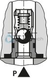
Directional valves of the type SEW are direct operated directional seat valves with solenoid actuation. It controls the start, stop and direction of flow.
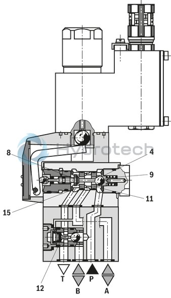
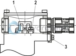
The directional valves basically comprise a housing (1), the solenoid (2), the hardened valve system (3) and the control spool (8).
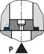
Basic principle
In the initial position, the control spool (8) is pressed onto the seat by the spring (9) and in spool position by the solenoid (2). The force of the solenoid (2) acts via the angled lever (6) and the ball (7) on the control spool (8)
that is sealed on two sides. The chamber between the two sealing elements is connected to port P. Thus, the valve system (3) is pressure-compensated in relation to the actuating forces (solenoid or return spring).
Notices:
The 3/2 directional seat valves have a "negative spool overlap". Therefore, port T must always be connected. That means that during the switching process – from the starting of the opening of one valve seat to the closing of the other valve seat – ports P–A–T are connected with each other. This process takes, however, place within such a short time that it is irrelevant in nearly all applications. The manual override (10) allows for the switching of the valve without solenoid energization. Make sure that the specified maximum flow is not exceeded. A throttle insert must be used for flow limitation, if necessary (see table "Throttle insert, check valve insert").|
The seat arrangement offers the following options: |
||
|
2/2 directional seat valve |
3/2 directional seat valve |
|
|
Symbol |
P 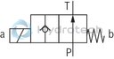
|
U 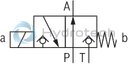
|
|
Initial position |
P and T connected |
P and A connected, T blocked |
|
Spool position |
P blocked |
P blocked, A and T connected |
|
Symbol |
N 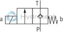
|
C 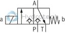
|
|
Initial position |
P blocked |
P blocked, A and T connected |
|
Spool position |
P and T connected |
P and A connected, T blocked |
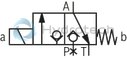
Type M-2SEW 6 N...XE...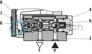
|
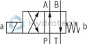
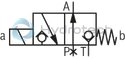
Type M-3SEW 6 U...N9XE...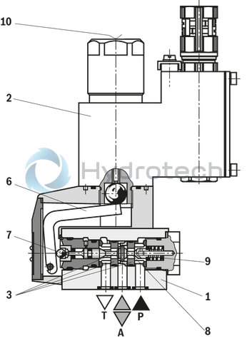
|
Type M-3SEW 6 U...N9XE...
4/2 directional seat valve
With a sandwich plate, the Plus-1 plate, under the 3/2 directional seat valve, the function of a 4/2 directional seat valve is achieved.
Function of the Plus-1 plate:
Initial position:The main valve is not operated. The spring (9) holds the ball (4) on the seat (11). Port P is blocked and A is connected to T. Apart from that, one control line is connected from A to the large area of the control spool (12), which is thus unloaded to the tank. The pressure applied via P now pushes the ball (13) onto the seat (14). Now, P is connected to B, and A to T. Transition position:Upon actuation of the main valve, the control spool (8) is shifted against the spring (9) and pressed onto the seat (15). During this, port T is blocked, while P, A, and B are briefly connected to each other. Switching position:P is connected to A. As the pump pressure acts via A on the large area of the control spool (12), the ball (13) is pressed onto the seat (16). Thus, B is connected to T, and P to A. The ball (13) in the Plus-1 plate has a "positive spool overlap".Notice:
If the annulus area of differential cylinders is not connected to port A, a pressure peak is created in port B during the switching process. This pressure peak may exceed the maximum admissible operating pressure over the permissible limit.
|
The use of the Plus-1 plate and the seat arrangement offer the following options: |
||
|
Symbol |
D |
Y |
|
|
|
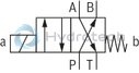
Type M-4SEW 6 Y...N9XE...
Schematic illustration: Initial position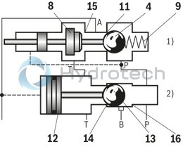
|
Type M-4SEW 6 Y...N9XE...
|
| 1) | 3/2 directional seat valve |
| 2) | Plus-1 plate |
Throttle insert, check valve insert
|
Throttle insert |
Check valve insert |
|
The use of a throttle insert is required if, due to the operating conditions given, flows may arise during the switching processes which exceed the performance limit of the valve. Examples: Accumulator operation, use as pilot control valve with internal pilot fluid tapping.3/2 directional seat valve The throttle insert is inserted into port P of the seat valve. 4/2 directional seat valve The throttle insert is inserted into port P of the Plus-1 plate.
|
The check valve insert allows a free flow from P to A and closes A to P. 3/2 directional seat valve The check valve insert is inserted into port P of the seat valve. 4/2 directional seat valve The check valve insert is inserted into port P of the Plus-1 plate.
|
|
|
|
01 |
02 |
03 |
04 |
05 |
06 |
07 |
08 |
09 |
10 |
11 |
12 |
13 |
14 |
|||
|
M |
– |
SEW |
6 |
3X |
/ |
420 |
M |
XE |
Z2 |
/ |
|
01 |
Mineral oil |
M |
|||
|
02 |
2 main ports |
2 |
|||
|
3 main ports |
3 |
||||
|
4 main ports |
4 |
||||
|
03 |
Seat valve |
SEW |
|||
|
04 |
Size 6 |
6 |
|||
|
Symbols |
|||||
|
05 |
Main ports |
2 |
3 |
4 |
|
|
|
✔ |
– |
– |
P |
|
|
|
✔ |
– |
– |
N |
|
|
|
– |
✔ |
– |
U |
|
|
|
– |
✔ |
– |
C |
|
|
|
– |
– |
✔ |
D |
|
|
|
– |
– |
✔ |
Y |
|
|
06 |
Component series 30 ... 39 (30 ... 39: unchanged installation and connection dimensions) |
3X |
|||
|
07 |
Operating pressure 420 bar |
420 |
|||
|
08 |
Solenoid (air-gap) |
M |
|||
|
09 |
Direct voltage 24 V |
G24 |
|||
|
Alternating voltage 230 V, 50/60 Hz |
W230 R |
||||
|
For further ordering codes for other voltages and frequencies, see chapter "Technical data" |
|||||
|
10 |
With concealed manual override |
N9 |
|||
|
Without manual override |
no code |
||||
|
Explosion protection |
|||||
|
11 |
"Increased safety", for details see chapter "Technical data" - Table "Information on the explosion protection" |
XE |
|||
|
Electrical connection |
|||||
|
12 |
Solenoid with terminal box and cable gland, for details see chapter "Electrical connection" |
Z2 |
|||
|
13 |
Without check valve insert, without throttle insert |
no code |
|||
|
With check valve insert |
P |
||||
|
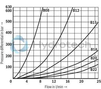
Throttle Ø 0.8 mm |
B08 |
||||
|
Throttle Ø 1.2 mm |
B12 |
||||
|
Throttle Ø 1.5 mm |
B15 |
||||
|
Throttle Ø 1.8 mm |
B18 |
||||
|
Throttle Ø 2.0 mm |
B20 |
||||
|
Throttle Ø 2.2 mm |
B22 |
||||
|
Seal material |
|||||
|
14 |
NBR seals |
no code |
|||
|
FKM seals |
V |
||||
|
Observe compatibility of seals with hydraulic fluid used. (Other seals upon request) |
|||||
|
Notice: |
|||||
For applications outside these parameters, please consult us!
|
Hydraulic fluid |
Classification |
Suitable sealing materials |
Standards |
Data sheet |
|
|
Mineral oils |
HL, HLP, HLPD |
NBR, FKM |
DIN 51524 |
90220 |
|
|
Bio-degradable |
Insoluble in water |
HETG |
FKM |
ISO 15380 |
90221 |
|
HEES |
FKM |
||||
|
Soluble in water |
HEPG |
FKM |
ISO 15380 |
||
|
Flame-resistant |
Containing water |
HFC (Fuchs Hydrotherm 46M, Petrofer Ultra Safe 620 ) |
NBR |
ISO 12922 |
90223 |
|
Important information on hydraulic fluids: For further information and data on the use of other hydraulic fluids, please refer to the data sheets above or contact us. There may be limitations regarding the technical valve data (temperature, pressure range, life cycle, maintenance intervals, etc.). Ignition temperature >180 °C. Flame-resistant – containing water: Maximum operating pressure 210 bar Pressure differential <15 bar Pressure pre-loading at the tank port >20% of the pressure differential, otherwise increased cavitation erosion Life cycle as compared to operation with mineral oil HL, HLP 50 … 100% Maximum hydraulic fluid temperature 60 °C |
|||||
electrical
|
Voltage type |
Direct voltage | AC voltage | |
|
Available voltages |
V |
24 / 48 / 96 / 110 | 110 / 230 |
|
Voltage tolerance (nominal voltage) |
% |
- 5 + 10 |
|
|
Admissible residual ripple |
% |
< 5 | - |
|
Duty cycle/operating mode according to VDE 0580 |
S1 (continuous operation) | ||
|
Switching time according to ISO 6403 |
see table | ||
|
Maximum switching frequency |
1/h |
15000 | 7200 |
|
Nominal power with ambient temperature 20 °C |
W |
17 | |
|
Maximum power with 1.1 x nominal voltage and an ambient temperature of 20 °C |
W |
20.6 | |
|
Protection class according to DIN EN 60529 1) |
IP66 | ||
| 1) | With correctly installed electrical connection |
Special application conditions for a safe application
Maximum ambient temperature:In case of bank assembly, as long as only one solenoid is energized at a time, and in case of individual assembly: +70 °C
In case of bank assembly when more than one solenoid is energized at a time: +60 °C The maximum temperature of the surface of the valve jacket is 120 °C. This has to be considered when selecting the connection cable and/or contact of the connection cable with the surface of the jacket is to be prevented.
Switching times t in ms (installation position: solenoid horizontal)
|
Pressure p |
Flow qV |
DC solenoid |
AC solenoid |
||||||||||||
|
tON without tank pressure |
tOFF |
tON without tank pressure |
tOFF |
||||||||||||
|
U |
C |
D |
Y |
C, U |
D, Y |
U |
C |
D |
Y |
U |
C |
D |
Y |
||
|
70 bar |
25 l/min |
30 |
40 |
30 |
40 |
15 |
15 |
25 |
40 |
25 |
40 |
45 |
65 |
45 |
65 |
|
140 bar |
25 l/min |
30 |
50 |
30 |
50 |
15 |
15 |
25 |
40 |
25 |
40 |
65 |
65 |
65 |
65 |
|
280 bar |
25 l/min |
35 |
60 |
35 |
60 |
15 |
15 |
25 |
45 |
25 |
45 |
75 |
65 |
75 |
65 |
|
320 bar |
25 l/min |
40 |
70 |
40 |
70 |
15 |
15 |
25 |
45 |
25 |
45 |
80 |
65 |
80 |
65 |
|
420 bar |
25 l/min |
45 |
70 |
45 |
70 |
15 |
15 |
30 |
45 |
30 |
45 |
100 |
65 |
100 |
65 |
|
Notice: The switching times were determined at a hydraulic fluid temperature of 40 °C and 46 mm2/s. Deviating hydraulic fluid temperatures can result in different switching times. Switching times change dependent on operating time and application conditions. |
|||||||||||||||
Performance limit: (measured with HLP46, ϑoil = 40 ±5 °C)
|
Symbol |
Comment |
Operating pressure in bar |
Flow in l/min |
|||||
|
P |
A |
B |
T |
|||||
|
2-way circuit |
P |
|
Pressure at P ≥ T |
420 |
‒ |
‒ |
100 |
25 |
|
N |
|
420 |
‒ |
‒ |
100 |
25 |
||
|
3-way circuit |
U |
|
Pressure at P ≥ A ≥ T |
420 |
420 |
‒ |
100 |
25 |
|
C |
|
420 |
420 |
‒ |
100 |
25 |
||
|
2-way circuit (as unloading function only) |
U |
|
Before switching from the initial position to the spool position, pressure must be applied to port A. Pressure at A ≥ T |
‒ |
420 |
‒ |
100 |
25 |
|
C |
|
Pressure at A ≥ T |
‒ |
420 |
‒ |
100 |
25 |
|
|
4-way circuit (flow only possible in the direction of arrow!) |
D |
|
Valve (symbol U) in connection with Plus-1 plate P > A ≥ B > T |
420 |
420 |
420 |
100 |
25 |
|
Y |
|
Valve (symbol C) in connection with Plus-1 plate P > A ≥ B > T |
420 |
420 |
420 |
100 |
25 |
|
|
Notice: Please observe the general notes (see chapter "Information"). The performance limits were determined when the solenoids were at operating temperature, at 10 % undervoltage and without tank preloading. |
||||||||
(measured with HLP46, ϑOil = 40 ±5 °C)
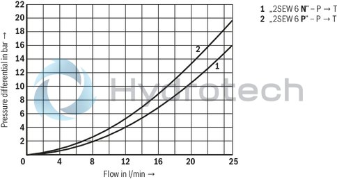
Δp-qV characteristic curves ‒ 2/2 directional seat valve
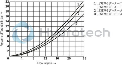
Δp-qV characteristic curves ‒ 3/2 directional seat valve
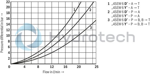
Δp-qV characteristic curves ‒ 4/2 directional seat valve
Δp-qV characteristic curves ‒ Check valve insert
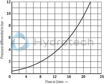
Δp-qV characteristic curves ‒ throttle insert
The type-examination tested valve solenoid of the valve is equipped with a terminal box and a type-tested cable gland.
The connection is polarity-independent.
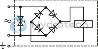
Solenoids to be connected to AC voltage are equipped with an integrated rectifier.
Notice
When establishing the electrical connection, the protective grounding conductor (PE) has to be connected properly.
Properties of the connection terminals and mounting elements
|
Position |
Function |
Connectable line cross-section |
|
1 |
Operating voltage connection |
Single-wire 0.75 … 2.5 mm2 |
|
Finely stranded,0.75 … 1.5 mm2 |
||
|
2 |
Connection for protective earthing conductor |
Single-wire 2.5 mm2 max. |
|
Finely stranded, 1.5 mm2 max. |
||
|
3 |
Connection for potential equalization conductor |
Single-wired, 4 … 6 mm2 |
|
Finely stranded, 4 mm2 |
|
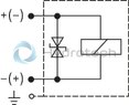
Direct voltage, polarity-independent |
AC voltage |
|
|
Over-current fuse and switch-off voltage peak
|
Voltage data in the valve type code |
Nominal voltage valve solenoid |
Rated current valve solenoid |
Rated current for external miniature fuse: Medium time-lag (M) according to DIN 41571 and EN/IEC 60127 |
Rated voltage of external miniature fuse: Medium time-lag (M) according to DIN 41571 and EN/IEC 60127 |
Maximum voltage value when switching off |
Interference protection circuit |
|
G24 |
24 V DC |
0.708 A DC |
800 mA |
250 V |
–90 V |
Suppressor diode bi-directional |
|
G48 |
48 V DC |
0.354 A DC |
400 mA |
250 V |
–200 V |
|
|
G96 |
96 V DC |
0.177 A DC |
200 mA |
250 V |
–370 V |
|
|
G110 |
110 V DC |
0.155 A DC |
200 mA |
250 V |
–390 V |
|
|
W110R |
110 V AC |
0.163 A AC |
200 mA |
250 V |
–3 V |
Bridge rectifier and suppressor diode |
|
W230R |
230 V AC |
0.078 A AC |
80 mA |
250 V |
–3 V |
Notice:
A fuse which corresponds to the rated current according to DIN 41571 and EN / IEC 60127 has to be connected upstream of every valve solenoid (max. 3 x Irated).
The shut-off threshold of the fuse has to match the prospective short-circuit current of the supply source.
The prospective short-circuit current of the supply source may amount to a maximum of 1500 A.
This fuse may only be installed outside the potentially explosive atmosphere or must be of an explosion-proof design.
When inductivities are switched off, voltage peaks result which may cause faults in the connected control electronics.
The voltage peak must be damped by a suitable external circuitry.
We recommend a circuitry with a suppressor diode with a limitation voltage of approx. 50 V.
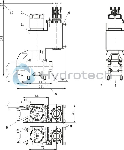
2/2 and 3/2 directional seat valve
Dimensions in mm
|
|
Required surface quality of the valve contact surface |
|
1 |
Solenoid coil |
|
2 |
Concealed manual override “N9” |
|
3 |
Mounting nut with hexagon SW32 |
|
4 |
Terminal box |
|
5 |
Identical seal rings for ports A, B, and T; seal ring for port P |
|
6 |
Name plate |
|
7 |
Valve mounting screws (included within the scope of delivery) For reasons of stability, exclusively use the following valve mounting screws: 4 hexagon socket head cap screws ISO 4762-M5 x 45-10.9-flZn-240h-L (friction coefficient μtotal = 0.09 … 0.14) |
|
8 |
Notice With 3/2 directional seat valves, port B is designed as blind counterbore. With 2/2 directional seat valves, ports A and B are designed as blind counterbores. |
|
9 |
Porting pattern according to ISO 4401-03-02-0-05 (but without locating hole) |
|
10 |
Space required to remove the solenoid coil |
Subplates (separate order) with porting pattern according to ISO 4401-03-02-0-05, see data sheet 45100.
Notice:
Subplates are no components in the sense of directive 2014/34/EU and can be used after the manufacturer of the overall system has conducted an assessment of the risk of ignition.
The "G...J3" versions are free from aluminum and/or magnesium and galvanized.
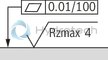
4/2 directional seat valve
Dimensions in mm
|
|
|
Required surface quality of the valve contact surface |
|
1 |
Solenoid coil |
|
2 |
Concealed manual override “N9” |
|
3 |
Mounting nut with hexagon SW32 |
|
4 |
Terminal box |
|
5 |
Identical seal rings for ports A, B, and T; seal ring for port P |
|
6 |
Name plate |
|
7 |
Valve mounting screws (included in the scope of delivery) |
|
8 |
Plus-1 plate |
|
9 |
Porting pattern according to ISO 4401-03-02-0-05 (but without locating hole) |
|
10 |
Space required to remove the solenoid coil |
Subplates (separate order) with porting pattern according to ISO 4401-03-02-0-05, see data sheet 45100.
Notice:
Subplates are no components in the sense of directive 2014/34/EU and can be used after the manufacturer of the overall system has conducted an assessment of the risk of ignition.
The "G...J3" versions are free from aluminum and/or magnesium and galvanized.
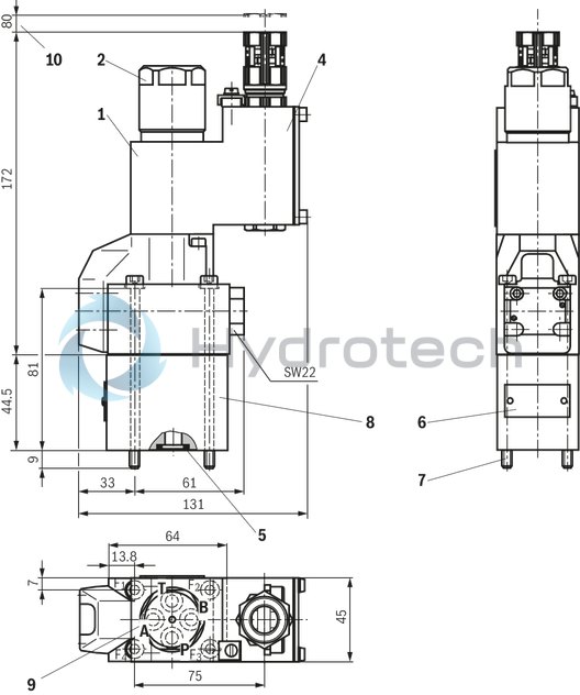
Installation conditions (dimensions in mm)
|
Individual assembly |
Bank assembly |
|
|
Subplate dimensions |
Minimum dimensions: |
Minimum cross-section: |
|
Thermal conductivity of the subplate (EN-GJS-500-7) |
≥ 38 W/mK |
|
|
Minimum distance between the longitudinal valve axes |
≥ 55 |
|
Schematic diagram
Dimensions in mm
Notice:
Observe the “Special application conditions for a safe application” in chapter "Technical data".