
BOSCH REXROTH
KKDER8PA/HN9V
R901069978
Directional Spool Valves
Sv st do 3/2 SZ08 SAE Std no opt
BOSCH REXROTH
MATERIAL: R901069978
SUMMARY: Sv st do 3/2 SZ08 SAE Std no opt
Due to extremely high demand, please call 888-651-5712 for availability
General information
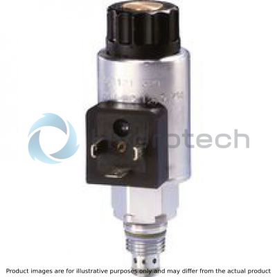
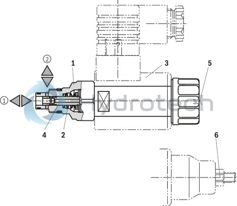
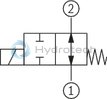
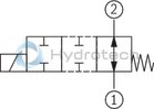
The 2/2 directional spool valves are direct operated, pressure-compensated screw-in cartridge valves. They control the start, stop and direction of flow and basically consist of housing (1), control spool (4) and a return spring (2).
Function
In the de-energized condition, the control spool (4) is held in the initial position by the return spring (2). The control spool (4) is actuated by wet-pin DC solenoids (3). The symbols are realized by different spools (N and P). The main ports ➀ and ➁ can be loaded continuously with an operating pressure of 350 bar and the flow can be directed into both directions (see Symbols).
The manual override (5) allows for the switching of the valve without solenoid energization. It is also available in screwable version"N10" (6) (see Type keys).
Version "K4" (with mating connector)
Type KKDER8NA/HN9V
Version "C4"
(valve without coil)1)
|
01 |
02 |
03 |
04 |
05 |
06 |
07 |
08 |
09 |
|
|
KKDE |
R |
8 |
A |
/ |
H |
V |
* |
|
01 |
Directional spool valve, direct operated, electrically operated (pilot valve) |
KKDE |
|
|
02 |
Maximum operating pressure 350 bar |
R |
|
|
03 |
Component size |
8 |
|
|
04 |
2 main ports |
||
|
Symbols |
 |
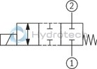 |
N |
 |
 |
P |
|
|
05 |
Component series |
A |
|
|
06 |
High Performance and mounting cavity R/T-8A (see mounting cavity) |
H |
|
|
07 |
Without manual override |
N0 |
|
|
With concealed manual override 2) |
N9 |
||
|
Seal material |
|||
|
08 |
FKM seals (other seals upon request) |
V |
|
|
Observe compatibility of seals with hydraulic fluid used. (Other seals upon request) |
|||
|
09 |
Further details in the plain text |
* |
|
| 1) Complete valves with mounted coil on request. | |
2) Screwable manual override "N10" (actuation by means of internal hexagon with lock nut), can be ordered separately, material no. R901051231; ordering code “N9”!
general
|
Size |
8 | ||
|
Installation position |
any | ||
|
Ambient temperature range |
°C |
-40 … +110 | |
|
Weight |
Valve |
kg |
0.3 |
|
Coil |
kg |
0.25 | |
hydraulic
|
Size |
8 | |
|
Maximum operating pressure 1) |
bar |
350 |
|
Maximum flow |
l/min |
45 |
|
Hydraulic fluid |
see table | |
|
Hydraulic fluid temperature range |
°C |
-40 … +80 |
|
Viscosity range |
mm²/s |
4 … 500 |
|
Maximum admissible degree of contamination of the hydraulic fluid 2) |
Class 20/18/15 according to ISO 4406 (c) | |
|
Fatigue strength according to ISO 10771 |
10 million (at 350 bar) | |
| 1) | At all ports |
| 2) | The cleanliness classes specified for the components must be adhered to in hydraulic systems. Effective filtration prevents faults and simultaneously increases the life cycle of the components. For the selection of the filters, see www.boschrexroth.com/filter. |
|
Hydraulic fluid |
Classification |
Standards |
|
|
Mineral oil |
HL, HLP |
DIN 51524 |
|
|
Bio-degradable |
Insoluble in water |
HEES (synthetic esters) |
VDMA 24568 |
|
HETG (rape seed oil) |
|||
|
Soluble in water |
HEPG (polyglycols) |
VDMA 24568 |
|
|
Other hydraulic fluids on request |
|||
electrical
|
Voltage type |
Direct voltage | ||
|
Power supply 1) |
V |
12 24 |
|
|
Voltage tolerance against ambient temperature |
see voltage tolerance characteristic curve | ||
|
Power consumption |
W |
22 | |
|
Duty cycle |
% |
100 | |
|
Maximum coil temperature 2) |
°C |
150 | |
|
Switching time according to ISO 6403 |
ON |
ms |
≤ 80 |
|
OFF |
ms |
≤ 50 | |
|
Maximum switching frequency |
1/h |
15000 | |
|
Protection class according to DIN EN 60529 (VDE 0470-1), DIN 40050-9 |
Version "K4" |
IP65 (with mating connector mounted and locked) | |
|
Version "C4" |
IP66 with mating connector mounted and locked IP69K with Rexroth mating connector (material no. R901022127) |
||
|
Version "K40" |
IP69K with mating connector mounted and locked | ||
| 1) | Other voltages upon request |
| 2) | Due to the surface temperatures of the solenoid coils, the standards ISO 13732-1 and EN 982 need to be adhered to! |
With the electrical connection "K4", the protective earthing conductor (PE, grounded) is to be connected in accordance with the stipulations.
For applications outside these parameters, please consult us!
Voltage tolerance against ambient temperature; duty cycle
Voltage range and duty cycle dependent on the ambient temperature
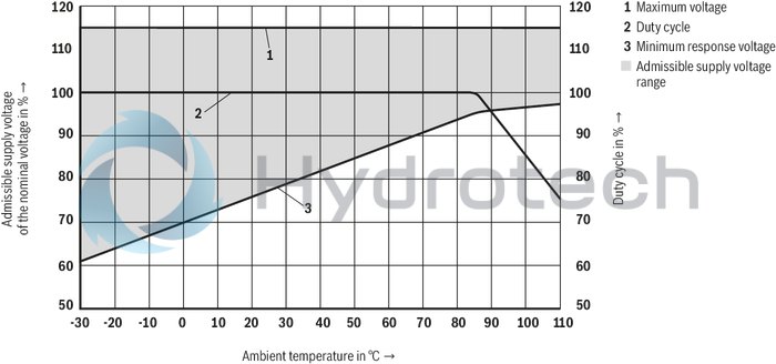
(measured with HLP46, ϑoil = 40 ±5 °C) and 24 V coil
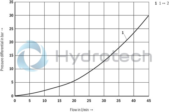
Δp-qV characteristic curves – Symbol N
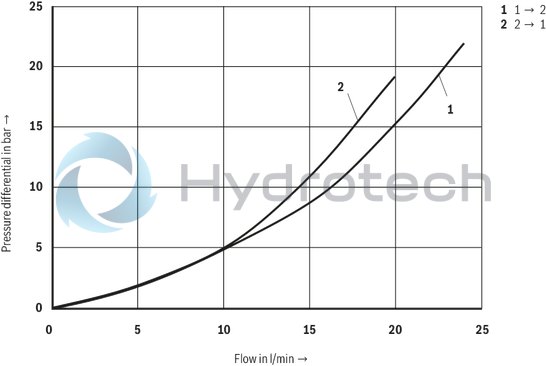
Δp-qV characteristic curves – Symbol P
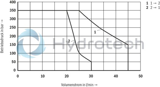
Performance limits (measured with HLP46, ϑOil = 40 ±5 °C and 24 V coil)
Symbol N
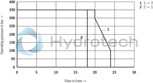
Symbol P
Attention!
The performance limit has been determined with the solenoids at operating temperature and with 10 % undervoltage.
Symbol “N”
Symbol “P”
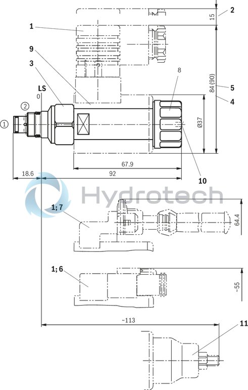
Dimensions in mm
|
1 |
Mating connectors (separate order) |
|
2 |
Space required to remove the mating connector |
|
3 |
Wrench size 24, tightening torque MA = 34 to 41 Nm |
|
4 |
Dimension for mating connector “K4”, without circuitry |
|
5 |
Dimension () for mating connector “K4”, with circuitry |
|
6 |
Version "K40" |
|
7 |
Version "C4" |
|
8 |
Nut, tightening torque MA = 5+1 Nm |
|
9 |
Coil (separate order, see type key) |
|
10 |
Concealed manual override "N9", optional |
|
11 |
Screwable manual override "N10" (separate order, see Type keys) |
|
➀ |
Main port 1 |
|
➁ |
Main port 2 |
|
LS |
Location shoulder |
Mounting cavity R/T-8A; 2 main ports; thread M16 x 1.5 mm
Dimensions in mm
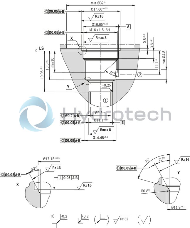
1) with counterbore, deviating from T-8A
2) All seal ring insertion faces are rounded and free of burrs
3) deviating from T-8A
|
➀ |
Main port 1 |
|
➁ |
Main port 2 |
|
LS |
Location shoulder |
|
Tolerance for all angles ± 0.5 ° |
|
Mating connectors for directional valves with connector "C4" and "C4Z" (AMP Junior-Timer), litz wire outer diameter 2.2 mm to 3.0 mm
2P JUNIOR D2 2

Mating connectors for directional valves with connector "C4" and "C4Z" (AMP Junior-Timer), litz wire outer diameter 2.2 mm to 3.0 mm
2P JUNIOR D2 2
For directional valves with connector "C4" and "C4Z" (AMP Junior-Timer)Data sheet
Spare parts & repair