
BOSCH REXROTH
4WRZ32W6-520-7X/6EG24XEJ/D3V
R901149529
Proportional Directional Valves
Prop. dir. valves: WRZ* 32.-7x/
BOSCH REXROTH
MATERIAL: R901149529
SUMMARY: Prop. dir. valves: WRZ* 32.-7x/
Quantity in stock: 0
Pilot control valve, type 3DREP 6…
The pilot control valve is a 3-way pressure reducing valve that is actuated by a proportional solenoid. It converts an electrical input signal into a proportional pressure output signal and is used for all valves type 4WRZ...
The proportional solenoids are controllable wet-pin DC solenoids. The solenoids are controlled by external control electronics.
Set-up:
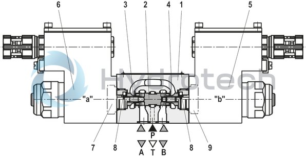
The valve basically consists of:
Housing (1) with connection surface Control spool (2) with pressure measuring pins (3 and 4) Solenoids (5 and 6) with central threadFunction:
The pressure in A or B is set by means of the proportional solenoids. The amount of the pressure depends on the current.
With de-energized solenoids (5, 6), the control spool (2) is held in the central position by means of the compression springs (8). Ports A and B are connected with T so that the hydraulic fluid can flow off to the tank without obstructions.
By actuating a proportional solenoid, e.g. solenoid "b" (5), the pressure measuring pin (4) and the control spool with it (2) are moved to the left. This opens the connection from P to A and B to T via orifice-type cross-sections with progressive flow characteristics. With the surface of the pressure measuring pin (3) the pressure that builds up in channel A acts on the control spool and against the solenoid force. The pressure measuring pin (3) is supported by the solenoid "a". If the pressure exceeds the value set at solenoid “b”, the control spool (2) is pushed back against the solenoid force and connects A with T until the set pressure is achieved again. The pressure is proportional to the solenoid current.
When the solenoid is switched off, the control spool (2) is returned to the central position by the compression springs (8).
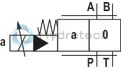
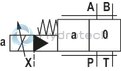
Valve with two spool positions
(Version “3DREP 6…A…” and “3DREP 6…B…”)
The function of this valve version basically corresponds to the valve with three spool positions. This 2 spool position valve is, however, only equipped with solenoid “b” ((5); version “A”) or solenoid “a” ((6); version “B”). Instead of the 2nd proportional solenoid, there is a plug screw (7 or 9).
Notes:
Regarding valves of the version “3DREP 6 C”, only one solenoid may be actuated at a time. The tank line must not be allowed to run empty. With corresponding installation conditions, a preload valve (preload pressure approx. 2 bar) must be installed.Type 3DREP 6..2X/..XE…
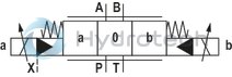
Pilot-operated proportional directional valve type, 4WRZ …XE...
Valves of the type 4WRZ... are pilot-operated 4-directional valves that are actuated by means of proportional solenoids. Their function is to control the flow direction and size.
Set-up:
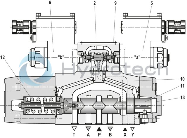
The valve basically consists of:
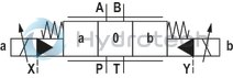
Pilot control valve (9) with proportional solenoids (5 and 6) Main valve (10) with main control spool (11) and centering spring (12)Function:
With de-energized solenoids (5 and 6), the main control spool (11) is held in central position by means of a centering spring (12) The main control spool (11) is controlled by the pilot control valve (9); the main control spool is proportionally moved, e.g. by actuating solenoid "b" (6) The control spool (2) is moved to the right, pilot oil enters the pressure chamber (13) via the pilot control valve (9) and deflects the main control spool (11) proportionally to the electric input signal to the left Connection from P → A and B → T via orifice-type cross-sections with progressive flow characteristic Pilot oil supply to the pilot control valve internally via port P or externally via port X Switching off the solenoid (6) The control spool (2) and main control spool (11) are moved back into the central position Flow depending on spool position from P → A and B → T or P → B and A → T.Type 4WRZ...-7X./...
|
01 |
02 |
03 |
04 |
05 |
06 |
07 |
08 |
09 |
10 |
11 |
12 |
13 |
|||
|
4WR |
Z |
‒ |
7X |
/ |
6E |
G24 |
XE |
J |
/ |
D3 |
|
Main ports |
||
|
01 |
Proportional directional valve |
4WR |
|
Type |
||
|
02 |
Electro-hydraulic actuation |
Z |
|
Size |
||
|
03 |
Size 10 |
10 |
|
Size 16 |
16 |
|
|
Size 25 |
25 |
|
|
Size 32 |
32 |
|
|
Control spool |
||
|
04 |
Symbols e. g. E, E3-, W6- etc.; possible version see circuit diagrams |
|
|
Nominal flow |
||
|
05 |
Size 10 |
|
|
25 l/min |
25 |
|
|
50 l/min |
50 |
|
|
85 l/min |
85 |
|
|
Size 16 |
||
|
100 l/min |
100 |
|
|
125 l/min |
125 |
|
|
150 l/min |
150 |
|
|
180 l/min |
180 |
|
|
Size 25 |
||
|
220 l/min |
220 |
|
|
325 l/min |
325 |
|
|
Size 32 |
||
|
360 l/min |
360 |
|
|
520 l/min |
520 |
|
|
Component series |
||
|
06 |
Component series 70 … 79 (70 … 79: unchanged installation and mounting dimensions) |
7X |
|
Solenoid |
||
|
07 |
Proportional solenoid |
6E |
|
Supply voltage of the control electronics |
||
|
08 |
Direct voltage 24 V |
G24 |
|
Explosion protection |
||
|
09 |
“Increased safety”, for details, please refer to the "information on explosion protection" |
XE |
|
Corrosion resistance (outside) |
||
|
10 |
Seawater-resistant, galvanized |
J |
|
Pilot oil supply and return |
||
|
11 |
External pilot oil supply, external pilot oil return |
no code |
|
Internal pilot oil supply, external pilot oil return |
E |
|
|
Pilot oil supply internal, pilot oil return internal |
ET |
|
|
External pilot oil supply, internal pilot oil return |
T |
|
|
12 |
With pressure reducing valve (fixedly set) |
D3 |
|
13 |
NBR seals |
M |
|
FKM seals |
V |
|
|
Observe compatibility of seals with hydraulic fluid used. |
||
For applications outside these parameters, please consult us!
general
|
Type |
4WRZ...XE | ||||
|
Size |
10 | 16 | 25 | 32 | |
|
Installation position |
any, preferably horizontal | ||||
|
Ambient temperature range |
°C |
-20 … +60 | |||
|
Storage temperature range |
°C |
+5 … +40 | |||
|
Maximum storage time |
Years |
see operating instructions 29115-XE | |||
|
Weight |
kg |
10 | 16 | 21 | 45 |
|
Surface protection |
Galvanized | ||||
hydraulic
|
Size |
10 | 16 | 25 | 32 | |||
|
Maximum operating pressure |
bar |
315 | 350 | ||||
|
Operating pressure range |
External pilot oil supply |
bar |
30 … 100 | ||||
|
Internal pilot oil supply |
bar |
100 … 315 | 100 … 350 | ||||
|
Maximum return flow pressure |
Port T, external pilot oil return |
bar |
315 | 250 | 150 | ||
|
Port T, internal pilot oil return |
bar |
30 | |||||
|
Port Y |
bar |
30 | |||||
|
Pilot flow |
Eingangssignal 0 → 100% |
Port X and Y |
l/min |
3.5 | 5.5 | 7 | 15.9 |
|
Pilot volume |
Schaltvorgang 0 → 100% |
cm³ |
1.7 | 4.6 | 10 | 26.5 | |
|
Maximum flow of the main valve |
l/min |
170 | 460 | 870 | 1600 | ||
|
Hydraulic fluid |
see table | ||||||
|
Hydraulic fluid temperature range |
NBR seals |
°C |
-20 … +80 | ||||
|
FKM seals |
°C |
-15 … +80 | |||||
|
Viscosity range |
mm²/s |
20 … 380 | |||||
|
preferably |
mm²/s |
30 … 46 | |||||
|
Maximum admissible degree of contamination of the hydraulic fluid, cleanliness class according to ISO 4406 (c) 1) |
Pilot control valve |
Class 17/15/12 according to ISO 4406 (c) | |||||
|
Main valve |
Class 18/16/13 according to ISO 4406 (c) | ||||||
|
Hysteresis |
% |
≤ 6 | |||||
|
Maximum surface temperature |
°C |
120 | |||||
| 1) | The cleanliness classes specified for the components must be adhered to in hydraulic systems. Effective filtration prevents faults and simultaneously increases the life cycle of the components. For the selection of the filters, see www.boschrexroth.com/filter. |
|
Hydraulic fluid |
Classification |
Suitable sealing materials |
Standards |
Data sheet |
|
|
Mineral oils |
HL, HLP, HLPD, HVLP, HVLPD |
NBR, FKM |
DIN 51524 |
90220 |
|
|
Bio-degradable 1) |
Insoluble in water |
HETG |
FKM |
ISO 15380 |
90221 |
|
HEES |
FKM |
||||
|
Soluble in water |
HEPG |
FKM |
ISO 15380 |
||
|
Flame-resistant 1) |
Water-free |
HFDU, HFDR |
FKM |
ISO 12922 |
90222 |
|
Containing water |
HFC (Fuchs Hydrotherm 46M, Petrofer Ultra Safe 620 ) |
NBR |
ISO 12922 |
90223 |
|
|
Important information on hydraulic fluids: For further information and data on the use of other hydraulic fluids, please refer to the data sheets above or contact us. There may be limitations regarding the technical valve data (temperature, pressure range, life cycle, maintenance intervals, etc.). The ignition temperature of the hydraulic fluid used must be 50 K higher than the maximum solenoid surface temperature.Flame-resistant – containing water: Maximum operating pressure 210 bar Maximum pressure differential per control edge 175 bar Pressure pre-loading at the tank port > 20% of the pressure differential, otherwise increased cavitation erosion Life cycle as compared to operation with mineral oil HL, HLP 50 … 100% Maximum hydraulic fluid temperature 50 °CBio-degradable and flame-resistant: If these hydraulic fluids are used which are also zinc-solving, an accumulation of zinc may occur. |
|||||
| 1) | Not recommended for corrosion-protected version "J" |
electrical
|
Size |
10 | 16 | 25 | 32 | ||
|
Voltage type |
Direct current or pulse-width modulated signal with a pulse voltage ≤ 28 V and a frequency ≥ 160 Hz up to max. 500 Hz | |||||
|
Type of signal |
analog | |||||
|
Maximum solenoid current |
A |
1.03 | ||||
|
Actuated time |
% |
100 | ||||
|
Maximum coil temperature |
°C |
120 | ||||
Control electronics
|
Amplifier module for the control of explosion-proof proportional directional valves 4WRA...XE, 3DREP 6...XE and 4WRZ...XE |
VT-MSPA2-200-1X/V0/0 according to data sheet 30228-200 |
|
Module for monitoring and limiting the solenoid currents with proportional valves |
VT-MUXA2-2-1X/V0/1A according to data sheet 30290 |
|
Notice: |
|
Information on explosion protection
|
Application according to Explosion Protection Directive 2014/34/EU |
II 2G |
|
Type of protection of the valve according to EN 13463-1/ EN 13463-5 |
c T4 X |
|
Valve solenoid type of protection according to EN 60079-7 / EN 60079-18 1) |
Ex eb mb IIC T4 Gb |
|
Type examination certificate solenoid |
KEMA 02ATEX2240 X |
|
“IECEx Certificate of Conformity” for solenoid |
IECEx DEK 12.0068X |
|
Special application conditions for a safe application |
– In case of bank assembly, only one solenoid of all valves may be energized at a time. ‒ In case of valves with two solenoids, only one of the solenoids may be energized at a time. ‒ Only direct current or a pulse-width modulated signal with a pulse voltage ≤ 28 V and frequency ≥ 160 Hz up to max. 500 Hz may be used. |
| 1) | Surface temperature > 50 °C, provide contact protection. |
Control electronics
|
Amplifier module for the control of explosion-proof proportional directional valves 4WRA...XE, 3DREP 6...XE and 4WRZ...XE |
VT-MSPA2-200-1X/V0/0 according to data sheet 30228-200 |
|
Module for monitoring and limiting the solenoid currents with proportional valves |
VT-MUXA2-2-1X/V0/1A according to data sheet 30290 |
|
Notice: |
|
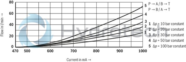
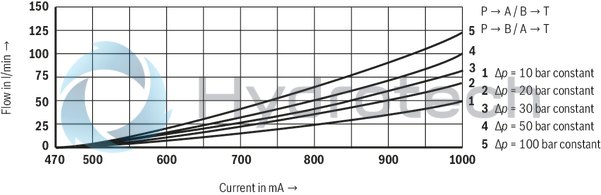
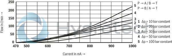
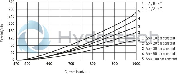
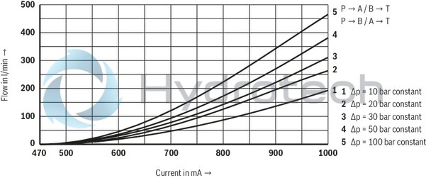
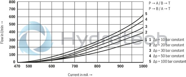
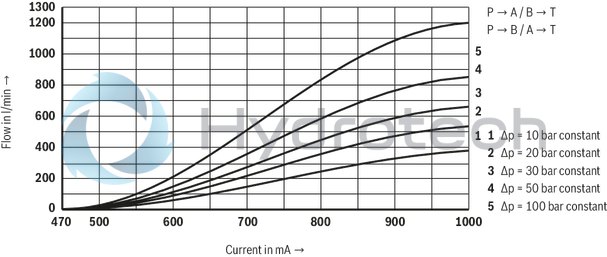
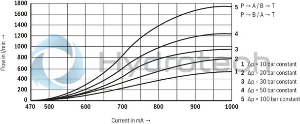
(measured with symbol E, W6-, EA, W6A, HLP46, ϑOil = 40 ±5 °C)
Size 10
Rated flow 25 l/min
Size 10
Rated flow 50 l/min
Size 10
Rated flow 85 l/min
Size 10
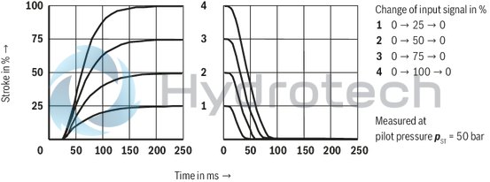
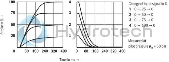
Transition function with stepped electric input signals
Size 16
Rated flow 100 l/min
Size 16
Rated flow 125 l/min
Size 16
Rated flow 150 l/min
Size 16
Rated flow 180 l/min
Size 16
Transition function with stepped electric input signals
Size 25
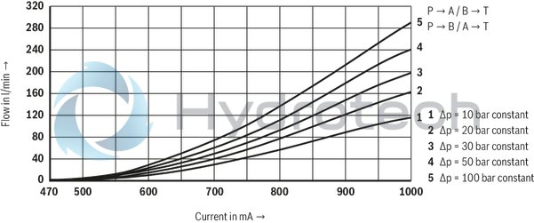
Rated flow 220 l/min
Size 25
Rated flow 325 l/min
NG25
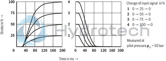
Transition function with stepped electric input signals
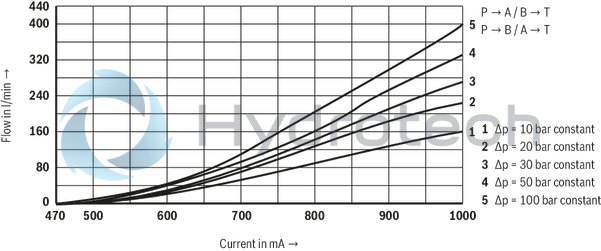
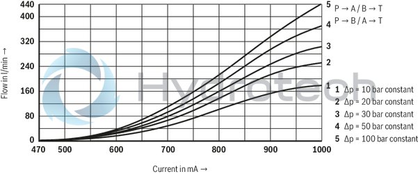
Size 32
Rated flow 360 l/min
Size 32
Rated flow 520 l/min
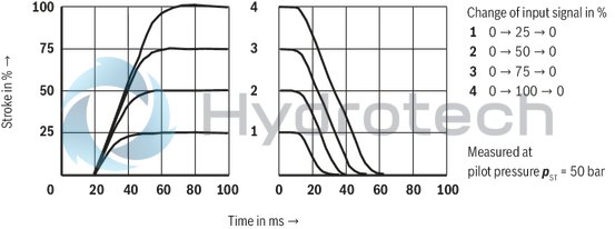
Size 32
Transition function with stepped electric input signals
|
Δp = pP – pL – pT (according to DIN 24311) |
|
|
Δp |
Valve pressure differential |
|
pP |
Inlet pressure |
|
pL |
Load pressure |
|
pT |
Return flow pressure |
(measured with HLP46, ϑÖl = 40 ±5 °C)
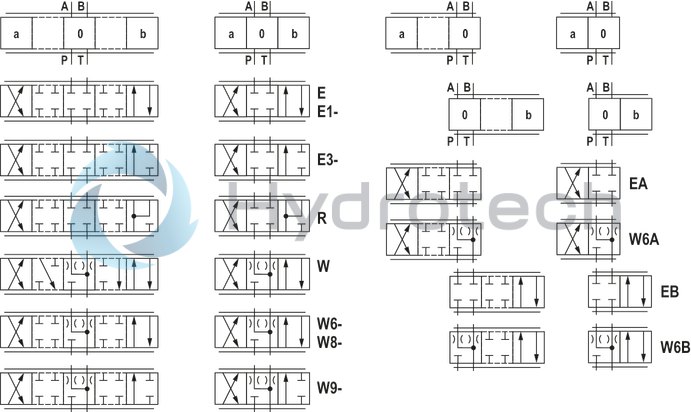
Symbols
|
With symbols E1- and W8-, the following applies: |
|
|
P → A: qvmax |
B → T: qv/2 |
|
P → B: qv/2 |
A → T: qvmax |
|
With symbols E3- and W9-, the following applies: |
|
|
P → A: qvmax |
B → T: blocked |
|
P → B: qv/2 |
A → T: qvmax |
|
(Differential circuit, piston top at port A) |
|
|
Notice: |
|
Pilot oil supply
|
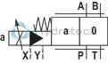
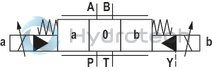
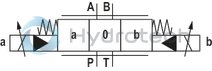
3 Switching positions |
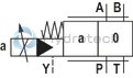
2 Switching positions (Version ".A)" |
|
 |
 |
Type 4WRZ …
External pilot oil supply, external pilot oil return The pilot oil is supplied from a separate control circuit (external). The pilot oil return is not directed into channel T of the main valve, but is separately directed to the tank via port Y (external). |
 |
 |
Type 4WRZ …E…
Internal pilot oil supply, external pilot oil return
The pilot oil supply is implemented from channel P of the main valve (internally). The pilot oil return is not directed into channel T of the main valve, but is separately directed to the tank via port Y (external). In the subplate, port X is to be closed. |
 |
 |
Type 4WRZ …ET…
Internal pilot oil supply; internal pilot oil return
The pilot oil supply is implemented from channel P of the main valve (internally). The pilot oil is directly returned to channel T of the main valve (internally). In the subplate, ports X and Y are to be closed. |
 |
 |
Type 4WRZ …T…
External pilot oil supply, internal pilot oil return
The pilot oil is supplied from a separate control circuit (external). The pilot oil is directly returned to channel T of the main valve (internally). In the subplate, port Y is to be closed. |
The type-examination tested valve solenoid of the valve is equipped with one terminal box and a type-tested cable entry.
The connection is polarity-independent.
Notice:
When establishing the electrical connection, the protective earthing conductor PE has to be connected properly.

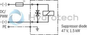
| 1) |
Recommended pre-fusecharacteristics: medium time-lag according to DIN 41571; 1.25 A |
Properties of the connection terminals and mounting elements
|
Position |
Function |
Connectable line cross-section |
|
1 |
Operating voltage connection |
Single-wire 0.75 … 2.5 mm2 |
|
Finely stranded,0.75 … 1.5 mm2 |
||
|
2 |
Connection for protective earthing conductor |
Single-wire 2.5 mm2 max. |
|
Finely stranded, 1.5 mm2 max. |
||
|
3 |
Connection for potential equalization conductor |
Single-wired, 4 … 6 mm2 |
|
Finely stranded, 4 mm2 |
Cable gland
|
Type approval |
II 2G Ex e IIC Gb |
|
Threaded connection |
M20 x 1,5 |
|
Protection class according to DIN EN 60529 |
IP66 (with correctly installed electrical connection) |
|
Line diameter |
7 … 10,5 mm |
|
Sealing |
Outer sheath sealing |
Connection line
|
Line type |
Non-armored cables and lines (outer sheath sealing) |
|
Temperature range |
–30 … > +110 °C |
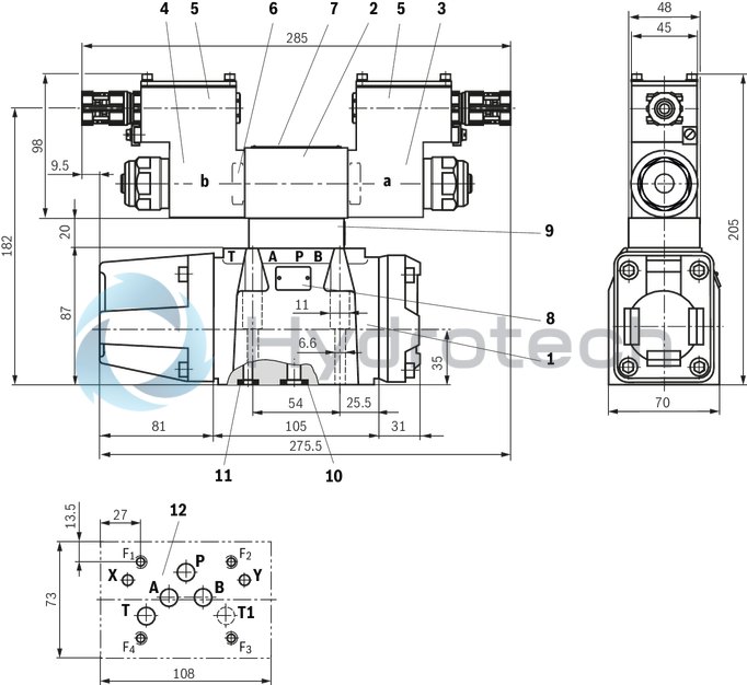
Size 10
Dimensions in mm
 |
|
Required surface quality of the valve contact surface |
|
1 |
Main valve |
|
2 |
Pilot control valve |
|
3 |
Proportional solenoid "a" |
|
4 |
Proportional solenoid "b" |
|
5 |
Terminal box |
|
6 |
Plug screw for valve with one solenoid |
|
7 |
Name plate pilot control valve |
|
8 |
Name plate main valve |
|
9 |
Pressure reducing valve (always available) |
|
10 |
Identical seal rings for ports P, A, B, T and T1 |
|
11 |
Identical seal rings for ports X and Y |
|
12 |
Machined valve contact surface; Porting pattern according to ISO 4401-05-05-0-05 (ports X and Y as required, T1 is available at the valve and can optionally be provided) |
Valve mounting screws (separate order):
For reasons of stability, exclusively the following valve mounting screws are to be used:
4 hexagon socket head cap screws
ISO 4762 - M6 x 45 - 10.9-CM-Fe-ZnNi-5-Cn-T0-H-B
(friction coefficient μtotal = 0.09 … 0.14)
Tightening torque MA = 13 Nm ±10 %,
material no. R913043777
Subplates (separate order) with porting pattern according to ISO 4401-05-05-0-05, see data sheet 45100.
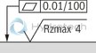
Size 16
Dimensions in mm
|
|
|
Required surface quality of the valve contact surface |
|
1 |
Main valve |
|
2 |
Pilot control valve |
|
3 |
Proportional solenoid "a" |
|
4 |
Proportional solenoid "b" |
|
5 |
Terminal box |
|
6 |
Plug screw for valve with one solenoid |
|
7 |
Name plate pilot control valve |
|
8 |
Name plate main valve |
|
9 |
Pressure reducing valve (always available) |
|
10 |
Identical seal rings for ports A, B, P, and T (not with version “100” and “150”) |
|
11 |
Identical seal rings for ports X and Y |
|
12 |
Machined valve contact surface; Porting pattern according to ISO 4401-07-07-0-05 (ports X and Y as required) |
|
13 |
Locating pin |
Valve mounting screws (separate order):
For reasons of stability, exclusively the following valve mounting screws are to be used:
2 hexagon socket head cap screws
ISO 4762 - M6 x 60 - 10.9-CM-Fe-ZnNi-5-Cn-T0-H-B
(friction coefficient μtotal = 0.09 … 0.14)
Tightening torque MA = 12.2 Nm ±10 %,
material no. R913043410
4 hexagon socket head cap screws ISO 4762 - M10 x 60 - 10.9-flZn/nc/480h/C
(friction coefficient μtotal = 0.09 … 0.14)
Tightening torque MA = 58 Nm ±20 %,
material no. R913014770
Subplates (separate order) with porting pattern according to ISO 4401-07-07-0-05, see data sheet 45100.
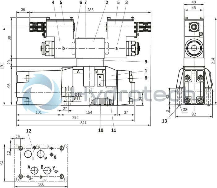
Size 25
Dimensions in mm
|
|
|
Required surface quality of the valve contact surface |
|
1 |
Main valve |
|
2 |
Pilot control valve |
|
3 |
Proportional solenoid "a" |
|
4 |
Proportional solenoid "b" |
|
5 |
Terminal box |
|
6 |
Plug screw for valve with one solenoid |
|
7 |
Name plate pilot control valve |
|
8 |
Name plate main valve |
|
9 |
Pressure reducing valve (always available) |
|
10 |
Identical seal rings for ports A, B, P, and T |
|
11 |
Identical seal rings for ports X and Y |
|
12 |
Machined valve contact surface; Porting pattern according to ISO 4401-08-08-0-05 (ports X and Y as required) |
|
13 |
Locating pin |
Valve mounting screws (separate order):
For reasons of stability, exclusively the following valve mounting screws are to be used:
6 hexagon socket head cap screws ISO 4762 - M12 x 60 - 10.9-flZn/nc/480h/C
(friction coefficient μtotal = 0.09 … 0.14)
Tightening torque MA = 100 Nm ±20 %,
material no. R913015613
Subplates (separate order) with porting pattern according to ISO 4401-08-08-0-05 see data sheet 45100.
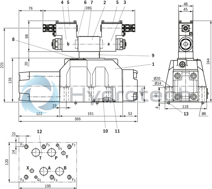
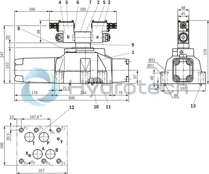
Size 32
Dimensions in mm
|
|
|
Required surface quality of the valve contact surface |
|
1 |
Main valve |
|
2 |
Pilot control valve |
|
3 |
Proportional solenoid "a" |
|
4 |
Proportional solenoid "b" |
|
5 |
Terminal box |
|
6 |
Plug screw for valve with one solenoid |
|
7 |
Name plate pilot control valve |
|
8 |
Name plate main valve |
|
9 |
Pressure reducing valve (always available) |
|
10 |
Identical seal rings for ports A, B, P, and T |
|
11 |
Identical seal rings for ports X and Y |
|
12 |
Machined valve contact surface; Porting pattern according to ISO 4401-10-09-0-05 (Ports X and Y as required) |
|
13 |
Locating pin |
Valve mounting screws (separate order):
For reasons of stability, exclusively the following valve mounting screws are to be used:
6 hexagon socket head cap screws ISO 4762 - M20 x 80 - 10.9-flZn/nc/480h/C
(friction coefficient μtotal = 0.09 … 0.14)
Tightening torque MA = 340 Nm ±20 %,
Material no. R913008472
Subplates (separate order) with porting pattern according to ISO 4401-10-09-0-05 see data sheet 45100.