
BOSCH REXROTH
VT-HACD-3-2X/0-I-00/000
R901239533
Controller Test Rigs
Digital controller HACD.2X
BOSCH REXROTH
MATERIAL: R901239533
SUMMARY: Digital controller HACD.2X
Quantity in stock: 0
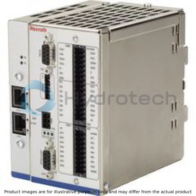
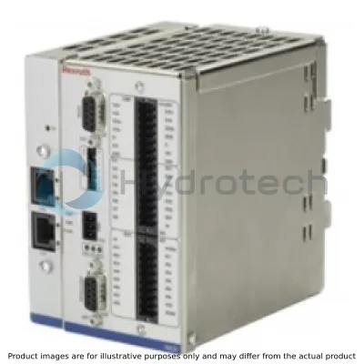
The VT-HACD-3-2X control electronics are a module for top hat rail mounting.
A microcontroller controls the entire process, makes adjustments, establishes connections and realizes the closed control loops. Data for configuration, command values and parameters are stored in a FLASH in a non-volatile form.
The BODAC PC program is used for the entire configuration and also for the parameterization and diagnosis. Besides the switches for address setting, the module is not equipped with any additional hardware switches. For the configuration, the HACD has to be connected to a PC via a serial interface (RS 232, 1:1 cable).
The configuration and thus the creation of applications are very simple - simply connect the pre-defined functional components. For this purpose, no programming knowledge is necessary.
A mode is available:
Structural editorOwn motion sequences can be established. For this purpose, 32 blocks are available.
Each block contains: Command value, ramp times, (velocity ±, acceleration ±) and controller parameters.
Blocks are activated by setting trigger conditions: Setting digital inputs, comparing signals with freely definable thresholds or expiry of waiting times.
Signal linking [6] [8] [17]
The HACD has various signal linking options both for the input and the output side, whereas 2 signals each can be linked. These are functions such as addition, subtraction, multiplication, division as well as minimum/maximum value generator, area ration and limiter:
+ = Addition: Z = X + Y
– = Subtraction: Z = X – Y
* = Multiplication: Z = X * Y / 100
/ = Division: Z = X / Y * 100
MIN = Minimum value generator: Z = MIN (X, Y)
MAX = Maximum value generator: Z = MAX (X, Y)
RATIO = Ratio input:
for RATIO >1: Z = X * RATIO – Y
for RATIO <1: Z = X – Y / RATIO
(e.g. area ratio for pressure differential measurement)
LIMIT = Signal limiter: Z = MIN (|X|, |Y|) * sign (X)
JUMP = Jump generator: Z = MAX (|X|, |Y|) * sign (X)
with Z … result
X … 1st signal
Y … 2nd signal
T1 Lag = Low pass filter
Analog I/O [1] [15]
The 6 analog inputs are switchable between ±10 V, 0…10 V, 0…20 mA by means of the software.
The analog output AO1 is switchable between ±10 V, 0…10 V, 0…20 mA and 4…20 mA by means of the software.
AO2 and AO3 are fixedly set to ±10 V.
The output is switched so that the whole range of the analog-digital converter is used.
Both working range and error detection can be defined for all analog inputs.
The analog outputs can be adjusted by means of amplification and offset.
Digital I/O [3] [16]
The HACD has 9 digital inputs and 8 digital outputs.
An input has the fix functionality Enable, a digital output the fixed functionality OK.
Further digital inputs are used for the triggering of blocks (see blocks and triggering).
The function of each digital output can be determined by the selection from a predefined list:
Command value = actual value Actual value higher or lower than the adjustable threshold Waiting time completed Ramp active internal flag set Error flag set Table completed Error status Block timeout Controller active Absolute value (actual value) < window Absolute value (command value) < window Incremental home position
Digital position measurement system
If VT-HACD-3-2X is used as control electronics, digital position measurement systems of type SSI or incremental can be used for actual value recording.
Limitations of use for the incremental encoder
The maximum frequency of the HACD incremental encoder input (fG) is 250 kHz. The maximum travel velocity of the drive, the resolution (res) of the encoder system used and the possible signal evaluation by EXE (interpolation and digitalizing electronics) determine the frequency.
Determination formulas
Encoder resolution at given maximum velocity:

Velocity at specified encoder resolution:

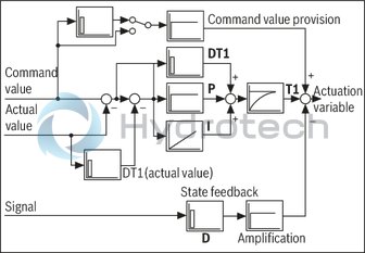
Controller
If the HACD is used as control electronics, select "Controller" for signal linking [8].
The LCx signals indicate the command value branch, the LFBx signals indicate the actual value branch. [8]
Both SSI encoder or incremental encoder [2] (digital measurement system) and one or more analog sensors can be used as actual value signal.
The controller structure is designed as PIDT1 controller, whereas each share can be activated or deactivated individually. Thus, also a P or PT1 controller can be implemented for example. The I share can additionally be controlled via a window (upper and lower limit).
Control parameters can be set in blocks or independently of blocks.
A state feedback can be used for controller output damping.
Controller structure:
Adjustment to hydraulic system
For the optimum adjustment to the particularities of hydraulic drives, the following functions are implemented upstream the analog output:
Direction-dependent amplification [10]For positive and negative values, the amplification can be set separately. In this way, adjustment to the area ratio of a differential cylinder is possible.
Characteristic curve correction [11]In this way, the progressive flow characteristics of proportional directional valves are compensated or an inflected characteristic curve is realized.
Overlap jump/residual velocity [12]When using valves with positive overlap, a fine positioning can be used in case of a PDT1 controller in order to increase the static accuracy. This fine positioning can be selected according to the residual voltage principle and as overlap jump.
Zero point correction (offset) [13]Serves the correction of the zero point of the connected proportional servo valve.
Error detection and treatment
The HACD supports numerous error monitoring possibilities:
Monitoring of analog inputs for lower deviation or exceeding of the range Monitoring the sensor technology for cable break Control error monitoring when configuring the HACD as controller Monitoring of the supply voltage, any internalvoltage as well as the ±10 V reference voltage
Monitoring the microcontroller (watchdog) as well as the memory (checksum). The error monitoring as well as its reaction can be configured as well.
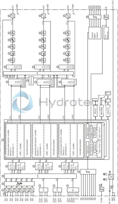
[ ] = Assignment to the block diagram
|
01 |
02 |
03 |
04 |
05 |
06 |
07 |
||||||
|
VT-HACD |
– |
3 |
– |
2X |
/ |
0 |
/ |
I |
– |
00 |
– |
000 |
|
01 |
Digital control electronics |
VT-HACD |
|
02 |
Standard |
3 |
|
03 |
Component series 20 ... 29 (20 ... 29: unchanged technical data and pin assignment) |
2X |
|
04 |
Bus system |
|
|
without bus |
0 |
|
|
PROFIBUS DP |
P |
|
|
Ethernet-based: |
||
|
PROFINET RT |
N |
|
|
EtherNet/IP |
E |
|
|
Position transducer |
||
|
05 |
Incremental/SSI |
I |
|
06 |
Hardware marking |
00 |
|
07 |
Options |
000 |
For applications outside these parameters, please consult us!
Block diagram: Structural editor
|
1 |
Analog voltage or current inputs |
|
1a |
High-impedance input AI1 |
|
2 |
SSI or incremental |
|
3 |
Enable input and digital inputs |
|
4 |
Analog input adjustment |
|
5 |
Switching matrix |
|
6 |
Math. connection of inputs |
|
7 |
32 blocks for command value generation, controller parameter switching |
|
8 |
Math. connection and/or controller |
|
9 |
Substitutional control |
|
10 |
Direction-dependent amplification |
|
11 |
Characteristic curve adjustment |
|
12 |
Residual velocity and overlap jump |
|
13 |
Offset |
|
14 |
Limitation |
|
15 |
Analog voltage or current outputs |
|
16 |
OK output and digital outputs |
|
17 |
Math. connection of outputs |
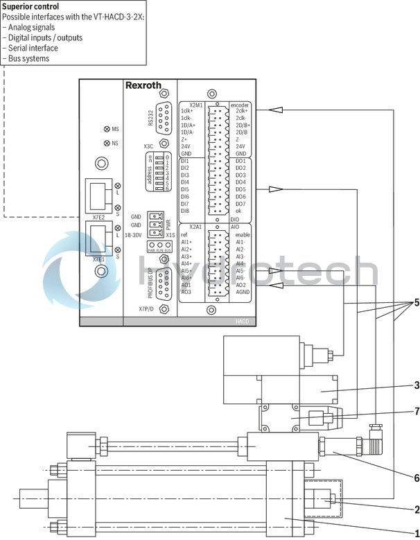
Example: VT-HACD-3-2X/… with one hydraulic cylinder axis
|
1 |
Differential cylinder |
|
2 |
integrated position measurement system |
|
3 |
Proportional servo valve with integrated control electronics |
|
4 |
VT-HACD-3-2X |
|
5 |
Connection cable |
|
6 |
Pressure transducer |
|
7 |
Sandwich plate shut-off valve (with connector switching amplifier) |
Pin assignment
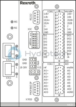
Pinout
|
X3C |
RS232 |
|
Pin |
|
|
1 |
LCAN_H |
|
2 |
TxD |
|
3 |
RxD |
|
4 |
reserved |
|
5 |
GND |
|
6 |
reserved |
|
7 |
reserved |
|
8 |
reserved |
|
9 |
LCAN_L |
|
X1S |
Power |
|
Pin |
|
|
1 |
GND |
|
2 |
GND |
|
3 |
18 – 30 V |
|
X7P |
PROFIBUS DP |
|
Pin |
|
|
1 |
reserved |
|
2 |
reserved |
|
3 |
RxD/TxD-P |
|
4 |
CNTR-P |
|
5 |
DGND |
|
6 |
VP |
|
7 |
reserved |
|
8 |
RxD/TxD-N |
|
9 |
reserved |
|
X7E1, X7E2 |
|
|
Ethernet ports |
|
|
X2M1 |
Encoder/DIO (Digital) |
|
1clk+ |
2clk+ |
|
1clk- |
2clk- |
|
1D/A+ |
2D/B+ |
|
1D/A- |
2D/B- |
|
Z+ |
Z- |
|
24V |
24V |
|
GND |
GND |
|
DI1 |
DO1 |
|
DI2 |
DO2 |
|
DI3 |
DO3 |
|
DI4 |
DO4 |
|
DI5 |
DO5 |
|
DI6 |
DO6 |
|
DI7 |
DO7 |
|
DI8 |
ok |
|
X2A1 |
AIO (Analog) |
|
ref |
enable |
|
AI1+ |
AI1- |
|
AI2+ |
AI2- |
|
AI3+ |
AI3- |
|
AI4+ |
AI4- |
|
AI5+ |
AI5- |
|
AI6+ |
AI6- |
|
AO1 |
AO2 |
|
AO3 |
AGND |
Notes:
The pins marked with "reserved" are reserved and must not be connected!
PROFIBUS DP (port X7P/D) is not available with the Ethernet version.
Machine tools
Plastics processing machines Special machinery Presses Transfer systemsTechnology functions
Sequence parameterization Positioning Pressure control Force control TablesHydraulic axes
Measurement system: incremental or absolute (SSI, gray, binary) analog 0 to ±10 V and 0(4) to 20 mA Actuating variable output voltage or current Freely configurable controller variants Position/pressure/force/velocity controller substitutional closed-loop control (position/pressure)Programming
User programming with PCOperation
Comfortable management of the machine and measured data on the PCProcess connection
Digital inputs and outputs, Analog inputs and outputs, PROFIBUS DP for the communication with a superior control system EtherNet/IP PROFINET RTAssembly
Top hat rail [si]35 mm[/si]1.38 in[imp]CE conformity
EMC Directive 2004/108/EC Applied harmonized standards: EN 61000-6-2:2005 EN 61000-6-3:2007Further information
https://www.boschrexroth.com/hacd
VT-HACD-3-2X/ (without Ethernet)
Dimensions in mm
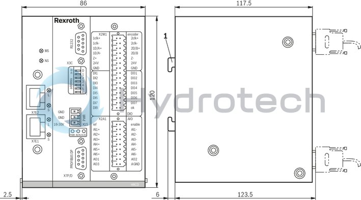
|
1 |
Installation on top hat rail TH 35-7.5 or TH 35-15 according to EN 60715 |
VT-HACD-3-2X/ (with Ethernet)
Dimensions in mm
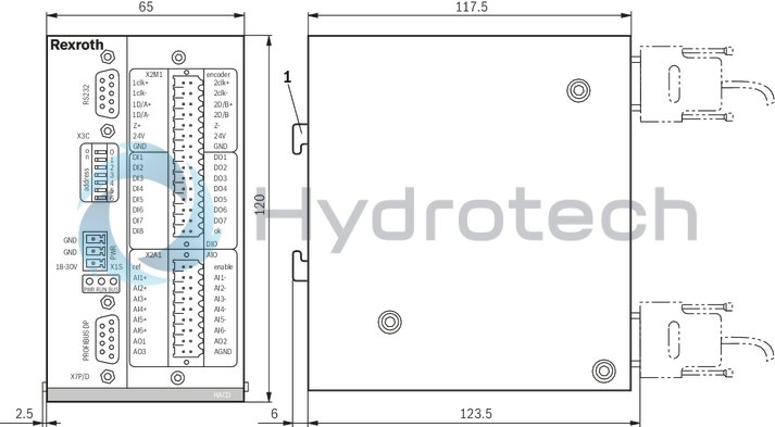
|
1 |
Installation on top hat rail TH 35-7.5 or TH 35-15 according to EN 60715 |
Software project planning
Project planning
The creation of a parameter file forms the basis for the function of the HACD. The parameter file contains the block structure of the HACD in which the links of the variables will be created. The parameter files are created in BODAC. The parameter file can be created offline and transferred to the HACD by means of a PC.
Proceed as follows for this software project planning:
1. Selection of the HACD.
2. Application is defined by means of the block structure.
3. Setting of the parameter values (sensor technology, controllers...).
4. The data is sent to the HACD.
5. Storage of the data in the flash.
6. The setting and the machine sequence are optimized at the machine.
PC program BODAC
To implement the project planning tasks, the BODAC PC program is available to the user. It can be used for the programming, setting and diagnosis of the HACD.
Scope of services:
Convenient dialog functions for the online or offline setting of the machine data Dialog window for the online setting of the parameter values Comprehensive options for displaying process variables, digital inputs, outputs, and flags Recording and graphical representation of up to eight process variables with great selection of trigger optionsPC system requirements:
Windows XP, Windows Vista, Windows 7, Windows 10 RAM (recommendation: 256 MB) 250 MB of available hard disk capacityNotice:
The BODAC PC program is not included in the scope of delivery.
It is available for free download!
Download on the Internet: www.boschrexroth.com/hacd
Enquiries: support.hacd@boschrexroth.de
Project planning / maintenance instructions / additional information
Product documentation for VT-HACD-3-2X
Data sheet 30543 Operating instructions 30543-B Environmental compatibility statement 30543-U BODAC software description 30543-01-B Commissioning instructions PROFIBUS interface 30543-01-Z Commissioning instructions EtherNET/IP interface 30543-04-Z Commissioning instructions PROFINET RT interface 30543-05-Z General information on the maintenance and commissioning of hydraulic components 07800/07900
Commissioning software and documentation on the Internet: www.boschrexroth.com/HACD
Maintenance instructions:
The devices have been tested in the plant and are supplied with default settings. Only complete devices can be repaired. Repaired devices are returned with default settings. User-specific settings are not accepted. The machine end-user must transfer all appropriate user parameters and programs again.