
BOSCH REXROTH
LC2A025A40D-1X/Z2F
R901336205
Directional Seat/Poppet Valves
Logic valves: LC2A 025.-1x/
BOSCH REXROTH
MATERIAL: R901336205
SUMMARY: Logic valves: LC2A 025.-1x/
Quantity in stock: 0
General
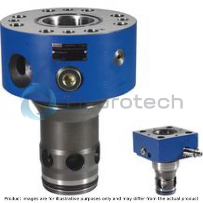
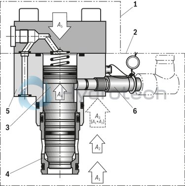
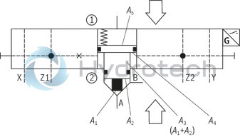
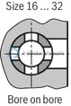
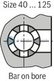
The 2-way cartridge valves type LC2A (hereinafter referredto as "active logics" (2) are designed in compact modular design and basically consist of cartridge (control spool (3) and socket (4), intermediate cover (5) as fixed functional unit and a control cover type LFA (1) that is part of the Rexroth standard logics program. This control cover (separate order, see data sheet 21010 or 21050) establishes the connection with the pilot control valves and/or other hydraulic elements and thus integrates the most different functions - irrespective of the basic assembly. Virtually all standard and special control covers type LFA can be mounted. Optionally, the active logics (2) is available with position switch (6). By default, the "closed" position of the control spool (3) is recorded. The receiving hole for the position switch is provided as a standard. This means that the position switch "Q7" can be retrofitted at any time without requiring adjustments. In contrast to the logic assemblies with only one control area in the spring chamber ("passive logics"), the name "active logics" significantly stands for a version with differential spool, with at least one additional control area A4 ("two-level active logics"). This area allows for the opening and keeping open of the active logics (2) by means of pilot pressure (without the necessity of pressure in the main ports A or B). The spring chamber area A5 of the control spool (3) consists of the individual areas A1 + A2 + A4. Compared to passive logics without control area A4, this results in excess area which, with suitable hydraulic circuitry, offers advantages during closing and keeping closed (excessive force, closing velocity).
In general
Area total A5 = A1 + A2 +A4 = A3 + A4 The areas A1, A2 and A4 are effective in the opening direction, area A5 (and the spring force) in closing direction. So the resulting effective force determines the position and movement of the control spool (3). Usually, there are no interim positions in the directional function variants. The direction of flow is free and can thus be perfectly adjusted to the application. Active logics type LC2A are generally equipped with spool sealing and are therefore leakage-free inside. The seat area is hydraulically "tight".
Active logics for directional function
Depending on the task, different control spool versions are possible. The active area can be connected with the available pilot oil guides in almost any way and in this way, most different functions can be realized with only 1 basic assembly.
Installation bore
The active logics type LC2A can be directly installed in a standard installation bore according to ISO 7368 (see dimensions). Thus, it is also suitable as retrofitting for existing "passive logics" that must be leakage-free inside or require position monitoring or faster closing times.
Type LC2A 025 ...-1X/.Q7G24…
(with control cover type LFA . D... and monitoring of the closed position of the valve poppet)
|
01 |
02 |
03 |
04 |
05 |
06 |
07 |
08 |
09 |
10 |
11 |
12 |
13 |
14 |
15 |
16 |
17 |
18 |
19 |
20 |
21 |
22 |
23 |
24 |
||
|
LC |
2A |
– |
1X |
/ |
* |
|
01 |
Logic Cartridge |
LC |
|
02 |
2-level, active |
2A |
|
03 |
Size 16 |
016 |
|
Size 25 |
025 |
|
|
Size 32 |
032 |
|
|
Size 40 |
040 |
|
|
Size 50 |
050 |
|
|
Size 63 |
063 |
|
|
Size 80 |
080 |
|
|
Size 100 |
100 |
|
|
Size 125 (only version "F", valve poppet with overlap; not with version "450") |
125 |
|
|
Control spool design (area ratio see product description) |
||
|
04 |
A1:A2 = 2:1(A2 = 50 %) |
A |
|
A1:A2 = 14,3 : 1 (A2 = 7 %) |
B |
|
|
A1:A2 = 1 : 0 (A2 = 0 %) |
D |
|
|
05 |
Without spring |
00 |
|
With spring, cracking pressure approx. 4 bar (referring to control spool design "A") |
40 |
|
|
06 |
Valve poppet without damping nose |
E |
|
Valve poppet with damping nose |
D |
|
|
Valve poppet with overlap (preferred with "spool position monitoring"; only with control spool design "B") |
F |
|
|
07 |
Component series 10 ... 19 (10 ... 19: unchanged installation and connection dimensions) |
1X |
|
Maximum operating pressure |
||
|
08 |
420 bar (standard) |
no code |
|
450 bar |
450 |
|
|
Active area1) connected to port: |
||
|
09 |
Z1 |
Z1 |
|
Z2 |
Z2 |
|
|
Z1 and Z2 |
U |
|
|
X (not with version "450") |
X |
|
|
Y (not with version "450") |
Y |
|
|
Spool position monitoring 2) (position switch 1 = "1"; position switch 2 = "2") (version "450" only with "Q7", "Q9" and "without") |
||
|
10 |
Position monitoring "closed" |
|
|
Without position switch ("1" on side "Y" – can be retrofitted) |
no code |
|
|
With 1 position switch ("1" on side "Y" – mounted) |
Q7 |
|
|
With 2 position switches ("1" - mounted on side "Y", attachment side of "2" NG-dependent ‒ mounted) |
Q7Q7 |
|
|
With 1 position switch and second installation bore ("1" on side "Y" – not fitted, attachment side of "2" NG-dependent– mounted) |
Q.Q7 |
|
|
Without position switch, with 2 installation bores ("1" on side "Y" – not fitted, attachment side of "2" NG dependent– not fitted) |
Q.Q. |
|
|
Combined position monitoring "1" (closed) and "2" (open) 3) |
||
|
With 2 position switches "1" on side "Y" – mounted, attachment side of "2" NG-dependent – mounted) |
Q7Q7T |
|
|
Without position switch, with 2 installation bores ("1" on side "Y" – not fitted, attachment side of "2" NG dependent– not fitted) |
Q.Q.T |
|
|
With 1 position switch and second installation bore ("1" on side "Y" – not fitted, attachment side of "2" NG-dependent– mounted) |
Q.Q7T |
|
|
- Position monitoring "closed"; NAMUR 4) |
||
|
With 1 position switch ("1" on side "Y" – mounted) |
Q8 |
|
|
– Analog, position sensing |
||
|
Inductive sensor with analog output (1 … 9 V DC); only with versions "LC2A . D40E-1X/…A", "LC2A . A.D-1X/…" and "LC2A . B.F-1X/…" |
Q9 |
|
|
Combination "analog" and "digital" upon request |
||
|
Electrical connection for position switch 5) |
||
|
11 |
Without position switch |
no code |
|
UB = 24 V DC (standard; only with version "Q7" and "Q9") |
G24 |
|
|
UB = 8 V DC (NAMUR; only with version "Q8"; not with version "450") |
G08 |
|
|
Pilot oil bore in the control spool 6) |
||
|
12 |
Without pilot oil bore |
no code |
|
- Pilot oil bore A → spring chamber (NG25 to 100 only) |
||
|
NG25 – Maximum pilot oil bore Ø 10.0 mm |
A100 |
|
|
NG32 – Maximum pilot oil bore Ø 13.0 mm |
A130 |
|
|
NG40 – Maximum pilot oil bore Ø 16.0 mm |
A160 |
|
|
NG50 – Maximum pilot oil bore Ø 20.0 mm |
A200 |
|
|
NG63 – Maximum pilot oil bore Ø 26.0 mm |
A260 |
|
|
NG80 – Maximum pilot oil bore Ø 32.0 mm |
A320 |
|
|
NG100 – Maximum pilot oil bore Ø 40.0 mm |
A400 |
|
|
Nozzle fitting |
||
|
13 |
Without orifice |
no code |
|
With orifice in channel X – ➀ |
X** |
|
|
14 |
Without orifice |
no code |
|
With orifice in channel F – to the active area |
F** |
|
|
15 |
Without orifice |
no code |
|
With orifice in channel Z1 – ➁ (not with version "X" and "Y") |
D** |
|
|
16 |
Without orifice |
no code |
|
With orifice in channel Z1 – ➀ |
Z** |
|
|
17 |
Without orifice |
no code |
|
With orifice in channel Y – ➀ |
Y** |
|
|
18 |
Without orifice |
no code |
|
With orifice in channel Z1 – ➁ (not with version "X" and "Y") |
S** |
|
|
19 |
Without orifice |
no code |
|
With orifice in channel Z2 – ➀ |
W** |
|
|
20 |
Without orifice |
no code |
|
With orifice in channel X – ➁ (not with version "Z1", "Z2" and "U") |
H** |
|
|
21 |
Without orifice |
no code |
|
With orifice in channel Y – ➁ (not with version "Z1", "Z2" and "U") |
L** |
|
|
Corrosion resistance |
||
|
22 |
None |
no code |
|
Improved corrosion protection (240 h salt spray test according to EN ISO 9227) |
J3 |
|
|
Seal material 7) |
||
|
23 |
FKM seals (preferred) |
F |
|
NBR seals (see technical data) |
N |
|
|
H-ECOPUR seals (with version "450") |
P |
|
|
24 |
Further details in the plain text |
* |
| 1) | For structural-inherent reasons, the active surface (A4) can only be combined with one of the two pilot oil pairs "Z1/Z2" or "X/Y". Any subsequent change from "Z1/Z2" to "X/Y" is only possible with NG125. |
| 2) | BG certificate, see electrical connection |
| 3) | Not for NG16, 25 and 32 |
| 4) | Only with version "G08". Evaluation electronics designed and approved of for NAMUR interfaces are standard. |
| 5) | Mating connectors, separate order, see "Accessories" |
| 6) | Only with type LC2A . D40E-1X/… for "check valve function"; the maximum pilot oil bore Ø has been determined according to thesize. |
| 7) | The selection of the seal material depends on the operating parameters (fluid, temperature, etc.) |
➀ = component side
➁ = plate side
Order example orifice fitting:
** = dimension in mm x 10 – e.g. orifice Ø1.2 mm in channel X – ① = "X12" “99” = blanking plug e.g. blanking plug in channel Z2 – ① = “W99”general
|
Size |
16 | 25 | 32 | 40 | 50 | 63 | 80 | 100 | 125 | |
|
Ambient temperature range |
°C |
-20 … +80 | ||||||||
|
MTTFD values according to EN ISO 13849 1) |
Years |
150 | ||||||||
| 1) | For further details, see data sheet 08012 |
hydraulic
|
Size |
16 | 25 | 32 | 40 | 50 | 63 | 80 | 100 | 125 | |
|
Maximum operating pressure |
bar |
450 | ||||||||
|
Maximum flow 1) |
l/min |
17000 | ||||||||
|
Hydraulic fluid |
see table | |||||||||
|
Hydraulic fluid temperature range |
°C |
-20 … +80 | ||||||||
|
Viscosity range |
mm²/s |
2.8 … 500 | ||||||||
|
Maximum admissible degree of contamination of the hydraulic fluid 2) |
Class 20/18/15 according to ISO 4406 (c) | |||||||||
| 1) | Measured with p = 10 bar; if functionally higher Δp values are admissible, higher flows are possible, as well. |
| 2) | The cleanliness classes specified for the components must be adhered to in hydraulic systems. Effective filtration prevents faults and simultaneously increases the life cycle of the components. For the selection of the filters, see www.boschrexroth.com/filter. |
|
Hydraulic fluid |
Classification |
Suitable sealing materials |
Standards |
Data sheet |
|
|
Mineral oils |
HL, HLP |
NBR, FKM, H-ECOPUR |
DIN 51524 |
90220 |
|
|
Bio-degradable 1) |
Insoluble in water |
HETG |
FKM, H-ECOPUR |
ISO 15380 |
90221 |
|
HEES |
FKM, H-ECOPUR |
||||
|
Soluble in water |
HEPG |
FKM |
ISO 15380 |
||
|
Flame-resistant |
Water-free |
HFDU (glycol base) |
FKM, H-ECOPUR |
ISO 12922 |
90222 |
|
HFDU (ester base) |
FKM, H-ECOPUR |
||||
|
HFDR |
FKM |
||||
|
Containing water 1) |
HFC (Fuchs Hydrotherm 46M, Petrofer Ultra Safe 620) |
NBR |
ISO 12922 |
90223 |
|
|
Important information on hydraulic fluids: For further information and data on the use of other hydraulic fluids please contact us. There may be limitations regarding the technical valve data (temperature, pressure range, life cycle, maintenance intervals, etc.).Flame-resistant – containing water: Life cycle as compared to operation with mineral oil HL, HLP 30 … 100% Maximum hydraulic fluid temperature 60 °CBio-degradable and flame-resistant: If this hydraulic fluid is used, small amounts of dissolved zinc may get into the hydraulic system. |
|||||
| 1) | Not recommended for corrosion-protected version "J3" and "J5" (contains zinc) |
|
Size of the annulus area |
||||||||||
|
Surface in cm2 |
Type |
Size |
||||||||
|
16 |
25 |
32 |
40 |
50 |
63 |
80 |
100 |
125 |
||
|
A1 |
LC2A . A... |
1,89 |
4,26 |
6,79 |
11,1 |
19,63 |
30,02 |
37,9 |
63,6 |
– |
|
LC2A . B... |
2,66 |
5,73 |
9,51 |
15,55 |
26,42 |
41,28 |
52,8 |
89,1 |
133,7 |
|
|
LC2A . D... |
2,84 |
6,16 |
10,18 |
16,62 |
28,27 |
44,2 |
56,74 |
95,0 |
– |
|
|
A2 |
LC2A . A... |
0,95 |
1,89 |
3,39 |
5,52 |
8,64 |
14,0 |
18,84 |
31,4 |
– |
|
LC2A . B... |
0,18 |
0,43 |
0,67 |
1,07 |
1,85 |
2,90 |
3,94 |
5,9 |
9,3 |
|
|
LC2A . D... |
– |
– |
– |
– |
– |
– |
– |
– |
– |
|
|
A3 |
LC2A . A/B/D... |
2,84 |
6,16 |
10,18 |
16,62 |
28,27 |
44,2 |
56,74 |
95 |
143 |
|
A4 |
0,62 |
1,39 |
2,39 |
3,81 |
5,94 |
8,75 |
11,2 |
19,1 |
22,0 |
|
|
A5 |
3,46 |
7,55 |
12,6 |
20,4 |
34,2 |
52,8 |
67,9 |
114,0 |
165 |
|
|
Area ratio A5 : A4 2) |
5,58 |
5,43 |
5,27 |
5,35 |
5,76 |
6,03 |
6,06 |
5,97 |
7,5 |
|
| 2) When determining the nozzle diameters for influencing the switching time, please observe the area ratio A5 : A4 (inflowing and outflowing hydraulic fluid in the control chambers A5 and A4) | |
| In case of non-compliance, pressure conversion can be applied! |
|
Control spool form |
|||||||||||
|
Type |
Size |
||||||||||
|
16 |
25 |
32 |
40 |
50 |
63 |
80 |
100 |
125 |
|||
|
Stroke |
cm |
LC2A . ..E... |
0,9 |
1,17 |
1,4 |
1,7 |
2,1 |
2,3 |
2,4 |
3,0 |
‒ |
|
LC2A . ..D... |
0,9 |
1,17 |
1,4 |
1,9 |
2,3 |
2,8 |
3,0 |
3,8 |
4,8 |
||
|
LC2A . ..F... |
0,9 |
1,17 |
1,4 |
1,9 |
2,3 |
2,8 |
3,0 |
3,8 |
4,8 |
||
|
Pilot volume |
cm3 |
LC2A . ..E... |
3,1 |
8,8 |
17,6 |
34,7 |
71,8 |
121,4 |
163,0 |
339,0 |
‒ |
|
LC2A . ..D... |
3,1 |
8,8 |
17,6 |
34,8 |
78,7 |
147,8 |
203,7 |
429,4 |
792 |
||
|
LC2A . ..F... |
3,1 |
8,8 |
17,6 |
34,8 |
78,7 |
147,8 |
203,7 |
429,4 |
792 |
||
|
Theoretical pilot flow 3) |
l/min |
LC2A . ..E... |
3,7 |
10,6 |
21,1 |
41,6 |
86,6 |
145,7 |
195,6 |
406,8 |
‒ |
|
LC2A . ..D... |
3,7 |
10,6 |
21,1 |
46,6 |
94,4 |
177,4 |
244,4 |
515,3 |
950,4 |
||
|
LC2A . ..F... |
3,7 |
10,6 |
21,1 |
46,6 |
94,4 |
177,4 |
244,4 |
515,3 |
950,4 |
||
|
Weight |
kg |
LC2A ... |
2,2 |
2,6 |
3,9 |
10,3 |
16,5 |
30,5 |
52,5 |
92,0 |
167 |
|
Cracking pressure in bar |
||||||||||
|
Type |
Size |
|||||||||
|
16 |
25 |
32 |
40 |
50 |
63 |
80 |
100 |
125 |
||
|
Direction of flow A to B 4) |
LC2A . A... |
3,50 |
3,90 |
3,80 |
4,0 |
4,11 |
3,8 |
3,13 |
3,04 |
‒ |
|
LC2A . B... |
2,48 |
2,90 |
2,70 |
2,86 |
3,05 |
2,8 |
2,25 |
2,17 |
1,45 |
|
|
Direction of flow B to A 4) |
LC2A . A... |
6,96 |
8,74 |
7,6 |
8,05 |
9,34 |
8,15 |
6,3 |
6,2 |
‒ |
|
LC2A . B... |
36,6 |
38,3 |
38,6 |
41,5 |
43,6 |
39,4 |
30,2 |
32,5 |
20,7 |
|
|
Control open with active area |
Version "40" |
>30 |
||||||||
|
Without spring |
>12 |
|||||||||
| 3) Quantity indications refer to a theoretical switching time of t = 50 ms (control chamber A5) | |
| 4) With direction of flow B → A, the control spool version "D" (“0 %") has no directly effective control open area (A2 = 0). For this direction of flow, the active area is to be controlled. A minimum pressure of 30 bar is recommended. The cracking pressure of the control spool version "D" almost corresponds to version "B" (A → B) |
For applications outside these parameters, please consult us!
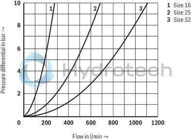
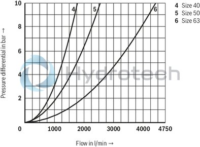
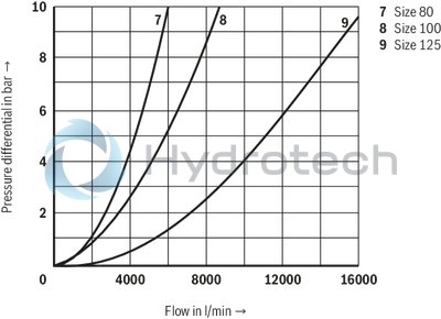
(simulated with HLP46, ϑÖl = 40±5 °C)
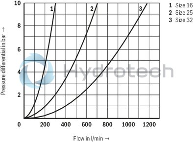
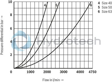
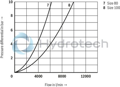
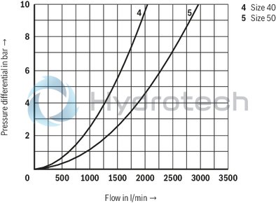
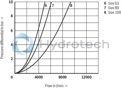
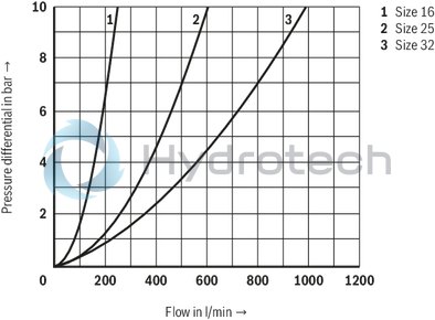
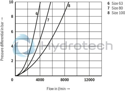
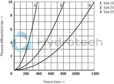
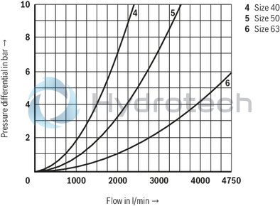
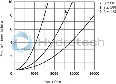
without damping nose "E", direction of flow A → B
without damping nose "E", direction of flow A → B
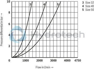
without damping nose "E", direction of flow A → B
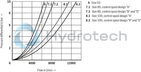
Notice:
The specified characteristic curves were simulated with 100% spool stroke and an aligned socket (see sketch under recommended socket alignment). The simulation results were validated by measurement results. The basis was an installation geometry with ØD3* (see installation under dimensions) and a simulation model according to ISO 4411/2008-10-01.
Recommended socket alignment:
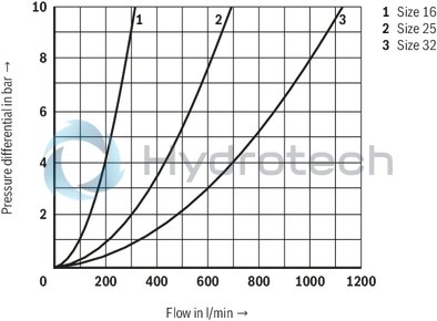
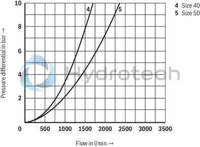
without damping nose "E", direction of flow B → A
without damping nose "E", direction of flow B → A
without damping nose "E", direction of flow B → A
Notice:
The specified characteristic curves were simulated with 100% spool stroke and an aligned socket (see sketch under recommended socket alignment). The simulation results were validated by measurement results. The basis was an installation geometry with ØD3* (see installation under dimensions) and a simulation model according to ISO 4411/2008-10-01.
with damping nose “D”, direction of flow A → B
with damping nose “D”, direction of flow A → B
with damping nose “D”, direction of flow A → B
Notice:
The specified characteristic curves were simulated with 100% spool stroke and an aligned socket (see sketch under recommended socket alignment). The simulation results were validated by measurement results. The basis was an installation geometry with ØD3* (see installation under dimensions) and a simulation model according to ISO 4411/2008-10-01.
with damping nose "D", direction of flow B → A
with damping nose "D", direction of flow B → A
with damping nose "D", direction of flow B → A
Notice:
The specified characteristic curves were simulated with 100% spool stroke and an aligned socket (see sketch under recommended socket alignment). The simulation results were validated by measurement results. The basis was an installation geometry with ØD3* (see installation under dimensions) and a simulation model according to ISO 4411/2008-10-01.
with overlap “F”, direction of flow A → B
with overlap “F”, direction of flow A → B
with overlap “F”, direction of flow A → B
Notice:
The specified characteristic curves were simulated with 100% spool stroke and an aligned socket (see sketch under recommended socket alignment). The simulation results were validated by measurement results. The basis was an installation geometry with ØD3* (see installation under dimensions) and a simulation model according to ISO 4411/2008-10-01.
with overlap "F", direction of flow B → A
with overlap "F", direction of flow B → A
with overlap "F", direction of flow B → A
Notice:
The specified characteristic curves were simulated with 100% spool stroke and an aligned socket (see sketch under recommended socket alignment). The simulation results were validated by measurement results. The basis was an installation geometry with ØD3* (see installation under dimensions) and a simulation model according to ISO 4411/2008-10-01.
Inductive sensor with analog output type Q9
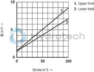
Notice:
The maximum sensor voltage US with 100% stroke is size- and/or tolerance-dependent and may range between 7 and 9 V DC. The inductive sensor is adjusted so that with 0% stroke, an output voltage of 1 V DC is available.
for orifice selection
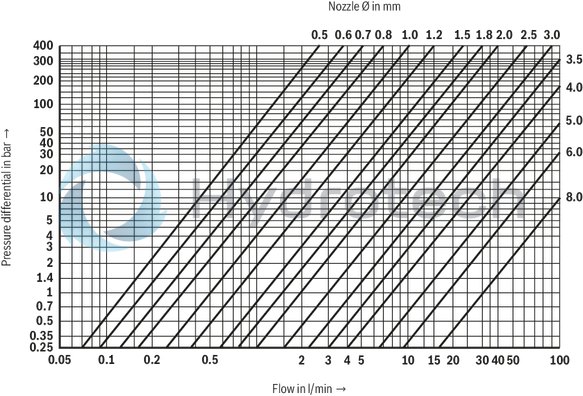
Orifices
|
Orifice Ø in mm |
Order numbers |
Material numbers |
||||||
|
M6 conical |
M8 x 1 conical |
G 1/8 conical |
G 1/4 conical |
G 3/8 conical |
G 1/2 conical |
G 1 conical |
||
|
– |
00 |
– |
– |
– |
– |
– |
– |
– |
|
0,5 |
05 |
R913040356 |
R913017600 |
R913030187 |
R913040456 |
– |
– |
– |
|
0,6 |
06 |
R913040358 |
R913017605 |
R913017606 |
R913020197 |
– |
– |
– |
|
0,7 |
07 |
R913040360 |
R913017609 |
R913046092 |
– |
– |
– |
– |
|
0,8 |
08 |
R913029447 |
R913017614 |
R913017616 |
R913017615 |
R913040481 |
R913040499 |
– |
|
1,0 |
10 |
R913019186 |
R913017621 |
R913024679 |
R913017622 |
R913040484 |
R913040500 |
– |
|
1,2 |
12 |
R913040362 |
R913017627 |
R913017629 |
R913017628 |
R913040486 |
R913040501 |
– |
|
1,5 |
15 |
R913028337 |
R913017637 |
R913017639 |
R913017638 |
R913040488 |
R913028317 |
– |
|
1,8 |
18 |
R913030186 |
R913017644 |
R913017646 |
R913017645 |
R913040489 |
R913045913 |
– |
|
2,0 |
20 |
R913029870 |
R913017651 |
R913040450 |
R913017652 |
R913028417 |
R913028336 |
– |
|
2,5 |
25 |
R913032543 |
R913035796 |
R913017656 |
R913019582 |
R913040493 |
R913040502 |
– |
|
3,0 |
30 |
R913040368 |
R913017661 |
R913017663 |
R913017662 |
R913018266 |
R913040503 |
R913040467 |
|
3,5 |
35 |
– |
R913017667 |
R913040452 |
R913040463 |
R913028318 |
R913019856 |
R913040469 |
|
4,0 |
40 |
– |
R913017670 |
R913027078 |
R913040464 |
R913018265 |
R913029168 |
R913040470 |
|
4,5 |
45 |
– |
R913046571 |
R913017671 |
R913040465 |
– |
R913040506 |
– |
|
5,0 |
50 |
– |
– |
R913017673 |
R913040468 |
R913023871 |
R913019857 |
R913040471 |
|
5,5 |
55 |
– |
– |
R913027077 |
– |
R913040495 |
R913053659 |
– |
|
6,0 |
60 |
– |
– |
– |
– |
R913023870 |
R913028418 |
R913020247 |
|
7,0 |
70 |
– |
– |
– |
R913040461 |
R913017675 |
R913040509 |
– |
|
7,5 |
75 |
– |
– |
– |
– |
R913023430 |
– |
R913018328 |
|
8,0 |
80 |
– |
– |
– |
– |
R913046570 |
R913040510 |
R913020246 |
|
closed |
99 |
R913019128 |
R913019129 |
R913019137 |
R913019136 |
R913019138 |
– |
R913019140 |
|
Plug screws |
||
|
Thread |
Tightening torque MA in Nm ±10 % |
|
|
420 bar |
450 bar |
|
|
G 1/8 |
12 |
18 |
|
G 1/4 |
30 |
45 |
|
G 3/8 |
55 |
83 |
|
G 1/2 |
80 |
120 |
|
G 3/4 |
135 |
175 |
|
G 1 |
225 |
270 |
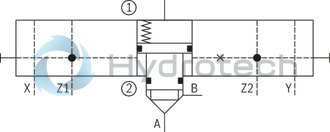
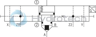
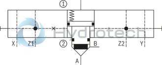
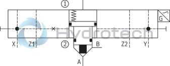
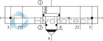
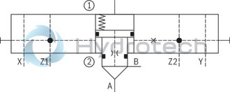
Examples of control spool forms and circuitries of the active area
➀ = component side
➁ = plate side
Type LC2A . B40E-1X/Z1...
Type LC2A . A40D-1X/Z1Q7G24…
Type LC2A . B40D-1X/Z2…
Type LC2A . A40D-1X/YQ7G24…
Type LC2A . D40D-1X/X…
Type LC2A . D40E-1X/Z1..A…
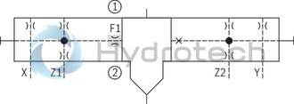
Assignment of the "active area" A4
Type LC2A …-1X/Z1…
(F1 not fitted)
Type LC2A …-1X/Z2 …
(F2 not fitted)
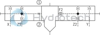
Type LC2A …-1X/U …
(F1 and F2 not fitted)
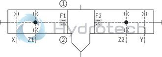
Type LC2A …-1X/Y …
(F2 not fitted)
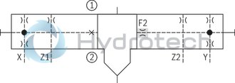
Type LC2A …-1X/X …
(F1 not fitted)
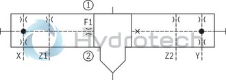
For details regarding the "open" or "closed" circuitry of channels F1 and F2 (control of the active area) refer to "Dimensions" and "Ordering code".
Depending on the "Active area" ordering code, the number of possible orifice fittings is different in the continuous pilot oil guides, see "Orifice assignments" below.
Orifice assignment
Orifice fitting of the pilot oil guides in the cover
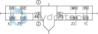
The fitting and assignment of the "active area" is not shown here (see "Assignment of the active area")
For details on the dimensions of the orifice installation bores "X" to "L", see "Dimensions".
On the component side, the orifice installation bores are always completely available; on the plate side, only the combinations of versions "H" and "L" or "D" and "S" are possible, see "Ordering code".
Notice:
With control channels that are not required, you must either use a blanking plug ".99" or the corresponding cover.
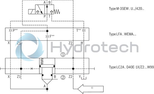
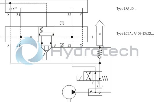
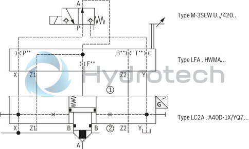
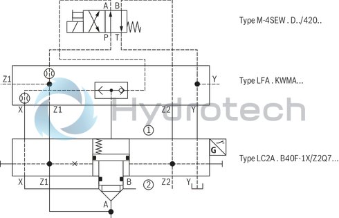
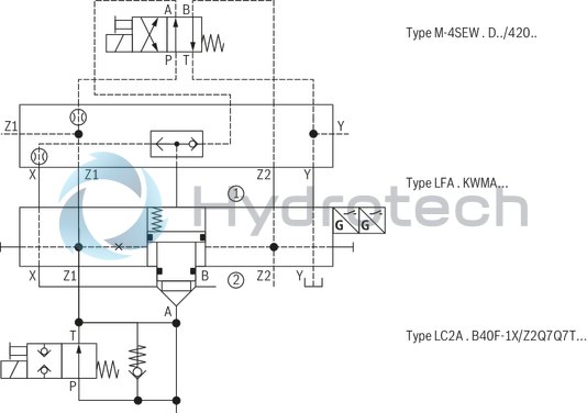
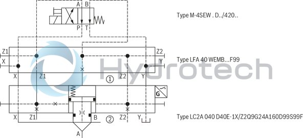
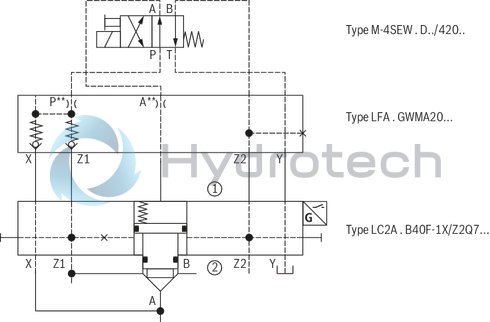
Circuit examples (schematic diagram, function must be checked with the application)
Notice:
It has to be ensured that pilot oil ports that are not required (blanking plugs) and all pressurized transitions between LFA and LC2A (R-rings) are sealed. This is particularly true for variants marked with *.
Check valve, releasable
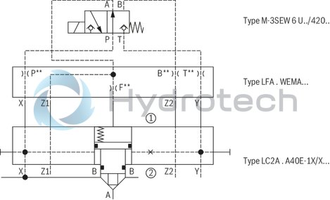
Function "closing pressure-supported by excess area" (e.g. with control cover type "D")
"Passive logics with piston seal and spool position monitoring" function (Closing with spring force without excess area; here with control cover type "D")
ideal for retrofitting of existing circuits
"Self-closing" or "open basic position" (e.g. with control cover type "WEMA")
| 1) | Pilot pressure |
Control spool remains open as long as FZ2 ≥ FA + 30 bar
In case of failure or drop of the pilot pressure, the logic element closes hydraulically. Irrespective thereof, the logic element can be opened by unloading the spring chamber (minimum pilot pressure required).
"Pulling" and "Safe keeping closed" function
| 1) | Consumer |
The control spool of the active logics can be opened or closed depending on the two pilot oil pressures X and Z2. Thus, free flow is possible in both directions, irrespective of the pressure level in port B.
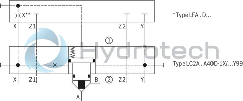
"Passive logics with piston seal" function, spool position monitoring and stroke limitation
Advantages:
Retrofitting for existing installation using the existing control cover type LFA and pilot control valves Leakage-free locking Position monitoring Shortened closing time"Closed basic position" function; safe locking, increased closing force
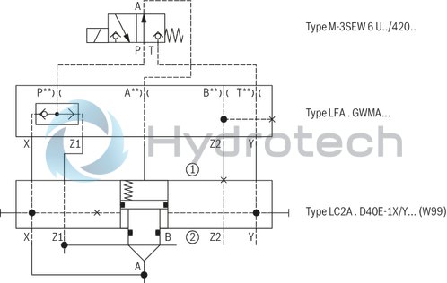
Advantages:
"Safe locking" in both directions Control spool cannot be controlled open from side B (version "...D.E...") Position switch retrofittable Shortened switching timeAdvantages:
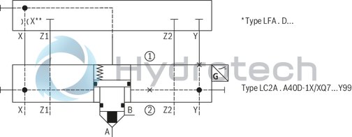
Leakage-free separation of the two pilot pressures “X” and “Z1” Function of a hydraulic detent (“Keeping open”, also in case of pilot pressure failure) Permits complete pressure compensation of both main ports"Check valve" and "Safe locking" function; increased closing force
Advantages:
Leakage-free locking Increased closing force (shortened closing time)“Check valve” (releasable) and “Safe locking” function; “Keeping open” additional function
Advantages:
"Safe locking" in both directions Check valve function that can be switched off Leakage-free locking Monitoring of the open and closed position"Check valve circuit" function, self-locking, fast-closing
Advantages:
Maximum load pressure in channel A 500 bar (condition: maximum pressure in channel B 250 bar) Very fast closing by internal spring chamber filling (e.g. NG63 < 20 ms) High locking force Analog position sensing (optional)“Separation between both pilot pressures and hydraulic keeping open in case of pilot pressure failure” function
Inductive position switch type Q7
The electrical connection is realized via a 4-pole mating connector with connection thread M12 x 1 (separate order). The inductive position switch can be connected as normally closed or normally open contact.
Features:
Adjustment-free assembly due to fixed stop Certification according to CE and cULus|
Connection voltage |
V |
12 ... 30 | |
|
Admissible residual ripple |
% |
< 15 | |
|
Load capacity |
mA |
200 | |
|
Tightening torque MA |
Nm |
10 | |
| + 5 Nm | |||
|
Switching outputs 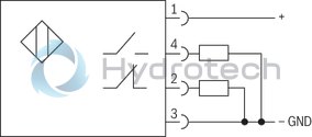 |
PNP transistor outputs, load between switching outputs and GND | ||
|
Pinout  |
1 |
+UB | |
|
2 |
Normally closed contact | ||
|
3 |
L0 | ||
|
4 |
Normally open contact | ||
Notes:
The "closed" spool position is adjusted to and optimized for a condition at operating temperature. Considerably deviating operating temperatures thus influence the absolute switching position as well as its hysteresis. The position switch type Q7 has no connection for protective earthing conductors! Assembly tool for position switch type Q7 or blind plug upon request. BG certificate (only size 16 … 100 and valve poppet version "D" and "F"): The respectively valid "MHHW 10014" certificate for using the active logics type LC2A with position switch type Q7 in hydraulic security locks in injection molding machines according to the manufacturer's installation instructions is available upon request.Inductive position switch type Q8
The electrical connection is realized via a 4-pole mating connector with connection thread M12 x 1 (separate order).
Features:
Certification according to CE Explosion protection according to Ex II 2G Ex ia IIC T6 Use not with version "450"|
Connection voltage (DC voltage) |
V |
8.2 | |
| +9 %/-6 % | |||
|
Maximum current consumption, dampened: |
mA |
1 | |
|
Maximum current consumption, not dampened: |
mA |
4 | |
|
Tightening torque MA |
Nm |
10 | |
|
Nm |
+ 5 | ||
|
Switching outputs  |
NAMUR evaluation electronics necessary | ||
|
Pinout |
1 |
Current source | |
|
2 |
- | ||
|
3 |
0 V, GND | ||
|
4 |
- | ||
Inductive sensor with analog output type Q9
The electrical connection is realized via a 4-pole mating connector with connection thread M12 x 1 (separate order).
Features:
Certification according to CE|
Connection voltage |
V |
15 ... 30 | |
|
Admissible residual ripple |
% |
< 15 | |
|
Tightening torque MA |
Nm |
10 | |
| + 5 Nm | |||
|
Analog output: 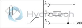 |
Load resistance ≥ 2 kΩUS = 1 ... 9 V DC (in the installed, adjusted condition)Notice:The maximum sensor voltage US with 100% stroke is size- and/or tolerance-dependent and may range between 7 and 9 V DC. The inductive sensor is adjusted so that with 0% stroke, an output voltage of 1 V DC is available. | ||
|
Pinout |
1 |
+UB | |
|
2 |
- | ||
|
3 |
L0 | ||
|
4 |
0 … 10 V DC | ||
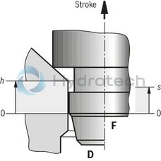
Switching point behavior and overlap: Valve poppet with damping nose "D" or overlap nose "F" and position overlap "closed"
|
h |
Overlap stroke (mechanical) |
|
s |
Switching point window (electrical) |
|
qv0 |
Maximum flow until hmin |
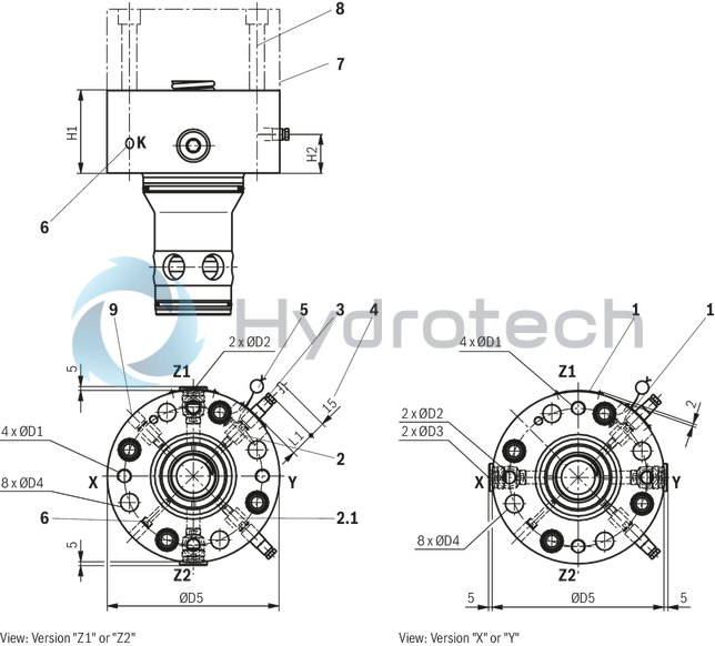
Characteristic curve position switch type Q7
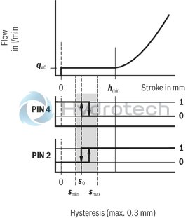
NG16 ... 63
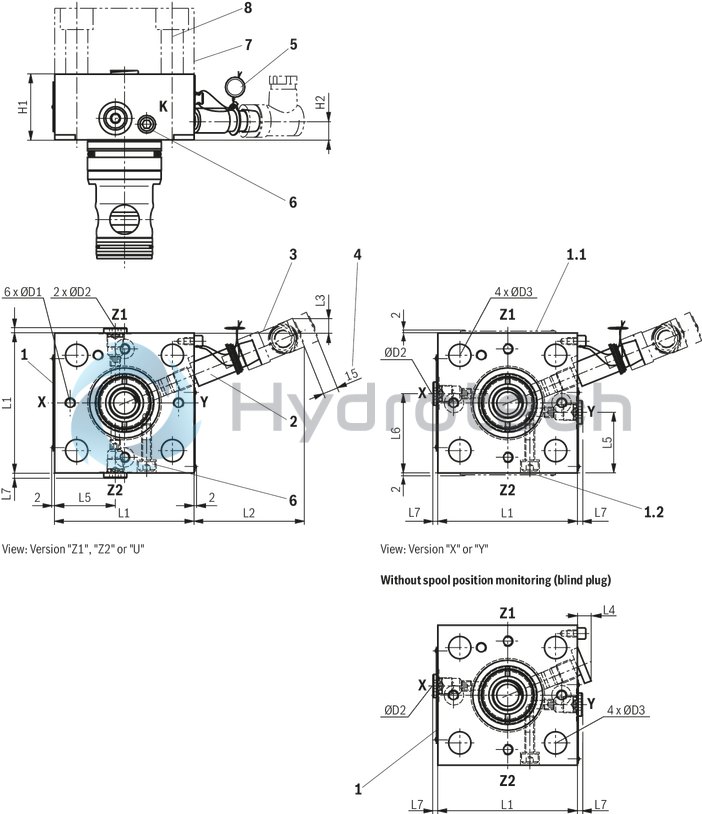
With spool position monitoring (1 position switch "Q7", position monitoring "closed")
(with version "450" only with pilot oil bore "Z1" and "Z2")
Dimensions in mm
|
1 |
Name plate |
|
1.1 |
Name plate NG16 and 25 |
|
2 |
Position switch (optional) or blind plug |
|
3 |
Mating connector (separate order) |
|
4 |
Space required to remove the mating connector |
|
5 |
Sealing by the factory |
|
6 |
Transport lock for control spool (marking K). Don't remove! Loosening or disassembly and assembly only admissible in case of service/repair! |
|
7 |
Standard end/control cover type LFA... (separate order, depends on the basic hydraulic function) |
|
8 |
Valve mounting screws (separate order, see table) |
|
NG |
L1 |
L2 |
L3 |
L4 |
L5 |
L6 |
L7 1) |
H1 |
H2 |
ØD1 |
ØD2 |
ØD3 |
|
|
mm |
mm |
mm |
mm |
mm |
mm |
mm |
mm |
mm |
mm |
mm |
|||
| 16 | 80 | 67 | 15 | 7 | 34.5 | 45.5 |
5 10 |
40 | 11.5 | M6 | G 1/8 | 8.5 | |
| 25 | 85 | 67 | 9.5 | 10 | 37 | 48 |
5 10 |
40 | 11.5 | M6 | G 1/8 | 13.5 | |
| 32 | 100 | 65 | 2 | 7 | 45 | 55 |
5 10 |
50 | 13.5 | M8 x 1 | G 1/8 | 19 | |
| 40 | 125 | 58 | - | - | 56 | 69 |
5 11 |
80 | 29.5 | G 1/8 | G1/4 | 22 | |
| 50 | 140 | 58 | - | - | 63.5 | 63.5 |
5 11 |
100 | 42.5 | G 1/8 | G1/4 | 24 | |
| 63 | 180 | 45 | - | - | 82.5 | 82.5 |
5 11 |
110 | 45.5 | G1/4 | G3/8 | 26 | + 1 |
| 1) | Version "450" |
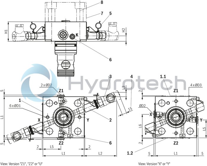
NG16 … 32
With spool position monitoring (2 position switches “Q7”, position monitoring “closed”)
(not with version "450")
Dimensions in mm
|
1.1 |
Name plate NG16 and 25 |
|
1.2 |
Name plate NG32 … 63 |
|
2 |
Position switch (optional) or blind plug |
|
3 |
Mating connector (separate order) |
|
4 |
Space required to remove the mating connector |
|
5 |
Sealing by the factory |
|
6 |
Transport lock for control spool (marking K). Don't remove! Loosening or disassembly and assembly only admissible in case of service/repair! |
|
7 |
Standard end/control cover type LFA... (separate order, depends on the basic hydraulic function) |
|
8 |
Valve mounting screws (separate order, see table) |
|
NG |
L1 |
L2 |
L3 |
L5 |
L6 |
H1 |
H2 |
ØD1 |
ØD2 |
ØD3 |
|
mm |
mm |
mm |
mm |
mm |
mm |
mm |
mm |
|||
| 16 | 80 | 67 | 15 | 34.5 | 45.5 | 40 | 11.5 | M6 | G 1/8 | 8.5 |
| 25 | 85 | 67 | 9.5 | 37 | 48 | 40 | 11.5 | M6 | G 1/8 | 13.5 |
| 32 | 100 | 65 | 2 | 45 | 55 | 50 | 13.5 | M8 x 1 | G 1/8 | 19 |
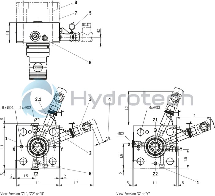
NG40 … 63
With spool position monitoring (2 position switch "Q7", position monitoring "closed" and "open")
(not with version "450")
Dimensions in mm
|
1 |
Name plate |
|
2 |
Position switch (optional) or blind plug |
|
2.1 |
Position switch "open" ("Q7T") |
|
3 |
Mating connector (separate order) |
|
4 |
Space required to remove the mating connector |
|
5 |
Sealing by the factory |
|
6 |
Transport lock for control spool (marking K). Don't remove! Loosening or disassembly and assembly only admissible in case of service/repair! |
|
7 |
Standard end/control cover type LFA... (separate order, depends on the basic hydraulic function) |
|
8 |
Valve mounting screws (separate order, see table) |
|
NG |
L1 |
L2 |
L5 |
L6 |
H1 |
H2 1) 2) |
ØD1 |
ØD2 |
ØD3 |
|
|
mm |
mm |
mm |
mm |
mm |
mm |
mm |
mm |
|||
| 40 | 125 | 58 | 56 | 69 | 80 |
29.5 23 |
G 1/8 | G1/4 | 22 | |
| 50 | 140 | 58 | 63.5 | 63.5 | 100 |
42.5 35 |
G 1/8 | G1/4 | 24 | |
| 63 | 180 | 45 | 82.5 | 82 | 110 |
45.5 36 |
G1/4 | G3/8 | 26 | + 1 |
| 1) | Position monitoring "closed" |
| 2) | Position monitoring "open" |
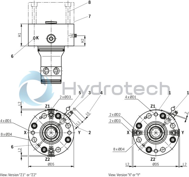
NG80 … 125
With spool position monitoring (1 position switch "Q7", position monitoring "closed")
(version "450" only up to NG100 and pilot oil bore "Z1" and "Z2")
Dimensions in mm
|
1 |
Name plate |
|
2 |
Position switch (optional) or blind plug |
|
3 |
Mating connector (separate order) |
|
4 |
Space required to remove the mating connector |
|
5 |
Sealing by the factory |
|
6 |
Transport lock for control spool (marking K). Don't remove! Loosening or disassembly and assembly only admissible in case of service/repair! |
|
7 |
Standard end/control cover type LFA... (separate order, depends on the basic hydraulic function) |
|
8 |
Valve mounting screws (separate order, see table) |
|
NG |
ØD1 |
ØD2 |
ØD3 1) |
ØD4 |
ØD5 |
L1 |
L2 |
H1 |
H2 |
|
|
mm |
mm |
mm |
mm |
mm |
mm |
mm |
||||
| 80 | G1/2 | G1/2 |
G1 G3/4 |
26 | + 1 | 250 |
37 - |
5 1) 13 1) |
120 | 48 |
| 100 | G1/2 | G1/2 |
G1 G3/4 |
33 | + 0.5 | 300 |
26 - |
5 1) 13 1) |
140 | 55.2 |
| 125 | G3/4 | G1/2 |
G3/4 - |
40 | 380 |
- - |
5 - |
160 | 65.2 | |
| 1) | Version "450" |
NG80 … 125
With spool position monitoring (2 position switch "Q7", position monitoring "closed" and "open")
(not with version "450")
Dimensions in mm
|
1 |
Name plate |
|
2 |
Position switch (optional) or blind plug |
|
2.1 |
Position switch "open" ("Q7T") |
|
3 |
Mating connector (separate order) |
|
4 |
Space required to remove the mating connector |
|
5 |
Sealing by the factory |
|
6 |
Transport lock for control spool (marking K). Don't remove! Loosening or disassembly and assembly only admissible in case of service/repair! |
|
7 |
Standard end/control cover type LFA... (separate order, depends on the basic hydraulic function) |
|
8 |
Valve mounting screws (separate order, see table) |
|
9 |
Connection possibility for a 3rd position switch "closed"(optional, only NG125) |
|
NG |
ØD1 |
ØD2 |
ØD3 |
ØD4 |
ØD5 |
L1 |
H1 |
H2 1) 2) |
|
|
mm |
mm |
mm |
mm |
mm |
mm |
||||
| 80 | G1/2 | G1/2 | G1 | 26 | + 1 | 250 |
37 - |
120 |
48 37.3 |
| 100 | G1/2 | G1/2 | G1 | 33 | + 0.5 | 300 |
26 - |
140 |
55.2 44.7 |
| 125 | G3/4 | G1/2 | G3/4 | 40 | 380 |
- - |
160 |
65.2 54.5 |
|
| 1) | Position monitoring "closed" |
| 2) | Position monitoring "open" |
|
Valve mounting screws (separate order) |
|||||||
|
NG |
Control cover type LFA |
Hexagon socket head cap screws ISO 4762-10.9-flZn |
|||||
|
420 bar |
450 bar |
Quantity |
Dimensions |
Material number (preferred) |
Tightening torque MA2) in Nm ±10 % |
||
|
420 bar |
450 bar |
||||||
|
16 |
1) |
D, H |
4 |
M8 x 80 |
R913015803 |
30 |
|
|
WE., GW. |
KWMA |
M8 x 85 |
R913004145 |
||||
|
– |
WEM., GWMA20 |
M8 x 95 |
R913015806 |
||||
|
WEM. |
– |
M8 x 110 |
R913015792 |
||||
|
HWM. |
HWM. |
M8 x 140 |
R913018191 |
||||
|
25 |
1) |
D, H, WEM., KWMA |
4 |
M12 x 90 |
R913015617 |
100 |
90 |
|
– |
GWMA20 |
M12 x 130 |
R913015591 |
||||
|
HWM. |
HWM. |
M12 x 140 |
R913015593 |
||||
|
32 |
1) |
D, WEM, KWMA |
4 |
M16 x 110 |
R913015642 |
240 |
220 |
|
H3, H4 |
– |
M16 x 120 |
R913014711 |
||||
|
H1, H2 |
H1, H2 |
M16 x 130 |
R913014713 |
||||
|
– |
GWMA20 |
M16 x 140 |
R913015591 |
||||
|
HWM. |
HWM. |
M16 x 160 |
R913015647 |
||||
|
40 |
1) |
D, WEM, KWMA |
4 |
M20 x 150 |
R913015676 |
480 |
430 |
|
– |
GWMA20 |
M20 x 180 |
R913014714 |
||||
|
H., HWM. |
H., HWM. |
M20 x 190 |
R913015680 |
||||
|
50 |
1) |
D, WEM, KWMA, GWMA20 |
4 |
M20 x 180 |
R913014714 |
480 |
430 |
|
H., HWM. |
H., HWM. |
M20 x 220 |
R913014716 |
||||
|
63 |
1) |
D, WEM, KWMA, GWMA20 |
4 |
M30 x 210 |
R913015754 |
1600 |
1500 |
|
H., HWM. |
H., HWM. |
M30 x 260 |
R913015758 |
||||
|
80 |
1) |
D, WEM, GWMA20 |
8 |
M24 x 220 |
R913015719 |
800 |
750 |
|
H2, H4 |
H., KWMA |
M24 x 240 |
R913015721 |
||||
|
100 |
D, WE. |
D, GWMA20, KWMA |
8 |
M30 x 260 |
R913015758 |
1600 |
1500 |
|
1) |
H. |
M30 x 280 |
R913015760 |
||||
|
125 |
H., WEM, WE, D |
– |
8 |
M36 x 320 |
R913050473 |
2300 |
– |
| 1) | More available series control covers |
| 2) | Calculated with total friction coefficient μ = 0.09 ... 0.14, adjust incase of modified surfaces |
Notice!
The length of the valve mounting screws of the active logics (intermediate cover) must be selected according to the related control cover type LFA....
Screw type, screw length and tightening torque are to be adjusted to the conditions depending on the application.
For reasons of stability, exclusively the following valve mounting screws may be used:
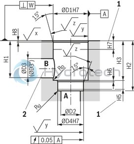
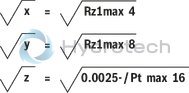
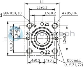
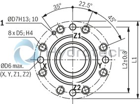
Installation bore and connection dimensions according to ISO 7368
Dimensions in mm
 |
|
Required surface quality of the valve contact surface |
|
1 |
Depth of fit |
|
2 |
Port B may be positioned around the central axis of port A. However, it must be observed that the mounting bores and the pilot oil bores are not damaged. |
NG16 ... 63
Dimensions in mm
|
1 |
Bore for locating pin |
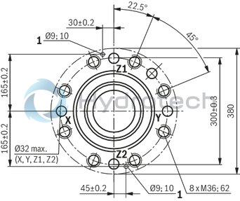
NG80 and 100
Dimensions in mm
|
1 |
Bore for locating pin |
NG125
Dimensions in mm
|
1 |
Bore for locating pin |
Notes:
All information on the mounting bore D5 is based on the use of hexagon socket head cap screws according to ISO 4762. Installation see assembly instructions 21040-MON.|
NG |
ØD1H7 |
ØD2 |
ØD3/ØD3* 1) |
ØD4H7 |
ØD5 |
ØD6 |
ØD7H13 |
H1 |
H2 |
H3 |
H4 |
H5 |
H6 |
H7 |
H8 |
H9 |
L1 |
L2 |
L3 |
L4 |
L5 |
Ro 2) |
Ru 2) |
||||
|
mm |
mm |
mm |
mm |
mm |
mm |
mm |
mm |
mm |
mm |
mm |
mm |
mm |
mm |
mm |
mm |
mm |
mm |
mm |
mm |
mm |
mm |
mm |
mm |
mm |
mm |
||
| 16 | 32 | 16 |
16 25 |
25 | M8 | 4 | 4 | 42.5 | 56 | + 0.1 | 43 | ± 0.2 | 20 | 11 | 2 | 20 | 2 | 0.5 |
80 - |
46 - |
23 | 25 | 10.5 | 2 | 1 | ||
| 25 | 45 | 25 |
25 32 |
34 | M12 | 6 | 6 | 57 | 72 | + 0.1 | 58 | ± 0.2 | 25 | 12 | 2.5 | 30 | 2.5 | 1 |
85 - |
58 - |
29 | 33 | 16 | 2 | 1 | ||
| 32 | 60 | 32 |
32 40 |
45 | M16 | 8 | 6 | 68.5 | 85 | + 0.1 | 70 | ± 0.2 | 35 | 13 | 2.5 | 30 | 2.5 | 1.5 |
102 - |
70 - |
35 | 41 | 17 | 2 | 1 | ||
| 40 | 75 | 40 |
40 50 |
55 | M20 | 10 | 6 | 84.5 | 105 | + 0.1 | 87 | ± 0.3 | 45 | 15 | 3 | 30 | 3 | 2.5 |
125 - |
85 - |
42.5 | 50 | 23 | 4 | 1 | ||
| 50 | 90 | 50 |
50 63 |
68 | M20 | 10 | 8 | 97.5 | 122 | + 0.1 | 100 | ± 0.3 | 45 | 17 | 3 | 35 | 4 | 2.5 |
140 - |
100 - |
50 | 58 | 30 | 4 | 1 | ||
| 63 | 120 | 63 |
63 80 |
90 | M30 | 12 | 8 | 127 | 155 | + 0.1 | 130 | ± 0.3 | 65 | 20 | 4 | 40 | 4 | 3 |
180 - |
125 - |
62.5 | 75 | 38 | 4 | 1 | ||
| 80 | 145 | 80 |
80 100 |
110 | M24 | 16 | 10 | 170.5 | 205 | + 0.1 | 175 | ± 0.4 | 50 | 25 | 5 | 40 | 5 | 4.5 |
250 - |
200 - |
- | - | - | 4 | 1 | ||
| 100 | 180 | 100 |
100 125 |
135 | M30 | 20 | 10 | 205.5 | 245 | + 0.1 | 210 | ± 0.4 | 63 | 29 | 5 | 50 | 5 | 4.5 |
300 - |
245 - |
- | - | - | 4 | 1 | ||
| 125 | 225 | 150 |
125 160 |
200 | - | - | - | 255 | 300 | + 0.15 | 257 | ± 0.5 | - | 31 | 7 | ± 0.5 | 50 | 5.5 | ± 0.2 | 2 |
- - |
- - |
- | - | - | 4 | 1 |
| 1) | Due to the use of a bore with ØD3*, port B protrudes over the upper limit of the area intended in ISO 7368. This is, however, possible due to the sealing concept and reduces the pressure loss during flow through the valve. Thus, we recommend a bore with ØD3*. |
| 2) | Maximum dimension |
Mating connectors for sensors and valves with connector “K24”, “K35” and “K72”, M12 x 1
4P Z24
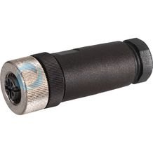
Mating connectors for sensors and valves with connector “K24”, “K35” and “K72”, M12 x 1
4P Z24
For sensors and valves with connector “K24”, “K35” and “K72” Mating connectors M12, 4-pole, line cross-section 0.75 mm2Data sheet
Spare parts & repair