
BOSCH REXROTH
4WE6D5X/BG12-12NXHZ2/V
R901344110
Directional Spool Valves
Directional spool valves: WE 6.-5x/
BOSCH REXROTH
MATERIAL: R901344110
SUMMARY: Directional spool valves: WE 6.-5x/
Quantity in stock: 0
Directional valves of type WE are solenoid-actuated directional spool valves. They control the start, stop and direction of a fluid flow.
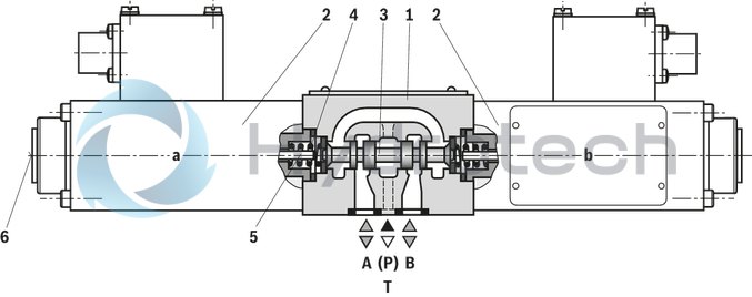
The directional valves basically consist of the housing (1), one or two solenoids (2), the control spool (3), and one or two return springs (4).
In the de-energized condition, the control spool (3) is held in the central position or in the initial position by the return springs (4) (except for impulse spools). The control spool (3) is actuated by wet-pin
solenoids (2).
To ensure proper functioning, make sure that the pressure chamber of the solenoid is filled with oil.
The force of the solenoid (2) acts via the plunger (5) on the control spool (3) and pushes the latter from its rest position to the required end position. This enables the necessary direction of flow from P → A and B → T or P → B and
A → T.
After de-excitation of the solenoid (2), the return spring (4) pushes the control spool (3) back to its rest position.
A manual override (6) allows control spool (3) to be moved without solenoid energization.
Type 4WE 6.. 5X/O...X (only possible with symbols A, C and D)
This version is a directional valve with two spool positions and two solenoids without detent. In the de-energized condition, there is no defined spool position.
Notice:
The tank line must not be allowed to run empty. With corresponding installation conditions, a preload valve (preload pressure approx. 2 bar) is to be installed.
Throttle insert (valve type 4WE 6..5X/…X.../B.. )
The use of a throttle insert is required when due to prevailing operating conditions, flows can occur during the switching processes, which exceed the performance limit of the valve.
It is inserted in channel P of the directional valve.
Example: Type 4WE 6 E5X/.B.X.K20L/..
|
01 |
02 |
03 |
04 |
05 |
06 |
07 |
08 |
09 |
10 |
11 |
12 |
|||
|
WE |
6 |
5X |
/ |
B |
N |
XH |
/ |
|
01 |
3 main ports |
3 |
|
4 main ports |
4 |
|
|
02 |
Size 6 |
6 |
|
03 |
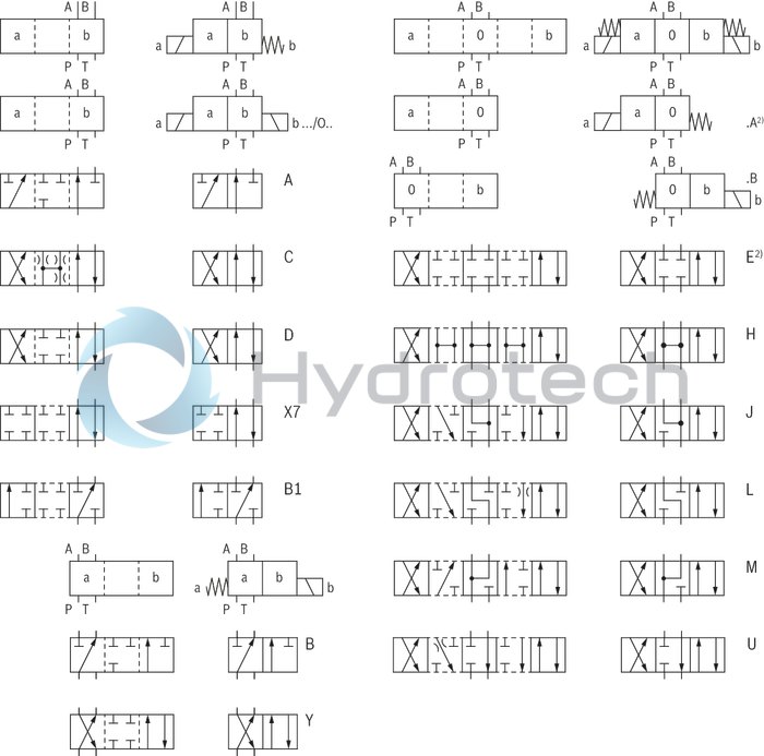
Control spool symbol e. g. C, E, EA, EB etc. possible versions see Symbols |
|
|
04 |
Component series 50 … 59 (50 … 59: unchanged installation and connection dimensions) |
5X |
|
05 |
Spring return |
no code |
|
Without spring return |
O |
|
|
06 |
High-power solenoid, wet (wet-pin) |
B |
|
07 |
Solenoid, direct voltage 12 V |
|
|
Nominal power supply 120 mA |
G12–12 |
|
|
Nominal power supply 130 mA |
G12–13 |
|
|
Nominal power supply 190 mA |
G12–19 |
|
|
depending on the electrical connection, see Information on explosion protection |
||
|
08 |
with manual override (standard) |
N |
|
09 |
“Intrinsically safe” explosion protection for device group II (all except for mining) |
XH |
|
For details, please refer to the explosion protection information |
||
|
Electrical connection |
||
|
10 |
Solenoid with 2 m connection line |
CKL |
|
Solenoid with terminal box and cable gland |
Z2 |
|
|
Solenoid with connector |
K20L |
|
|
For details, please refer to Electrical connection |
||
|
11 |
Without throttle insert |
no code |
|
Throttle Ø 0,8 mm |
B08 |
|
|
Throttle Ø 1,0 mm |
B10 |
|
|
Throttle Ø 1.2 mm |
B12 |
|
|
Use if flow > performance limit of the valve |
||
|
12 |
NBR seals |
no code |
|
FKM seals |
V |
|
|
Observe compatibility of seals with hydraulic fluid used. |
||
Notice:
For possible combinations of the ordering codes for "Solenoid", "Electrical connection" and "Explosion protection”, please refer to the “Information on explosion protection” table.
included in the scope of delivery:
Valve operating instructions with declaration of conformity in part III
general
|
Size |
6 | ||
|
Weight |
Valve with one solenoid |
kg |
2.6 |
|
Valve with two solenoids |
kg |
4.2 | |
|
Installation position |
any | ||
|
Ambient temperature range |
°C |
-20 … +50 | |
|
Storage temperature range |
°C |
+15 … +30 | |
|
Admissible vibration load 1) |
Hz |
20 ... 2,000 | |
|
Surface protection |
Valve body |
Galvanized | |
|
Solenoid |
Galvanized | ||
|
Thermal conductivity of the subplate (EN-GJS-500-7) |
W/m K |
≥ 38 | |
| 1) | Amplitude 0,05 g2/Hz (10 g RMS) |
hydraulic
|
Size |
6 | ||
|
Maximum surface temperature |
see Information on explosion protection | ||
|
Maximum operating pressure |
Port P |
bar |
210 |
|
Port A |
bar |
210 | |
|
Port B |
bar |
210 | |
|
Port T 1) |
bar |
100 | |
|
Maximum flow |
l/min |
20 | |
|
Hydraulic fluid |
see table | ||
|
Hydraulic fluid temperature range |
NBR seals |
°C |
-20 … +80 |
|
FKM seals |
°C |
-15 … +50 | |
|
Viscosity range |
mm²/s |
2.8 … 500 | |
|
Maximum admissible degree of contamination of the hydraulic fluid 2) |
Class 20/18/15 according to ISO 4406 (c) | ||
| 1) | With symbols A and B, port T must be used as leakage oil connection if the operating pressure exceeds the admissible tank pressure. |
| 2) | The cleanliness classes specified for the components must be adhered to in hydraulic systems. Effective filtration prevents faults and simultaneously increases the life cycle of the components. For the selection of the filters, see www.boschrexroth.com/filter. |
|
Hydraulic fluid |
Classification |
Suitable sealing materials |
Standards |
|
|
Mineral oil |
HL, HLP |
FKM, NBR |
DIN 51524 |
|
|
Bio-degradable |
Insoluble in water |
HEES (synthetic esters) |
FKM |
VDMA 24568 |
|
HETG (rape seed oil) |
FKM, NBR |
|||
|
Soluble in water |
HEPG (polyglycols) |
FKM |
VDMA 24568 |
|
|
Containing water |
Containing water |
HFC 1) |
NBR |
ISO 12922 |
|
Other hydraulic fluids on request |
||||
|
Ignition temperature > 130 °C |
||||
| 1) Only in connection with NBR seals. For more information, please ask our sales staff. |
|
Special application conditions for a safe application |
In case of valves with two solenoids, maximally one of the solenoids may be energized at a time. |
electrical
|
Nominal voltage |
12 V | ||||
|
Voltage type |
Direct voltage | ||||
|
Admissible residual ripple |
% |
< 5 | |||
|
Voltage tolerance (nominal voltage) |
% |
± 10 | |||
|
Duty cycle 1) |
% |
100 | |||
|
Rated current |
mA |
120 | 130 | 190 | |
|
Coil resistance with solenoid temperature 20 °C [68 °F] |
Ω |
89 | 59 | ||
|
Minimum current for achieving the hydraulic switching power |
mA |
88 | 96 | 143 | |
|
Switch-off voltage peak of solenoid (max.) |
V |
- 3 | |||
|
Switching time according to ISO 6403 |
ON |
ms |
145 | 105 | |
|
OFF |
ms |
80 | 100 | ||
|
Protection class according to DIN EN 60529 2) |
IP65 | ||||
| 1) | Operating mode according to VDE 0580 |
| 2) | With correctly installed electrical connection |
Information on explosion protection
|
Type |
G12-12 | G12-13 | G12-19 | |||
|
Area of application according to directive 2014/34/EU |
II 2G | - | ||||
|
Type of protection valve |
c (EN 13463-5) | - | ||||
|
Maximum surface temperature 1) |
°C |
80 | - | |||
|
Temperature class |
T6 | - | ||||
|
Type of protection valve solenoid according to EN 60079-0:2009 / EN 60079-11:2007 |
Ex ib IIC T6 Gb | - | ||||
|
Baumusterprüfbescheinigung Magnet |
BVS 08 ATEX E 023 | - | ||||
|
“IECEx Certificate of Conformity” for solenoid |
IECEx BVS 07.0008 | - | ||||
|
Safety-related maximum values of the solenoids dependent on the device group and the type of the electrical connection |
Electrical connection CKL |
Maximum voltage Ui |
Version not available | 27 V DC | Version not available | |
|
Maximum current Ii |
Version not available | 2 A | Version not available | |||
|
Maximum input power P |
Version not available | 3 W | Version not available | |||
|
Electrical connection Z2 |
Maximum voltage Ui |
VDC |
27 | Version not available | ||
|
Maximum current Ii |
A |
2 | Version not available | |||
|
Effective inner inductivity Li |
neglectable | Version not available | ||||
|
Effective inner capacity Ci |
neglectable | Version not available | ||||
|
Electrical connection K20L |
Maximum voltage Ui |
Version not available | ||||
|
Maximum current Ii |
Version not available | |||||
|
Effective inner inductivity Li |
Version not available | |||||
|
Effective inner capacity Ci |
Version not available | |||||
| 1) | Surface temperature > 50 °C, provide contact protection. |
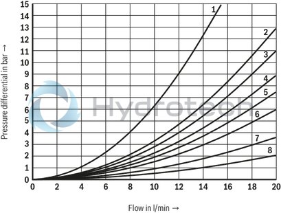
(measured with HLP46, ϑOil = 40 °C ± 5 °C and p = 100 bar)
Δp-qV characteristic curves
|
Symbols |
Direction of flow |
|||
|
P–A |
P–B |
A–T |
B–T |
|
|
A,B |
3 |
3 |
‒ |
‒ |
|
C |
6 |
6 |
6 |
6 |
|
D,Y |
1 |
1 |
4 |
4 |
|
E |
3 |
3 |
7 |
7 |
|
H |
8 |
8 |
7 |
7 |
|
J |
3 |
3 |
7 |
7 |
|
L |
3 |
3 |
7 |
5 |
|
M |
8 |
8 |
4 |
5 |
|
U |
3 |
3 |
5 |
7 |
|
B1 |
2 |
2 |
‒ |
‒ |
|
X7 |
3 |
‒ |
‒ |
3 |
Performance limits
(measured with HLP46, ϑOil = 40 ±5 °C)
Notice:
The specified performance limits are valid for use with two directions of flow (e. g. from P → A and simultaneous return flow from B → T).
Due to the flow forces acting within the valves, the admissible performance limit may be considerably lower with only one direction of flow (e. g. from P → A while port B is blocked)!
In such use cases, please consult us!
The performance limits were determined when the solenoids were at operating temperature, at 10 % undervoltage and without tank preloading.
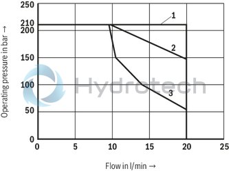
|
DC solenoid |
|
|
Characteristic curve |
Symbol |
|
1 |
D, Y, A, B, C, E, H, J, L, M, U |
|
2 |
X7 |
|
3 |
B1 |
| 2) Example: Control spool symbol E with spool position "a" → ordering code ..EA.. |
The type-examination tested valve solenoid of the valve is equipped with an electrical connection according to the following table. The electrical connection of the solenoids is polarity-independent.
|
Ordering code for the electrical connection |
Type of connection Description |
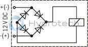
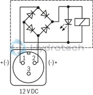
Circuit diagram |
Ordering code for the solenoid, availability |
|
CKL |
Electrical connection via non-exchangeable, two-core connection line, blue Operating display via light emitting diode (LED), red |
|
G12–13 (130 mA) G12–19 (190 mA) |
|
Connection line, two-core |
|||
|
Line cross-section |
0.75 mm2 finely stranded |
||
|
Line diameter |
approx. 5.6 mm |
||
|
Length |
2 m |
||
|
Z2 |
Electrical connection via 2-pole terminal in terminal box with cable gland without operating display |
|
G12–12 (120 mA) |
|
Cable gland |
|||
|
Threaded connection |
M20x1,5 |
||
|
Line diameter |
6,5 ... 9,5 mm1) |
||
|
Sealing |
Outer sheath sealing |
||
|
Connection terminal solenoid |
|||
|
For line cross-section |
0,75 ... 1,5 mm2 |
||
|
K20L |
Electrical connection via connector, 3-pole with pin contacts, type 845-11-1125-001, FCI/Souriau Operating display via light emitting diode (LED), red Suitable mating connector, type 845-11-8522-001, FCI/Souriau, must be ordered separately. |
|
G12–19 (190 mA) |
1) Larger diameters upon request
Type WE 6../.B.X.K20L/...
Dimensions in mm
|
7 |
red LED for displaying the operating state, or plug screw |
|
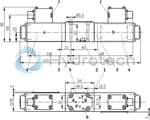
1 |
Name plate |
|
2 |
Same seal rings for ports A, B, P, T |
|
3 |
Cover for valves with one solenoid |
|
4 |
Valve solenoid |
|
5 |
Porting pattern according to ISO 4401-03-02-0-05 |
|
6 |
Receiving hole for locating pin according to ISO 4401-03-02-0-05, (locating pin must be ordered separately, mat. no. R900005694) |
|
7 |
red LED for displaying the operating state, or plug screw |
Valve mounting screws
For reasons of stability, exclusively the following valve mounting screws are to be used:
4 hexagon socket head cap screws
ISO 4762-M5x50-10.9-flZn-240h-L
(friction coefficient 0.09 - 0.14 according to VDA 235-101)
Mat. no. R913000064
(must be ordered separately)
Subplates
(without locating hole)
G 341/01 FE/ZN (G1/4)
G 342/01 FE/ZN (G3/8)
G 502/01 FE/ZN (G1/2)
(with locating hole)
G 341/60 FE/ZN (G1/4)
G 342/60 FE/ZN (G3/8)
G 502/60 FE/ZN (G1/2)
with dimensions as in the data sheet 45052
(must be ordered separately)
Notice:
Subplates are no components in the sense of directive 94/9/EC and can be used after an assessment of the risk of ignition by the manufacturer of the overall system.
The G...FE/ZN versions are free from aluminum and/or free from magnesium and galvanized.
Type WE 6../.B.X.CKL/...
(readily assembled with 2 x 2 m connection line)
Dimensions in mm
|
7 |
red LED for displaying the operating state, or plug screw |
|
1 |
Name plate |
|
2 |
Same seal rings for ports A, B, P, T |
|
3 |
Cover for valves with one solenoid |
|
4 |
Valve solenoid |
|
5 |
Porting pattern according to ISO 4401-03-02-0-05 |
|
6 |
Receiving hole for locating pin according to ISO 4401-03-02-0-05, (locating pin must be ordered separately, mat. no. R900005694) |
|
7 |
red LED for displaying the operating state, or plug screw |
Type WE 6../.B.X.Z2/...
(with terminal box and cable gland)
Dimensions in mm
|
7 |
red LED for displaying the operating state, or plug screw |
Installation conditions
Dimensions in mm