
BOSCH REXROTH
2WRCE32S650L-2X/PG24K31/C1WK15V
R901402694
High-Response Directonal Valves
Throttle control valves: 2WRC* 32.-2x/P
BOSCH REXROTH
MATERIAL: R901402694
SUMMARY: Throttle control valves: 2WRC* 32.-2x/P
Due to extremely high demand, please call 888-651-5712 for availability
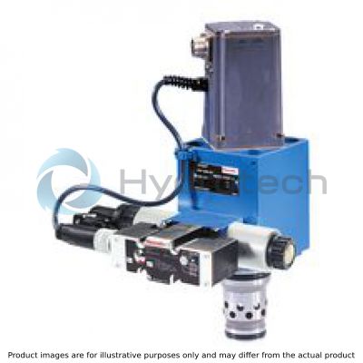
Valves of type 2WRCE are 3-stage high-response valves. They control the quantity and direction of a flow and are mainly used in control loops.
Set-up
They consist of the following assemblies:
the pilot control valve (1) as 1-stage proportional valve (pilot), with two solenoids as electro-mechanical converters and a control spool that is connected to the integrated pilot electronics via electrical feedback (6.2). the second stage (2) for flow control an inductive position transducer (3) the core (4) of which is attached to the spool (5) of the third stage and integrated control electronics (6.1).
Function
The integrated electronics (OBE) compares command and actual values and the solenoids of the pilot control valve are actuated with a proportional current according to the control deviation.
The pilot control valve takes a proportionally controlled position and controls the flow in and out of the control chambers A (7) and B (8) that actuate the main spool (5) through the closed valve control loop up to 0 control deviation.
This means that the stroke of the main spool is regulated proportionally to the command value. It must be noted that the flow also depends on the valve pressure drop.
Valve particularities
The flow can pass through the valve from A to B or from B to A.
The seat spool closes or opens at 5 % of the command value. At lower command values, the valve control loop attempts to guide the spool and thus presses it onto the seat at full pilot pressure and blocks the connection in a leak-free way.
The specified valve dynamics only apply to the control area of the valve. At command value steps from the seat to lower opening values, additional delay times occur.
The opening point of 5 % (= 0.5 V or 0.5 mA) is set at the factory. Upon exchange of the pilot control valve or the controller, normally no settings have to be made.
During the exchange, no settings must be made at the control electronics (= controller or control electronics) and the pilot control valve, except for the zero adjustment at the position transducer.
If required, you can, however, readjust the pilot zero point after a pilot exchange using R321 or the zero point of the complete valve in case of controller exchange using R316
Due to the internal setting of the pilot control valve, the pilot pressure is connected to control chamber B (8) in case of a power failure, i.e. the main stage is closed.
The control electronics feature an offset to compensate the trimming of the pilot control valve (pilot trimming).
Due to differences in diameter in the seat range, the spools are statically not pressure-compensated. To compensate the force differential, 6%/22% of the system pressure at spool “S...L”/”S...R” is required as pilot pressure. With reserves for flow force and dynamics, this defines the recommended minimum pilot pressure (see technical data).

|
01 |
02 |
03 |
04 |
05 |
06 |
07 |
08 |
09 |
10 |
11 |
12 |
13 |
14 |
|||
|
2 |
WRCE |
S |
‒ |
2X |
/ |
P |
G24 |
K31 |
/ |
* |
|
01 |
2/2 directional valve |
2 |
|
|
02 |
Electrically operated high-response valve for block installation with integrated electronics (OBE) |
WRCE |
|
|
03 |
Size 32 |
32 |
|
|
Size 40 |
40 |
||
|
Size 50 |
50 |
||
|
04 |
Seat control spool |
S |
|
|
Rated flow at 5 bar valve pressure drop |
|||
|
05 |
Size 32 |
650 l/min linear |
650 |
|
480 |
|||
|
Size 40 |
1000 l/min linear only ...S1000L... |
1000 |
|
|
700 l/min with fine control range only ...S700R... |
700 |
||
|
Size 50 |
1600 l/min linear only ...S1600L... |
1600 |
|
|
1100 l/min with fine control range only ...S1100R... |
1100 |
||
|
Characteristic curve form |
|||
|
06 |
Linear |
L |
|
|
Linear with progressive fine control range |
R |
||
|
07 |
Component series 20 ... 29 (20 ... 29: unchanged installation and connection dimensions) - Size 6 |
2X |
|
|
Pilot control valve |
|||
|
08 |
Proportional valve |
P |
|
|
09 |
Supply voltage 24 VDC |
G24 |
|
|
Electrical connection |
|||
|
10 |
Without mating connector, with connector according to DIN EN 175301-804, separate order |
K31 |
|
|
Electrical interface |
|||
|
11 |
Command value 0 ...+10 V, actual value 0.5 ...+10 V |
A1 |
|
|
Command value 0 ...+10 mA, actual value 0.5 ...+10 mA |
C1 |
||
|
Sandwich plate shut-off valve |
|||
|
12 |
Without shut-off valve |
no code |
|
|
With shut-off valve |
|||
|
De-energized shut-off valve actively closes “2WRC” with applied pilot pressure |
WK15 |
||
|
De-energized shut-off valve actively opens “2WRC” with applied pilot pressure |
WL15 |
||
|
Seal material |
|||
|
13 |
NBR seals |
M |
|
|
FKM seals |
V |
||
|
14 |
Further details in the plain text |
* |
|
For applications outside these parameters, please consult us!
general
|
Type |
2WRCE.../P | ||||
|
Size |
32 | 40 | 50 | ||
|
Component series |
2X | ||||
|
Installation position |
any, preferably horizontal | ||||
|
Earth |
kg |
12.5 | 19.9 | 26.8 | |
|
Earth |
With shut-off valve |
kg |
13.7 | 21.1 | 28 |
|
Storage temperature range |
°C |
-20 … +80 | |||
|
Ambient temperature range |
°C |
-20 … +50 | |||
|
Sine test according to DIN EN 60068-2-6 |
5...2000 Hz / maximum of 10 g / 10 cycles | ||||
|
Noise test according to DIN EN 60068-2-64 |
20...2000 Hz / 10 gRMS / 30 g peak / 30 min / 3 axes | ||||
|
Transport shock according to DIN EN 60068-2-27 |
15 g / 11 ms | ||||
hydraulic
|
Type |
2WRCE.../P | |||||
|
Size |
32 | 40 | 50 | |||
|
Maximum operating pressure |
bar |
420 | ||||
|
Maximum operating pressure |
Port A |
bar |
420 | |||
|
Port B |
bar |
420 | ||||
|
Maximum operating pressure |
Pilot control valve |
Port X |
bar |
315 | ||
|
Port Y |
bar |
210 | ||||
|
Nominal flow |
Version ...S...L (linear) |
l/min |
650 | 1000 | 1600 | |
|
Version ...S...R (linear with progressive fine control range) |
l/min |
480 | 700 | 1100 | ||
|
Zero flow |
Proportional pre-stage |
min. |

|
|
|
|
|
max. |

|
|
|
|||
|
Minimum pilot pressure |
Control spool S...L |
% |
15 | |||
|
Control spool S...R |
% |
45 | ||||
|
Maximum flow |
l/min |
2000 | 3000 | 4500 | ||
|
Maximum flow |
Control spool S...L |
l/min |
1500 | 2200 | 3500 | |
|
Control spool S...R |
l/min |
2000 | 3000 | 4500 | ||
|
Pilot flow |
l/min |
37 | 45 | 60 | ||
|
Hydraulic fluid temperature range |
°C |
-20 … +80 | ||||
|
preferably |
°C |
+40 … +50 | ||||
|
Viscosity range |
mm²/s |
20 … 380 | ||||
|
preferably |
mm²/s |
30 … 45 | ||||
|
Maximum admissible degree of contamination of the hydraulic fluid, cleanliness class according to ISO 4406 (c) 1) |
Class 20/18/15 according to ISO 4406 (c) | |||||
|
Hysteresis |
% |
≤ 0.2 | ||||
|
Response sensitivity |
% |
≤ 0.1 | ||||
|
Range of inversion |
% |
≤ 0.1 | ||||
|
Closing time 2) |
Pilot control valve |
ms |
≤ 200 | |||
|
Sandwich plate shut-off valve |
ms |
≤ 200 | ||||
| 1) | The cleanliness classes specified for the components must be adhered to in hydraulic systems. Effective filtration prevents faults and simultaneously increases the life cycle of the components. For the selection of the filters, see www.boschrexroth.com/filter. |
| 2) | With pilot pressures from 40 to 315 bar |
|
Hydraulic fluid |
Classification |
Suitable sealing materials |
Standards |
|
Mineral oils and related hydrocarbons |
HL, HLP, HLPD, HVLP, HVLPD |
NBR / FKM |
DIN 51524 |
|
Flame-resistant - containing water |
HFC (Fuchs, Hydrotherm 46M, Petrofer Ultra Safe 620) |
NBR |
ISO 12922 |
|
Important information on hydraulic fluids: For more information and data on the use of other hydraulic fluids please contact us. The flash point of the process and operating medium used must be 40 K over the maximum solenoid surface temperature. There may be limitations regarding the technical valve data (temperature, pressure range, life cycle, maintenance intervals, etc.). |
Flame-resistant - containing water: |
||
electrical
|
Type |
2WRCE.../P | ||
|
Voltage type |
Direct voltage | ||
|
Type of signal |
analog | ||
|
Protection class according to DIN EN 60529 |
IP65 (with mating connector mounted and locked) | ||
|
EMC (electro-magnetic compatibility) |
Tested according to EN 61000-6-2:2001 / VDE 0839 part 6-2 and EN 61000-6-3:2001 / VDE 0839 part 6-3 | ||
|
Zero point calibration |
% |
≤ 1 | |
|
Zero shift upon change of |
Hydraulic fluid temperature |
%/10 K |
≤ 0.3 |
|
Operating pressure |
% |
≤ 0.7 | |
|
Pilot pressure |
%/100 bar |
≤ 0.7 | |
measured with HLP32, ϑOil = 40±5 °C
Rated flow at 5 bar valve pressure differential A → B = B → A

Rated flow at 5 bar valve pressure differential A → B = B → A

2WRCE 32...

2WRCE 32...

2WRCE 32...

2WRCE 40...

2WRCE 40...

2WRCE 40...

2WRCE 50...

2WRCE 50...

2WRCE 50...

|
Detailed |
simplified |
Type 2WRCE...-2X/P
|
Type 2WRCE...-2X/P
|
Type 2WRCE...-2X/P...WK15...
|
Type 2WRCE...-2X/P...WK15...
|
Type 2WRCE...-2X/P...WL15...
|
Type 2WRCE...-2X/P...WL15...
|
Nominal command value range:0 ... +10 V (mA) ≙ 0 ... 100 %In the command value range of 0 ... 0.5 V, the actual value remains constant at 0.5 V.In case of a slow command value modification from 0.5 V ... +10 V, the actual value follows the command value within ±0.15 V. With command values of more than +10 V, the actual value will follow to approx. +12 V. At a command value step to +10 V, the actual value can reach short-time values of up to approx. 10.5 V.


|
Pin assignment |
Contact |
Interface A1 |
Interface C1 |
|
Power supply |
A |
24 VDC nominal (18 ... 30 V; Iaverage = 1A, Ipeak = 3 A) |
|
|
B |
0 VDC |
||
|
Measurement zero |
C |
Reference contact F |
|
|
Differential command value input |
D E |
0 to +10 V Input resistance > 100 kΩ |
0 ... +10 mA; load resistance 100 Ω |
|
Actual value Reference is pin C |
F |
+0,5 ... +10 V; maximal 10 mA |
+0.5 ... +10 mA; load resistance maximum 1 kΩ |
|
PE |
connected to valve housing; do not connect if the valve has already been grounded via the system |
||
Command value and actual value have the same polarity. In case of failure of the fuse “1 A fast”, the actual value may temporarily also be measured between F and B.
Notice:
Electrical signals provided via control electronics (e.g. actual value) must not be used to switch off safety-relevant machine functions!
(See also the European standard "Safety requirements for fluid-powered systems and their components - Hydraulics", EN 982.)
Size 32

|
1 |
Pilot control valve (proportional directional valve NG6) |
|
2 |
Sandwich plate shut-off valve (only with versions “WK15” and “WL15”) |
|
3 |
Socket |
|
4 |
Mating connector according to DIN EN 175201-804, separate order |
|
5 |
Mating connector according to DIN EN 175301-803, separate order |
|
6 |
Space required to remove the mating connector |
|
7 |
Cabling |
|
8 |
Valve mounting screws (included in the scope of delivery): |
|
9 |
Locking pin for locating hole |
|
10 |
Identical seal rings for ports X and Y |
|
11 |
Name plate |
NG40

|
1 |
Pilot control valve (proportional directional valve NG6) |
|
2 |
Sandwich plate shut-off valve (only with versions “WK15” and “WL15”) |
|
3 |
Socket |
|
4 |
Mating connector according to DIN EN 175201-804, separate order |
|
5 |
Mating connector according to DIN EN 175301-803, separate order |
|
6 |
Space required to remove the mating connector |
|
7 |
Cabling |
|
8 |
Valve mounting screws (included in the scope of delivery): |
|
9 |
Locking pin for locating hole |
|
10 |
Identical seal rings for ports X and Y |
|
11 |
Name plate |
NG50

|
1 |
Pilot control valve (proportional directional valve NG6) |
|
2 |
Sandwich plate shut-off valve (only with versions “WK15” and “WL15”) |
|
3 |
Socket |
|
4 |
Mating connector according to DIN EN 175201-804, separate order |
|
5 |
Mating connector according to DIN EN 175301-803, separate order |
|
6 |
Space required to remove the mating connector |
|
7 |
Cabling |
|
8 |
Valve mounting screws (included in the scope of delivery): |
|
9 |
Locking pin for locating hole |
|
10 |
Identical seal rings for ports X and Y |
|
11 |
Name plate |
NG32 to 50

Installation bore according to ISO 7368

|
1 |
Depth of fit, minimum dimension |
|
2 |
The ports P, T and B can be positioned around the central axis of port A. Sufficient distance from the mounting and control bores is to be observed |
|
3 |
Bore for locating pin |
|
Tolerances according to ISO 2768-mK |
|
NG |
ØD1H7 |
ØD2H7 |
ØD3H7 |
ØD4 |
ØD5 |
ØD6H7 |
ØD7 |
D8 |
max. ØD9 |
ØD10 |
H1 |
H2 |
H3 |
H4 |
H5 |
H7 |
H8 |
H9 |
H10 |
H11 |
H12 |
H13 |
H16 |
H17 |
H18 |
L1 |
L2 |
L3 |
L4 |
L5 |
|
mm |
mm |
mm |
mm |
mm |
mm |
mm |
mm |
mm |
mm |
mm |
mm |
mm |
mm |
mm |
mm |
mm |
mm |
mm |
mm |
mm |
mm |
mm |
mm |
mm |
mm |
mm |
mm |
mm |
||
| 32 | 60 | 58 | 55 | 32 | 24 | 45 | 32 | M16 | 8 | 6 | 70 | 85 | 52 | 30 | 13 | 43.5 | 85 | 100 | 30 | 70.5 | 18 | 15 | 2.5 | 2.5 | 35 | 105 | 70 | 35 | 41 | 17 |
| 40 | 75 | 73 | 55 | 40 | 30 | 55 | 40 | M20 | 10 | 6 | 87 | 105 | 64 | 30 | 15 | 54 | 105 | 125 | 36 | 87 | 21 | 18 | 3 | 3 | 45 | 125 | 85 | 42.5 | 50 | 23 |
| 50 | 90 | 87 | 68 | 50 | 35 | 68 | 50 | M20 | 10 | 8 | 100 | 122 | 72 | 35 | 17 | 87 | 143 | 165 | 66 | 122 | 48 | 18 | 4 | 3 | 45 | 140 | 100 | 50 | 58 | 30 |
Mating connectors for valves with connector “K4”, without circuitry, standard
3P Z4
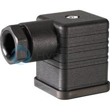
Mating connectors for valves with connector “K4”, without circuitry, standard
3P Z4
For valves with connector “K4” according to EN 175301-803 and ISO 4400, 2-pole + PE, “large cubic connector” Mating connectors for valves with one or two solenoids (individual connection)Data sheet
Spare parts & repair
Mating connectors for valves with round connector, 6-pole + PE
7P Z31
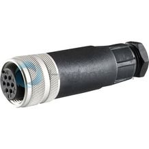
Mating connectors for valves with round connector, 6-pole + PE
7P Z31
For valves with round connector according to EN 175201-804, 6-pole + PE as well as 6-pole, compatible with VG 95328Data sheet
Spare parts & repair