
BOSCH REXROTH
Z2DB6DD2-2X/100V
R901423505
Pressure Relief Valves
Pressure valves: ZDB 6D.-2X
BOSCH REXROTH
MATERIAL: R901423505
SUMMARY: Pressure valves: ZDB 6D.-2X
Quantity in stock: 0
Pressure valves of type ZDB6D and Z2DB6D are direct operated pressure relief valves in sandwich plate design.
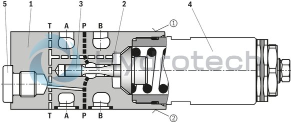
The valves basically consist of housing (1) with seat (2) and control spool (3). The system pressure is set via the adjustment type (4).
The valves are closed in their rest position and protect a hydraulic system and its components against excessive pressures.
These valves respond quickly, noiselessly and in a virtually leakage-free manner. Thanks to the seat design, they are resistant against oil contamination. The integrated damping of the control spool (3) ensures extremely stable behavior,
as well as a low pressure increase with increasing flow.
In the state as delivered, the valves are set to the minimum possible pressure. The system pressure applied to channel P acts on the control spool (3). If the system pressure increases above the set value, the control spool (3) opens and the hydraulic fluid flows from channel P in channel T. This limits the system pressure to the set value.
For versions “MP”, “MA” and “MB”, the set system pressure can be recorded and monitored using a pressure load cell at the measuring port (5) (see dimensions)
Type ZDB 6 DP2 …MP…
|
➀ |
component side |
|
➁ |
plate side |
|
01 |
02 |
03 |
04 |
05 |
06 |
07 |
08 |
09 |
10 |
11 |
12 |
||
|
Z |
DB |
6 |
D |
– |
2X |
/ |
|
01 |
Sandwich plate valve |
Z |
|
02 |
1 pressure valve cartridge (only with version “A”, “B” and “P”) |
no code |
|
2 pressure valve cartridges (only with version “C” and “D”) |
2 |
|
|
03 |
Pressure relief valve |
DB |
|
04 |
Size 6 |
6 |
|
05 |
Direct operated |
D |
|
Relief function from – to: |
||
|
06 |
P – T |
P |
|
A – T |
A |
|
|
B – T |
B |
|
|
A – T and B – T |
C |
|
|
A – B and B – A (for possible adjustment types/pressure ratings, see below) |
D |
|
|
Adjustment type |
||
|
07 |
Rotary knob |
1 |
|
Spindle with hexagon |
2 |
|
|
Lockable rotary knob with scale 1) |
3 |
|
|
08 |
Component series 20 ... 29 (20 ... 29: unchanged installation and connection dimensions) |
2X |
|
Pressure rating |
||
|
09 |
Set pressure up to 50 bar |
50 |
|
Set pressure up to 100 bar |
100 |
|
|
Set pressure up to 200 bar |
200 |
|
|
Set pressure up to 350 bar |
350 |
|
|
Pressure measuring port G1/4 |
||
|
10 |
Without pressure measuring port |
no code |
|
With pressure measuring port in port P (version “P” only) |
MP |
|
|
With pressure measuring port in port A (version “A” only) |
MA |
|
|
With pressure measuring port in port B (version “B” only) |
MB |
|
|
Corrosion resistance |
||
|
11 |
None |
no code |
|
Improved corrosion protection (240 h salt spray test according to EN ISO 9227); (only version "2") |
J3 |
|
|
Seal material |
||
|
12 |
NBR seals |
no code |
|
FKM seals |
V |
|
|
Observe compatibility of seals with hydraulic fluid used. (Other seals upon request) |
||
| 1) | Key with material no. R900008158 is included in the scope of delivery. |
|
Version “DD” |
||||
|
Adjustment type |
Pressure rating |
|||
|
„50“ |
„100“ |
„200“ |
„350“ |
|
|
“1” and “2” |
✔ |
✔ |
✔ |
– |
|
„3“ |
✔ |
✔ |
– |
– |
Notes:
For valve types for use in potentially explosive areas, refer to data sheet 07011. Preferred types and standard units are contained in the EPS (standard price list).general
|
Type |
ZDB6D | Z2DB6D | ||
|
Weight (approx.) |
Version “1” and “2” |
kg |
1.3 | 2.3 |
|
Version "3" |
kg |
1.4 | 2.4 | |
|
Installation position |
any | |||
|
Ambient temperature range |
°C |
-15 … +80 | ||
hydraulic
|
Pressure rating |
bar |
50 | 100 | 200 | 350 | ||
|
Maximum operating pressure |
Version “P”, “A”, “B”, “C” |
Port A |
bar |
350 | |||
|
Port B |
bar |
350 | |||||
|
Port P |
bar |
350 | |||||
|
Port T 1) |
bar |
200 | |||||
|
Version “D” |
Port A 1) |
bar |
200 | ||||
|
Port B 1) |
bar |
200 | |||||
|
Port P |
bar |
350 | |||||
|
Port T |
bar |
350 | |||||
|
Return flow pressure |
Ideally depressurized to the tank. Counter pressure adds to the set pressure. | ||||||
|
Maximum set pressure |
bar |
50 | 100 | 200 | 350 | ||
|
Pressure change per rotation 2) |
bar |
7 | 14 | 27 | 46 | ||
|
Maximum flow |
l/min |
60 | |||||
|
Hydraulic fluid |
see table | ||||||
|
Hydraulic fluid temperature range |
°C |
-15 … +80 | |||||
|
Viscosity range 3) |
mm²/s |
10 … 500 | |||||
|
Maximum admissible degree of contamination of the hydraulic fluid 4) |
Class 20/18/15 according to ISO 4406 (c) | ||||||
| 1) | Version “1” and “2”; 100 bar version “3” |
| 2) | The information refers to calculated guidelines and is subject to tolerances. Completely unloaded valves may have an idle stroke of up to 2 rotations. |
| 3) | Preferably 50 … 120 mm2/s |
| 4) | The cleanliness classes specified for the components must be adhered to in hydraulic systems. Effective filtration prevents faults and simultaneously increases the life cycle of the components. For the selection of the filters, see www.boschrexroth.com/filter. |
|
Hydraulic fluid |
Classification |
Suitable sealing materials |
Standards |
Data sheet |
|
|
Mineral oils |
HL, HLP |
NBR, FKM |
DIN 51524 |
90220 |
|
|
Bio-degradable |
Insoluble in water |
HETG |
FKM |
ISO 15380 |
90221 |
|
HEES |
FKM |
||||
|
Soluble in water |
HEPG |
FKM |
ISO 15380 |
||
|
Flame-resistant |
Water-free |
HFDU (glycol base) 1) |
FKM |
ISO 12922 |
90222 |
|
HFDU (ester base) |
FKM |
||||
|
Containing water |
HFC (Fuchs Hydrotherm 46M, Petrofer Ultra Safe 620 ) |
NBR |
ISO 12922 |
90223 |
|
|
Important information on hydraulic fluids! For further information and data on the use of other hydraulic fluids, please refer to the data sheets above or contact us! There may be limitations regarding the technical valve data (temperature, pressure range, life cycle, maintenance intervals, etc.)! The ignition temperature of the hydraulic fluid used must be [si]50 K[/si][imp]90 °F[/imp] higher than the maximum solenoid surface temperature.Flame-resistant – containing water: Maximum operating pressure [si]210 bar[si][imp]3050 psi[/imp], otherwise, increased cavitation erosion Life cycle as compared to operation with mineral oil HL, HLP 30 … 100 % Maximum hydraulic fluid temperature [si]60 °C[/si][imp]140 °F[/imp]Bio-degradable and flame-resistant: If these hydraulic fluids are used, small amounts of dissolved zinc may get into the hydraulic system. |
|||||
| 1) | Not recommended for corrosion-protected version "J3" (contains zinc) |
For applications outside these parameters, please consult us!
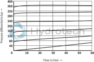
(measured with HLP46, ϑOil = 40 ±5 °C)
∆p-qV characteristic curves
Pressure rating 50 bar
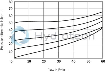
Pressure rating 100 bar
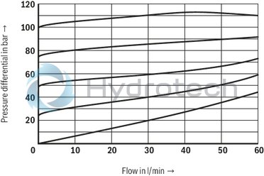
Pressure rating 200 bar
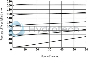
Pressure rating 350 bar
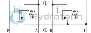
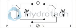
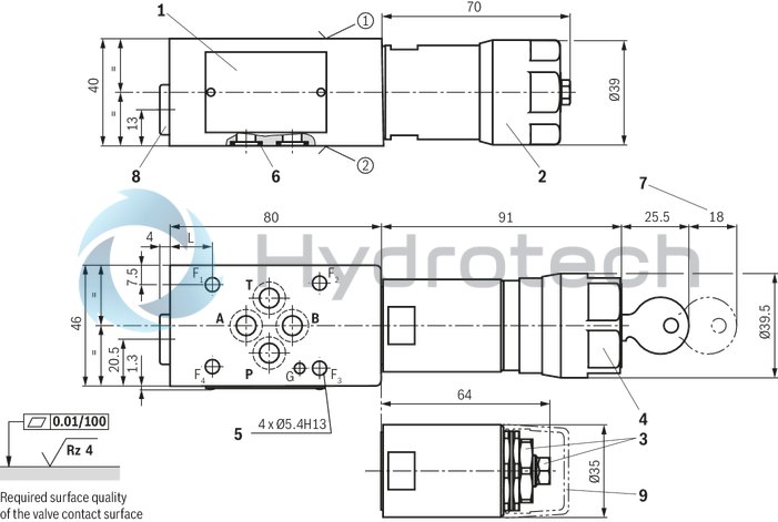
(➀ = component side, ➁ = plate side)
Version “P” (example with “MP”)

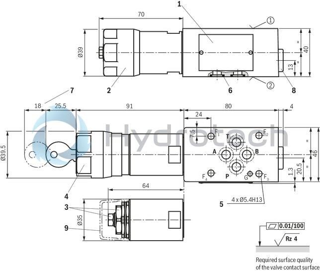
Version “A” (example with “MA”)

Version “B” (example with “MB”)

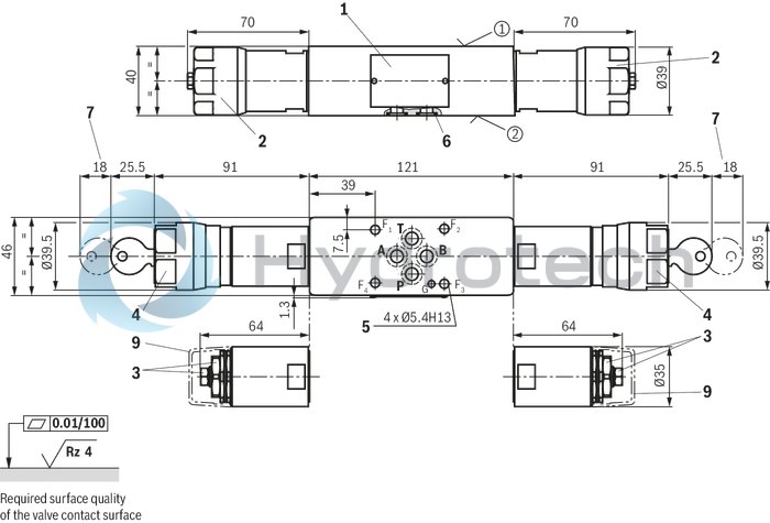
Version "C"
Version “D”
Version “P” and “B”
Dimensions in mm
|
➀ |
component side – porting pattern according to ISO 4401-03-02-0-05 (with locating hole Ø4 x 4 mm deep) |
|
➁ |
plate side – porting pattern according to ISO 4401-03-02-0-05 (with locating hole Ø3 x 5 mm deep for locking pin ISO 8752-3x8-St, separate order, see accessories) |
|
1 |
Name plate |
|
2 |
Adjustment type "1" |
|
3 |
Adjustment type “2” (spindle with external hexagon SW10 and lock nut SW24) |
|
4 |
Adjustment type "3" |
|
5 |
Valve mounting bores |
|
6 |
Identical seal rings for ports A, B, P, T (plate side) |
|
7 |
Space required to remove the key |
|
8 |
Measuring port G1/4 (SW6 internal hexagon, tightening torque MA = 30 Nm ±10 %) |
|
9 |
Protective cap (separate order, see accessories) |
|
Type |
L |
|
|
Version "P" |
Version "B" |
|
|
mm |
mm |
|
| ZDB6D | 16 | 13 |
| Z2DB6D | 16 | 13 |
Valve mounting screws (separate order)
4 hexagon socket head cap screws ISO 4762 - M5 - 10.9
Notes:
Length and tightening torque of the valve mounting screws must be calculated according to the components mounted under and over the sandwich plate valve. The dimensions are nominal dimensions which are subject to tolerances.Version "A"
Dimensions in mm
|
➀ |
component side – porting pattern according to ISO 4401-03-02-0-05 (with locating hole Ø4 x 4 mm deep) |
|
➁ |
plate side – porting pattern according to ISO 4401-03-02-0-05 (with locating hole Ø3 x 5 mm deep for locking pin ISO 8752-3x8-St, separate order, see accessories) |
|
1 |
Name plate |
|
2 |
Adjustment type "1" |
|
3 |
Adjustment type “2” (spindle with external hexagon SW10 and lock nut SW24) |
|
4 |
Adjustment type "3" |
|
5 |
Valve mounting bores |
|
6 |
Identical seal rings for ports A, B, P, T (plate side) |
|
7 |
Space required to remove the key |
|
8 |
Measuring port G1/4 (SW6 internal hexagon, tightening torque MA = 30 Nm ±10 %) |
|
9 |
Protective cap (separate order, see accessories) |
Valve mounting screws (separate order)
4 hexagon socket head cap screws ISO 4762 - M5 - 10.9
Notes:
Length and tightening torque of the valve mounting screws must be calculated according to the components mounted under and over the sandwich plate valve. The dimensions are nominal dimensions which are subject to tolerances.Version "C" and "D"
Dimensions in mm
|
➀ |
component side – porting pattern according to ISO 4401-03-02-0-05 (with locating hole Ø4 x 4 mm deep) |
|
➁ |
plate side – porting pattern according to ISO 4401-03-02-0-05 (with locating hole Ø3 x 5 mm deep for locking pin ISO 8752-3x8-St, separate order, see accessories) |
|
1 |
Name plate |
|
2 |
Adjustment type "1" |
|
3 |
Adjustment type “2” (spindle with external hexagon SW10 and lock nut SW24) |
|
4 |
Adjustment type "3" |
|
5 |
Valve mounting bores |
|
6 |
Identical seal rings for ports A, B, P, T (plate side) |
|
7 |
Space required to remove the key |
|
9 |
Protective cap (separate order, see accessories) |
Valve mounting screws (separate order)
4 hexagon socket head cap screws ISO 4762 - M5 - 10.9
Notes:
Length and tightening torque of the valve mounting screws must be calculated according to the components mounted under and over the sandwich plate valve. The dimensions are nominal dimensions which are subject to tolerances.|
Denomination |
Part number |
|
Protective cap |
R900131744 |
|
Locking pin ISO 8752-3x8-St |
R900005694 |