
BOSCH REXROTH
R901425475
Pressure Switches
Switch HEDE10.3X/
BOSCH REXROTH
MATERIAL: R901425475
SUMMARY: Switch HEDE10.3X/
Quantity in stock: 0
|
01 |
02 |
03 |
04 |
05 |
06 |
07 |
08 |
|||||||
|
HEDE10 |
- |
3X |
/ |
/ |
/- |
- |
- |
- |
* |
|
01 |
Hydro-electric pressure switch |
HEDE10 |
|
02 |
Component series 30 ... 39 (30 ... 39: unchanged installation and connection dimensions) |
3X |
|
03 |
Pressure rating maximum 100 bar |
100 bar |
|
Pressure rating maximum 250 bar |
250 bar |
|
|
Pressure rating maximum 400 bar |
400 bar |
|
|
Pressure rating maximum 600 bar |
600 bar |
|
|
Output |
||
|
04 |
1 switching and 1 analog output |
1 |
|
2 switching outputs |
2 |
|
|
Hydraulic connection |
||
|
05 |
Internal thread G1/4 |
Gi |
|
Male thread G1/4 |
Ga |
|
|
Electrical connection |
||
|
06 |
Individual connection |
|
|
Without mating connector; connector M12 DIN EN 61076-2-101 without cable with M12 connector, A-coded |
K35 1) |
|
|
Seal material |
||
|
07 |
FKM seals 2) |
V |
|
Without seal (with internal thread) |
0 |
|
|
08 |
Further details in the plain text |
* |
| 1) | Mating connectors, separate order, see "Accessories" |
| 2) | Observe compatibility of seals with hydraulic fluid used. (Other seals upon request) |
Accessories
Mating connectors for the electrical connection see chapter Electrical connection. Mounting clamp and protective cap see chapter Accessories.Type
|
Component series |
3X |
General
|
Weight |
m |
kg |
0.26 | |
|
Installation position |
any | |||
|
Ambient temperature range |
ϑ |
°C |
-25 … +80 | |
|
Storage temperature range |
ϑ |
°C |
-40 … +100 | |
|
Sine test according to DIN EN 60068-2-6:1996-05 |
10 ... 2000 Hz, max. 20 g, 10 double cycles | |||
|
Transport shock according to DIN EN 60068-2-27:1995-03 |
Half-sine 50 g / 11 ms, 3 x in positive direction, 3 x negative direction (a total of 18 single shocks) |
|||
|
Noise test according to DIN EN 60068-2-64: 1995-08 |
20...2000 Hz, 10 gRMS, 24 h | |||
|
Conformity |
CE |
DIN EN 60947-1: 2007 / A1: 2011 / A2: 2014 DIN EN 60947-5-1: 2004 / A1: 2009 DIN EN 61058-1: 2002 / A2: 2008 DIN EN 60529: 1991 / A2: 2013 |
||
|
UL |
UL, 508 17th edition File No E223220 (up to 350 bar) | |||
|
Protection class according to DIN EN 60529 |
IP 65 / IP 67 with mating connector mounted and fitted | |||
|
Protection class according to EN 50178 |
III | |||
Hydraulic
|
Pressure measuring ranges |
pN |
bar |
100 | 250 | 400 | 600 | 100 | 250 | 400 | 600 | 100 | 250 | 400 | 600 | 100 | 250 | 400 | 600 | |
|
Overload protection |
pmax |
bar |
300 | 500 | 800 | 300 | 500 | 800 | 300 | 500 | 800 | 300 | 500 | 800 | |||||
|
Bursting pressure |
p |
bar |
400 | 1000 | 1600 | 2500 | 400 | 1000 | 1600 | 2500 | 400 | 1000 | 1600 | 2500 | 400 | 1000 | 1600 | 2500 | |
|
Switching point |
Setting range |
bar |
1 … 100 | 2 … 250 | 4 … 400 | 6 … 600 | 1 … 100 | 2 … 250 | 4 … 400 | 6 … 600 | 1 … 100 | 2 … 250 | 4 … 400 | 6 … 600 | 1 … 100 | 2 … 250 | 4 … 400 | 6 … 600 | |
|
Reset range |
bar |
0.5 … 99.5 | 1 … 249 | 2 … 398 | 3 … 597 | 0.5 … 99.5 | 1 … 249 | 2 … 398 | 3 … 597 | 0.5 … 99.5 | 1 … 249 | 2 … 398 | 3 … 597 | 0.5 … 99.5 | 1 … 249 | 2 … 398 | 3 … 597 | ||
|
In steps of |
bar |
0.5 | 1 | 2 | 3 | 0.5 | 1 | 2 | 3 | 0.5 | 1 | 2 | 3 | 0.5 | 1 | 2 | 3 | ||
|
Druckflüssigkeit 1) |
see table below | ||||||||||||||||||
|
Hydraulic fluid temperature range |
(at the working port of the pressure switch) |
ϑ |
°C |
-25 … +80 | |||||||||||||||
|
Viscosity range |
mm²/s |
10 … 800 | |||||||||||||||||
|
Maximum admissible degree of contamination of the hydraulic fluid, cleanliness class according to ISO 4406 (c) |
Class 20/18/15 1) | ||||||||||||||||||
|
Materials in contact with the medium |
V4A (1.4542), FKM (with male thread) | ||||||||||||||||||
|
Pressure port |
Internal thread "Gi" |
G1/4 | |||||||||||||||||
|
Male thread "Ga" |
G1/4 | ||||||||||||||||||
| 1) | The cleanliness classes specified for the components must be adhered to in hydraulic systems. Effective filtration prevents faults and simultaneously increases the life cycle of the components. For the selection of the filters, see www.boschrexroth.com/filter. |
|
Hydraulic fluid |
Classification |
Suitable sealing materials |
Standards |
Data sheet |
|
|
Mineral oils |
HL, HLP, HLPD, HVLP, HVLPD |
NBR, FKM, low-temperature seals |
DIN 51524 |
90220 |
|
|
Bio-degradable |
⇒Insoluble in water |
HETG |
NBR, FKM |
ISO 15380 |
90221 |
|
HEES |
FKM |
||||
|
⇒Soluble in water |
HEPG |
FKM |
ISO 15380 |
||
|
Flame-resistant |
⇒Water-free |
HFDU, HFDR |
FKM |
ISO 12922 |
90222 |
|
⇒Containing water |
HFC (Fuchs Hydrotherm 46M, Petrofer Ultra Safe 620) |
NBR |
ISO 12922 |
90223 |
|
Important information on hydraulic fluids:
For more information and data on the use of other hydraulic fluids, please refer to the data sheets above or contact us! There may be limitations regarding the technical valve data (temperature, pressure range, life cycle, maintenance intervals, etc.)! The flash point of the hydraulic fluid used must be 40 K higher than the maximum solenoid surface temperature.• Flame-resistant – containing water:
- Maximum pressure differential per control edge 50 bar
- Pressure pre-loading at the tank port >20% of the pressure differential, otherwise increased cavitation
- Life cycle as compared to operation with mineral oil HL, HLP 50 to 100%
• Bio-degradable and flame-resistant:
When using hydraulic fluids that are simultaneously zinc-solving, zinc may accumulate (700 mg zinc per pole tube).
Electric
|
Electrical connection |
M12 plug-in connection, gold-plated contacts | ||||
|
Input variables |
Operating voltage |
UB |
18 … 30 VDC | ||
|
Current consumption |
I |
mA |
< 50 | ||
|
Isolation resistance |
mΩ |
>100 (500 VDC) | |||
|
Output parameters |
Analog output |
Current carrying capacity |
U |
0 ... 10 VDC (minimum load 2000 Ω) | |
|
Voltage |
I |
4 ... 20 mA (max. load (UB – 10) x 50 Ω) | |||
|
Rise time (10 to 90 %) |
t |
ms |
3 | ||
|
Switching output |
Output function |
Normally open contact / normally closed contact programmable | |||
|
Current carrying capacity 1) |
I |
mA |
150 | ||
|
Voltage drop (short-circuit protection clocked) |
U |
V |
< 2.5 | ||
|
Overload-resistant |
yes | ||||
|
Switching frequency |
f |
Hz |
≤ 170 | ||
|
Accuracy / variations |
Characteristic curve deviation 2) |
% |
< ± 0.5 | ||
|
Temperature coefficient |
Zero point and range |
< 0.2 % / 10 K | |||
|
Hysteresis |
% |
< ± 0.25 | |||
|
Switching point accuracy |
% |
< ± 0.5 | |||
|
Repetition accuracy |
% |
0.1 | |||
|
Programming options |
Hysteresis/window; normally open contact/normally closed contact; activation, deactivation delay; damping; indicator unit/diagnosis output | ||||
|
Long-term drift under reference conditions (6 months) |
% |
0.05 | |||
|
EMC (electro-magnetic compatibility) |
EN 61000-4-2 ESD |
kV |
4 / 8 | ||
|
EN 61000-4-3 HF radiated |
V/m |
10 | |||
|
EN 61000-4-4 Burst |
kV |
2 | |||
|
EN 61000-4-5 Surge |
kV |
1 | |||
|
EN 61000-4-6 HF conducted |
V |
10 | |||
|
Reaction times |
Readiness delay time |
s |
0.3 | ||
|
Minimal reaction time switching output |
ms |
<3 | |||
|
Adjustable delay time dS, dr |
s |
0...50 | |||
|
Damping switching output (dAP) |
s |
0...4 | |||
|
Damping analog output (dAA) |
s |
0...4 | |||
|
Rise time analog output |
ms |
< 3 | |||
|
Watchdog integrated |
yes | ||||
|
Switching cycles min. |
100 million / 50 million with pressure rating 600 bar | ||||
|
IO-Link device |
Transmission type |
COM2 (38.4 kBaud) | |||
|
IO-Link revision |
1.1 | ||||
|
SDCI standard |
IEC 61131-9 | ||||
|
Profiles |
Smart Sensor: Process Data Variable; Device Identification, Device Diagnosis |
||||
|
SIO mode |
yes | ||||
|
Required master port class |
A | ||||
|
Process data analog |
1 | ||||
|
Process data binary |
2 | ||||
|
Minimal process cycle time |
ms |
2.3 | |||
|
Display |
Indicator unit |
3 x LED green (bar, psi, MPa) | |||
|
Switching status |
2 x LED yellow | ||||
|
Measured values |
4-digit alphanumerical display / alternating display (red and green) | ||||
| 1) | 200 (...60 °C); 250 (...40 °C) mA |
| 2) | according to end point setting DIN16086 |
For applications outside these parameters, please consult us!

|
1 ... 8: indicator LEDs |
|
|
LED 1 |
Switching status OUT1 (is illuminated when output 1 is switched through) |
|
LED 8 |
Switching status OUT2 (is illuminated when output 2 is switched through) |
|
LED 2 ... 7 1) |
System pressure in the specified unit of measurement |
|
9: Enter key [•] |
|
|
Selection of the parameters and confirmation of the parameter values |
|
|
10 and 11: Arrows up [⇑] and down [⇓] |
|
|
Setting of the parameter values (permanent by continuous pressure; step-wise by pressing individually) |
|
|
12: Alphanumerical display, 4-digit |
|
|
Display of the current system pressure |
|
|
Display of the parameters and parameter values |
|
| 1) | With variant 1 switching and 1 analog output, these LEDs don’t have any function. |
according to DIN EN 175301-803
|
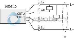
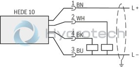
"K35" two switching outputs |
|
|
n-switching (NPN) |
p-switching (PNP) |
 |
 |
|
OUT1: Switching output or IO-Link |
OUT1: Switching output or IO-Link |
|
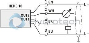
"K35" one switching and one analog output: |
|
 |
|
|
OUT1: Switching output or IO-Link |
|
Connector view at the device:

When establishing the electrical connection, the protective earthing conductor (PE, grounded) must be connected correctly.
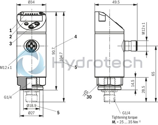
Dimensions in mm
| 1) | Depending on lubrication, seal and pressurization |
|
1 |
Status LEDs |
|
2 |
4-digit alphanumerical display |
|
3 |
Programming button |
|
4 |
Dimension for "Gi" version with internal thread G1/4" |
|
5 |
Dimension for "Ga" version with male thread G1/4" |
Notice:
Oscillation-free installation is recommended.
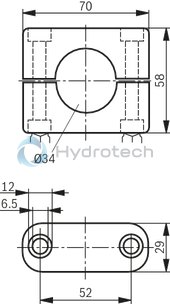
Mounting clamp for HEDE 10
|
Designation |
Material number |
Buy |
| Fastening clamp E10193 | R900786138 | eShop |
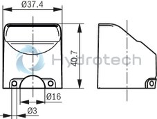
Protective cap for HEDE 10
|
Designation |
Material number |
Buy |
| Protective cap HEDE10-3X | R901453193 | eShop |
Mating connectors for sensors and valves with connector “K24”, “K35” and “K72”, M12 x 1
4P Z24
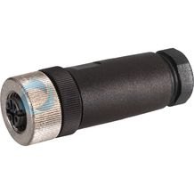
Mating connectors for sensors and valves with connector “K24”, “K35” and “K72”, M12 x 1
4P Z24
For sensors and valves with connector “K24”, “K35” and “K72” Mating connectors M12, 4-pole, line cross-section 0.75 mm2Data sheet
Spare parts & repair
Mating connectors for sensors and valves with connector “K24”, “K35” and “K72”, M12 x 1, with assembled connection line
4P Z24 +
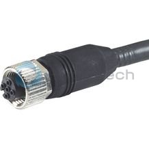
Mating connectors for sensors and valves with connector “K24”, “K35” and “K72”, M12 x 1, with assembled connection line
4P Z24 +
For sensors and valves with connector “K24”, “K35” and “K72” Mating connectors M12, 4-pole, line cross-section 0.75 mm2Data sheet
Spare parts & repair
Mating connectors for sensors and valves with connector “K24”, “K35” and “K72”, M12 x 1, with assembled connection line, cable shielded
4P M12 +
Mating connectors for sensors and valves with connector “K24”, “K35” and “K72”, M12 x 1, with assembled connection line, cable shielded
4P M12 +
For sensors and valves with connector “K24”, “K35” and “K72” Cable sets M12, 4-pole, line cross-section 0.34 mm2Data sheet
Spare parts & repair