
BOSCH REXROTH
AA2FO45/61L-VSD55
R902193248
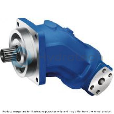
Bent Axis Piston Pumps
Fixed pumps: A2FO, A2F 45cm?/U
BOSCH REXROTH
MATERIAL: R902193248
SUMMARY: Fixed pumps: A2FO, A2F 45cm?/U
Quantity in stock: 0
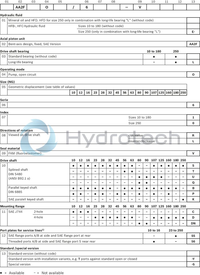
Table of values
|
Size |
10 | 12 | 16 | 23 | 28 | 32 | 45 | 56 | 63 | 80 | 90 | 107 | 125 | 160 | 180 | 250 | |||
|
Displacement |
Vg |
cm³ |
10.3 | 12 | 16 | 22.9 | 28.1 | 32 | 45.6 | 56.1 | 63 | 80.4 | 90 | 106.7 | 125 | 160.4 | 180 | 250 | |
|
Nominal pressure |
pnom |
bar |
400 | 400 | 400 | 400 | 400 | 400 | 400 | 400 | 400 | 400 | 400 | 400 | 400 | 400 | 400 | 350 | |
|
Maximum pressure |
pmax |
bar |
450 | 450 | 450 | 450 | 450 | 450 | 450 | 450 | 450 | 450 | 450 | 450 | 450 | 450 | 450 | 400 | |
|
Maximum speed |
nnom 1) |
rpm |
3150 | 3150 | 3150 | 2500 | 2500 | 2500 | 2240 | 2000 | 2000 | 1800 | 1800 | 1600 | 1600 | 1450 | 1450 | 1500 | |
|
nmax 2) |
rpm |
6000 | 6000 | 6000 | 4750 | 4750 | 4750 | 4250 | 3750 | 3750 | 3350 | 3350 | 3000 | 3000 | 2650 | 2650 | 1800 | ||
|
Flow |
at nnom |
qV |
l/min |
32 | 38 | 50 | 57 | 70 | 80 | 102 | 112 | 126 | 145 | 162 | 171 | 200 | 233 | 261 | 375 |
|
Power |
at nnom and pnom |
P |
kW |
22 | 25 | 34 | 38 | 47 | 53 | 68 | 75 | 84 | 96 | 108 | 114 | 133 | 155 | 174 | 219 |
|
Torque 3) |
at pnom |
M |
Nm |
66 | 76 | 102 | 146 | 179 | 204 | 290 | 357 | 401 | 512 | 573 | 679 | 796 | 1021 | 1146 | 1393 |
|
Rotary stiffness |
c |
kNm/rad |
0.92 | 1.25 | 1.59 | 2.56 | 2.93 | 3.12 | 4.18 | 5.94 | 6.25 | 8.73 | 9.14 | 11.2 | 11.9 | 17.4 | 18.2 | 73.1 | |
|
Moment of inertia for rotary group |
JTW |
kg·m² |
0.0004 | 0.0004 | 0.0004 | 0.0012 | 0.0012 | 0.0012 | 0.0024 | 0.0042 | 0.0042 | 0.0072 | 0.0072 | 0.0116 | 0.0116 | 0.022 | 0.022 | 0.061 | |
|
Maximum angular acceleration |
ɑ |
rad/s² |
5000 | 5000 | 5000 | 6500 | 6500 | 6500 | 14600 | 7500 | 7500 | 6000 | 6000 | 4500 | 4500 | 3500 | 3500 | 10000 | |
|
Case volume |
V |
l |
0.17 | 0.17 | 0.17 | 0.2 | 0.2 | 0.2 | 0.33 | 0.45 | 0.45 | 0.55 | 0.55 | 0.8 | 0.8 | 1.1 | 1.1 | 2.5 | |
|
Weight (approx.) |
m |
kg |
6 | 6 | 6 | 9.5 | 9.5 | 9.5 | 13.5 | 18 | 18 | 23 | 23 | 32 | 32 | 45 | 45 | 73 | |
| 1) |
These values are valid at: - an absolute pressure of pabs = 1 bar at suction port S - for the optimum viscosity range from vopt = 36 to 16 mm2/s - with hydraulic fluid based on mineral oils |
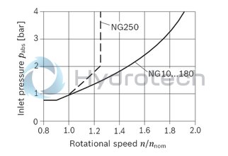
| 2) | Maximum speed (limiting speed) with increased inlet pressure pabs at suction port S, see the following diagram. |
| 3) | Torque without radial force, with radial force see table "Permissible radial and axial forces of the drive shafts" |
Maximum speed
Note
The values in the table are theoretical values, without consideration of efficiencies and tolerances. The values are rounded. Exceeding the maximum or falling below the minimum permissible values can lead to a loss of function, a reduction in operational service life or total destruction of the axial piston unit. Other permissible limit values, such as speed variation, reduced angular acceleration as a function of the frequency and the permissible angular acceleration at start (lower than the maximum angular acceleration) can be found in data sheet 90261.|
Determining the operating characteristics |
||
|
Flow |
 |
[l/min] |
|
Torque |
 |
[Nm] |
|
Power |
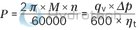 |
[kW] |
|
Key |
|
|
Vg |
Displacement per revolution [cm3] |
|
Δp |
Differential pressure [bar] |
|
n |
Rotational speed [rpm] |
|
ηv |
Volumetric efficiency |
|
ηhm |
Hydraulic-mechanical efficiency |
|
ηt |
Total efficiency (ηt = ηv • ηhm) |
Hydraulic fluids
The axial piston unit is designed for operation with mineral oil HLP according to DIN 51524.
Application instructions and requirements for hydraulic fluids should be taken from the following data sheets before the start of project planning:
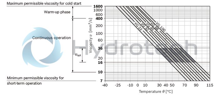
90220: Hydraulic fluids based on mineral oils and related hydrocarbons 90221: Environmentally acceptable hydraulic fluids 90222: Fire-resistant, water-free hydraulic fluids (HFDR, HFDU) 90223: Fire-resistan, water-containing hydraulic fluids (HFAE, HFAS, HFB, HFC) 90225: Restricted technical data for operation with fire-resistant hydraulic fluidsViscosity and temperature of hydraulic fluids
|
|
Viscosity |
Temperature1) |
Comment |
|
Cold start |
νmax ≤ 1600 mm²/s |
ϑSt ≥ -40 °C |
t ≤ 3 min, without load (p ≤ 50 bar), n ≤ 1000 rpm, |
|
Warm-up phase |
ν = 400 … 1600 mm²/s |
|
t ≤ 15 min, p ≤ 0.7 • pnom and n ≤ 0.5 • nnom |
|
Continuous operation |
ν = 10 … 400 mm²/s3) |
ϑ ≤ +103 °C |
measured at bleed port R |
|
νopt = 16 … 36 mm²/s |
range of optimum operating viscosity and efficiency |
||
|
Short-term operation |
νmin = 7 … 10 mm²/s |
ϑ ≤ +103 °C |
t ≤ 3 min, p ≤ 0.3 • pnom |
| 1) | If the specified temperatures cannot be maintained due to extreme operating parameters, please contact us. |
| 2) | Special version, please contact us. |
| 3) | Equates e.g. with the VG 46 a temperature range of +5 °C to +85 °C (see selection diagram) |
Explanatory note regarding the selection of hydraulic fluid
The hydraulic fluid should be selected such that the operating viscosity in the operating temperature range is within the optimum range (vopt see selection diagram).
Selection diagram
Filtration of the hydraulic fluid
Finer filtration improves the cleanliness level of the hydraulic fluid, which increases the service life of the axial piston unit.
A cleanliness level of at least 20/18/15 is to be maintained according to ISO 4406.
At a hydraulic fluid viscosity of less than 10 mm²/s (e.g. due to high temperatures in short-term operation) at the drain port, a cleanliness level of at least 19/17/14 according to ISO 4406 is required.
For example, the viscosity is 10 mm²/s at:
HLP 32 a temperature of 73°C HLP 46 a temperature of 85°COperating pressure range
|
Pressure at working port A or B (high-pressure side) |
Definition |
||
|
Nominal pressure |
pnom |
see table of values |
The nominal pressure corresponds to the maximum design pressure. |
|
Maximum pressure |
pmax |
see table of values |
The maximum pressure corresponds to the maximum operating pressure within the single operating period. The sum of the single operating periods must not exceed the total operating period. |
|
Single operating period |
10 s |
||
|
Total operating period |
300 h |
||
|
Minimum pressure |
pHP min |
25 bar |
Minimum pressure on high-pressure side (port A or B) required to prevent damage to the axial piston unit. |
|
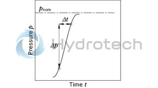
Rate of pressure change |
RA max |
16000 bar/s |
Maximum permissible rate of pressure build-up and reduction during a pressure change over the entire pressure range. |
|
Pressure at suction port S (inlet) |
Definition |
||
|
Minimum pressure |
ps min |
0.8 bar absolute |
Minimum pressure at inlet (suction port S) that is required to avoid damage to the axial piston unit. The minimum required pressure is dependent on the speed of the axial piston unit. |
|
Maximum pressure |
ps max |
30 bar absolute |
|
|
Case pressure at port T |
Definition |
||
|
Continuous differential pressure |
ΔpT cont |
2 bar |
Maximum averaged differential pressure at the shaft seal (case to ambient) |
|
Maximum differential pressure |
ΔpT max |
see diagram "Maximum differential pressure at the shaft seal" |
Intermittent differential pressure at the shaft seal (permitted at reduced speed) |
|
Pressure peaks |
pT peak |
10 bar |
t < 0.1 s |
Note
Working pressure range valid when using hydraulic fluids based on mineral oils. Values for other hydraulic fluids, please contact us.Pressure definition
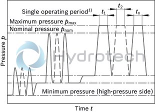
| 1) | Total operating period = t1 + t2 + ... + tn |
Rate of pressure change
Maximum differential pressure at the shaft seal
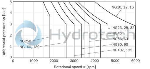
Note
The service life of the shaft seal is influenced by the speed of the axial piston unit and the case pressure. The service life decreases with an increase of the mean differential pressure between the case and the ambient pressure and with a higher frequency of pressure spikes. The case pressure must be equal to or higher than the ambient pressure.Direction of flow
|
Direction of rotation, viewed on drive shaft |
clockwise |
counter-clockwise |
|
Direction of flow |
S to B |
S to A |
Permissible radial and axial forces of the drive shaft
|
Size |
10 | 12 | 16 | 23 | 28 | 32 | 45 | 56 | 63 | 80 | 90 | 107 | 125 | 160 | 180 | 250 | ||||||||||||||||||||||||||||||||
|
Drive shaft |
Code |
S | P | B | S | P | B | S | B | S | P | B | S | P | B | S | B | S | P | S | T | P | B | S | T | B | Q | U | P | B | Q | U | B | U | S | P | B | U | S | B | S | P | B | S | B | S, P | ||
|
Maximum radial force |
 |
Fq max |
kN |
2.8 | 3 | 3.2 | 3.3 | 3 | 3.2 | 4.3 | 3.2 | 3.6 | 5.7 | 5.4 | 4.4 | 5.7 | 5.4 | 5.1 | 5.4 | 7.3 | 7.6 | 7.6 | 9.2 | 9.5 | 9.1 | 7.6 | 10.3 | 9.1 | 7.6 | 11.6 | 11.6 | 11.4 | 7.6 | 11.6 | 11.4 | 12.4 | 12.2 | 13.6 | 14.1 | 12.4 | 14.3 | 14.1 | 14.9 | 18.1 | 18.3 | 14.9 | 18.3 | 1.2 |
|
a |
mm |
16.8 | 16 | 16 | 16.8 | 16 | 16 | 16.8 | 16 | 24 | 16 | 16 | 24 | 16 | 16 | 24 | 16 | 24 | 18 | 24 | 24 | 18 | 18 | 24 | 24 | 18 | 24 | 24 | 20 | 20 | 24 | 24 | 20 | 27 | 33.5 | 20 | 20 | 27 | 33.5 | 20 | 33.5 | 25 | 25 | 33.5 | 25 | 41 | ||
|
Permitted torque at Fq max |
Tq max |
Nm |
66 | 66 | 66 | 76 | 76 | 76 | 98 | 102 | 146 | 146 | 146 | 179 | 179 | 179 | 204 | 204 | 290 | 290 | 302 | 357 | 357 | 357 | 302 | 401 | 401 | 302 | 450 | 512 | 512 | 302 | 450 | 573 | 594 | 679 | 679 | 679 | 594 | 796 | 796 | 828 | 1021 | 1021 | 828 | 1146 | ||
|
Permitted differential pressure at Fq max |
Δpq max |
bar |
400 | 400 | 400 | 400 | 400 | 400 | 385 | 400 | 400 | 400 | 400 | 400 | 400 | 400 | 400 | 400 | 400 | 400 | 339 | 400 | 400 | 400 | 301 | 400 | 400 | 237 | 352 | 400 | 400 | 211 | 314 | 400 | 349 | 400 | 400 | 400 | 298 | 400 | 400 | 325 | 400 | 400 | 289 | 400 | ||
|
Maximum axial force, when standstill or in non-pressurized conditions |
 |
+ Fax max |
N |
0 | 0 | 0 | 0 | 0 | 0 | 0 | 0 | 0 | 0 | 0 | 0 | 0 | 0 | 0 | 0 | 0 | 0 | 0 | 0 | 0 | 0 | 0 | 0 | 0 | 0 | 0 | 0 | 0 | 0 | 0 | 0 | 0 | 0 | 0 | 0 | 0 | 0 | 0 | 0 | 0 | 0 | 0 | 0 | 0 |
|
- Fax max |
N |
320 | 320 | 320 | 320 | 320 | 320 | 320 | 320 | 500 | 500 | 500 | 500 | 500 | 500 | 500 | 500 | 630 | 630 | 800 | 800 | 800 | 800 | 800 | 800 | 800 | 1000 | 1000 | 1000 | 1000 | 1000 | 1000 | 1000 | 1250 | 1250 | 1250 | 1250 | 1250 | 1250 | 1250 | 1600 | 1600 | 1600 | 1600 | 1600 | 2000 | ||
|
Maximum axial force, per bar operating pressure |
+ Fax max |
N/bar |
3 | 3 | 3 | 3 | 3 | 3 | 3 | 3 | 5.2 | 5.2 | 5.2 | 5.2 | 5.2 | 5.2 | 5.2 | 5.2 | 7 | 7 | 8.7 | 8.7 | 8.7 | 8.7 | 8.7 | 8.7 | 8.7 | 10.6 | 10.6 | 10.6 | 10.6 | 10.6 | 10.6 | 10.6 | 12.9 | 12.9 | 12.9 | 12.9 | 12.9 | 12.9 | 12.9 | 16.7 | 16.7 | 16.7 | 16.7 | 16.7 | ||
General information
The specified values are maximum data and not approved for continuous operation. The axial force in the direction of action -Fax is to be avoided as this reduces the bearing life cycle. The output by means of belts requires special conditions. Please consult us.Notes for size 250:
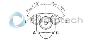
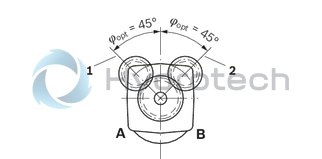
In case of radial forces limited performance data is valid. Please contact us. In case of axial forces during operation of the unit please contact us.Effect of radial force Fq on the service life of bearings
By selecting a suitable direction of radial force Fq the load on the bearings caused by the internal rotary group forces can be reduced, thus optimizing the service life of the bearings. Recommended position of mating gear is dependent on direction of rotation. Examples:
Toothed gear drive, size 10 … 180
Toothed gear drive, size 250
|
1 |
Direction of rotation "clockwise", pressure at port B |
|
2 |
Direction of rotation "counter-clockwise", pressure at port A |
Long-Life bearing
Size 250
For long service life and use with HF hydraulic fluids. Identical external dimensions as version with standard bearings. Subsequent conversion to long-life bearings is possible. Bearing and case flushing via port U is recommended.
Bearing flushing
Flushing flow (recommended)
|
Size |
250 | |
|
Flushing flow qv |
l/min |
10 |
Size 10 … 16
Drive shafts S, P and B
| 1) | Toothing data valid for basic number of teeth 48 |
| 2) | Thread according to ASME B1.1 |
| 3) | Center bore according to DIN 332 (thread according to DIN 13) |
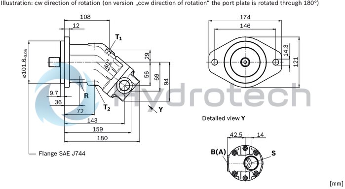
Ports
|
Size |
10 | 12 | 16 | ||
|
B (A) |
Working port |
Size |
1 1/16 in 12UN-2B; 20 mm deep | ||
|
Standard 1) |
ISO 11926 | ||||
|
State on delivery |
With protective cover (must be connected) | ||||
|
S |
Suction port |
Size |
1 5/16 in 12UN-2B; 20 mm deep | ||
|
Standard 1) |
ISO 11926 | ||||
|
State on delivery |
With protective cover (must be connected) | ||||
|
T1 |
Drain port |
Size |
9/16 in 18UNF-2B; 13 mm deep | ||
|
Standard 1) |
ISO 11926 | ||||
|
State on delivery 2) |
With protective cover (must be connected) | ||||
|
T2 |
Drain port |
Size |
9/16 in 18UNF-2B; 13 mm deep | ||
|
Standard 1) |
ISO 11926 | ||||
|
State on delivery 2) |
Plugged (observe installation instructions) | ||||
|
R |
Air bleed port |
Size |
5/16 in 24UNF-2B; 10 mm deep | ||
|
Standard 1) |
ISO 11926 | ||||
|
State on delivery |
Plugged | ||||
| 1) | The spot face can be deeper than specified in the appropriate standard. |
| 2) | Unless otherwise specified. Other layouts on request. |
Size 23 … 180
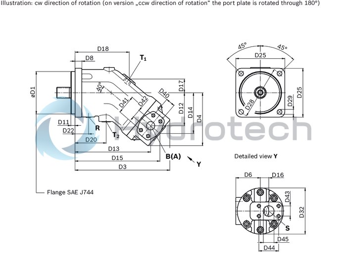
|
Size |
D1 |
D3 |
D4 |
D6 |
D8 |
D11 |
D12 |
D13 |
D14 |
D15 |
D16 |
D17 |
D18 |
D20 |
D22 |
D25 |
D28 |
D29 |
D32 |
D40 |
D41 |
D42 |
D43 |
D44 |
|
|
mm |
mm |
mm |
mm |
mm |
mm |
mm |
mm |
mm |
mm |
mm |
mm |
mm |
mm |
mm |
mm |
mm |
mm |
mm |
mm |
mm |
mm |
mm |
mm |
mm |
|
| 23 | 127 |
0 - 0.05 |
210 | 120 | 60 | 20 | 12.7 | 70 | 161 | 91 | 186 | 14 | 27 | 125 | 59 | 31 | 146 | 162 | 14.3 | 106 | 18.2 | 40.5 | 13 | 22.2 | 47.6 |
| 28 | 127 |
0 - 0.05 |
210 | 120 | 60 | 20 | 12.7 | 70 | 161 | 91 | 186 | 14 | 27 | 125 | 59 | 31 | 146 | 162 | 14.3 | 106 | 18.2 | 40.5 | 13 | 22.2 | 47.6 |
| 32 | 127 |
0 - 0.05 |
210 | 120 | 60 | 20 | 12.7 | 70 | 161 | 91 | 186 | 14 | 27 | 125 | 59 | 31 | 146 | 162 | 14.3 | 106 | 18.2 | 40.5 | 13 | 22.2 | 47.6 |
| 45 | 127 |
0 - 0.05 |
230 | 132 | 64 | 20 | 12.7 | 80 | 179 | 102 | 205 | 20 | 30 | 133 | 66 | 34 | 146 | 162 | 14.3 | 118 | 23.8 | 50.8 | 19 | 26.2 | 52.4 |
| 56 | 127 |
0 - 0.05 |
248 | 141 | 68 | 20 | 12.7 | 87 | 195 | 109 | 221 | 23 | 33 | 143 | 74 | 36 | 146 | 162 | 14.3 | 128 | 23.8 | 50.8 | 19 | 26.2 | 52.4 |
| 63 | 127 |
0 - 0.05 |
248 | 141 | 68 | 20 | 12.7 | 87 | 195 | 109 | 221 | 23 | 33 | 143 | 74 | 36 | 146 | 162 | 14.3 | 128 | 23.8 | 50.8 | 19 | 26.2 | 52.4 |
| 80 | 127 |
0 - 0.05 |
282 | 158 | 73 | 20 | 12.7 | 99 | 225 | 122 | 253 | 25 | 41 | 161 | 93 | 40 | 146 | 162 | 14.3 | 183 | 27.8 | 57.2 | 25 | 30.2 | 58.7 |
| 90 | 127 |
0 - 0.05 |
282 | 158 | 73 | 20 | 12.7 | 99 | 225 | 122 | 253 | 25 | 41 | 161 | 93 | 40 | 146 | 162 | 14.3 | 183 | 27.8 | 57.2 | 25 | 30.2 | 58.7 |
| 107 | 152.4 |
0 - 0.05 |
306 | 173 | 89 | 25 | 12.7 | 110 | 246 | 136 | 277 | 20 | 43 | 175 | 96.9 | 44 | 200 | 228.6 | 20.6 | 150 | 31.8 | 66.7 | 32 | 35.7 | 69.9 |
| 125 | 152.4 |
0 - 0.05 |
306 | 173 | 89 | 25 | 12.7 | 110 | 246 | 136 | 277 | 20 | 43 | 175 | 96.9 | 44 | 200 | 228.6 | 20.6 | 150 | 31.8 | 66.7 | 32 | 35.7 | 69.9 |
| 160 | 152.4 |
0 - 0.05 |
326 | 189 | 101 | 25 | 12.7 | 121 | 269 | 149 | 303 | 15 | 47 | 190 | 104 | 45 | 200 | 229 | 21 | 180 | 31.8 | 66.7 | 32 | 35.7 | 69.9 |
| 180 | 152.4 |
0 - 0.05 |
326 | 189 | 101 | 25 | 12.7 | 121 | 269 | 149 | 303 | 15 | 47 | 190 | 104 | 45 | 200 | 229 | 21 | 180 | 31.8 | 66.7 | 32 | 35.7 | 69.9 |
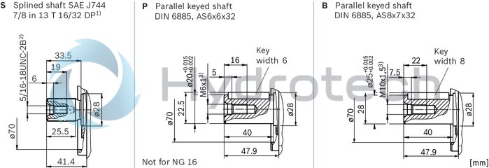
Drive shafts S and U
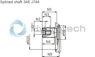
| 1) | Thread according to ASME B1.1 |
Splined shaft SAE J744
|
NG |
Code |
Designation 1) |
Thread G |
N2 |
N3 |
N4 |
N5 |
ØN6 |
N9 |
⌀N10 |
|
mm |
mm |
mm |
mm |
mm |
mm |
mm |
||||
| 23 | S | 1 1/4 in 14T 12/24 DP | 7/16-14UNC-2B | 9.5 | 28 | 40 | 48 | 35 | 55.9 | 80 |
| 28 | S | 1 1/4 in 14T 12/24 DP | 7/16-14UNC-2B | 9.5 | 28 | 40 | 48 | 35 | 55.9 | 80 |
| 32 | S | 1 1/4 in 14T 12/24 DP | 7/16-14UNC-2B | 9.5 | 28 | 40 | 35 | 35 | 55.9 | 80 |
| 45 | S | 1 1/4 in 14T 12/24 DP | 7/16-14UNC-2B | 9.5 | 28 | 40 | 48 | 35 | 55.9 | 95 |
| 56 | S | 1 1/4 in 14T 12/24 DP | 7/16-14UNC-2B | 9.5 | 28 | 40 | 48 | 40 | 55.9 | 105 |
| T | 1 3/8 in 21T 16/32 DP | 7/16-14UNC-2B | 9.5 | 28 | 40 | 48 | 40 | 55.9 | 105 | |
| 63 | S | 1 1/4 14T 12/24 DP | 7/16-14UNC-2B | 9.5 | 28 | 40 | 48 | 40 | 55.9 | 105 |
| T | 1 3/8 in 21T 16/32 DP | 7/16-14UNC-2B | 9.5 | 28 | 40 | 48 | 40 | 55.9 | 105 | |
| 80 | Q | 1 1/4 in 14T 12/24 DP | 7/16-14UNC-2B | 9.5 | 28 | 40 | 48 | 45 | 56 | 115 |
| U | 1 3/8 in 21T 16/32 DP | 7/16-14UNC-2B | 9.5 | 28 | 40 | 48 | 45 | 56 | 115 | |
| 90 | Q | 1 1/4 in 14T 12/24 DP | 7/16-14UNC-2B | 9.5 | 28 | 40 | 48 | 45 | 56 | 115 |
| U | 1 3/8 in 21T 16/32 DP | 7/16-14UNC-2B | 9.5 | 28 | 40 | 48 | 45 | 56 | 115 | |
| 107 | U | 1 1/2 in 23T 16/32 DP | 5/8-11UNC-2B | 12 | 36 | 56 | 62 | 50 | 69.9 | 125 |
| S | 1 3/4 in 13T 8/16 DP | 5/8-11UNC-2B | 12 | 36 | 55 | 67 | 50 | 74.9 | 125 | |
| 125 | U | 1 1/2 in 23T 16/32 DP | 5/8-11UNC-2B | 12 | 36 | 56 | 62 | 50 | 69.9 | 125 |
| S | 1 3/4 in 13T 8/16 DP | 5/8-11UNC-2B | 12 | 36 | 55 | 67 | 50 | 74.9 | 125 | |
| 160 | S | 1 3/4 in 13T 8/16 DP | 5/8-11UNC-2B | 12 | 36 | 55 | 67 | 60 | 74.9 | 140 |
| 180 | S | 1 3/4 in 13T 8/16 DP | 5/8-11UNC-2B | 12 | 36 | 55 | 67 | 60 | 74.9 | 140 |
| 1) | Toothing data valid for basic number of teeth 48 |
Drive shafts P and B
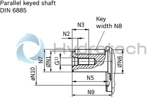
| 1) | Center bore according to DIN 332 (thread according to DIN 13) |
Parallel keyed shaft DIN 6885
|
NG |
Code |
Designation |
Thread G |
⌀N1 |
N2 |
N3 |
N5 |
⌀N6 |
N7 |
N8 |
N9 |
⌀N10 |
|
|
mm |
mm |
mm |
mm |
mm |
mm |
mm |
mm |
mm |
mm |
||||
| 23 | P | ⌀25, AS8x7x40 | M8 × 1.25 | 25 |
+ 0.015 + 0.002 |
6 | 19 | 50 | 35 | 28 | 8 | 57.9 | 80 |
| B | ⌀30, AS8x7x50 | M10 × 1.5 | 30 |
+ 0.015 + 0.002 |
7.5 | 22 | 50 | 35 | 33 | 8 | 57.9 | 80 | |
| 28 | P | ⌀25, AS8x7x40 | M8 × 1.25 | 25 |
+ 0.015 + 0.002 |
6 | 19 | 50 | 35 | 28 | 8 | 57.9 | 80 |
| B | ⌀30, AS8x7x50 | M10 × 1.5 | 30 |
+ 0.015 + 0.002 |
7.5 | 22 | 50 | 35 | 33 | 8 | 57.9 | 80 | |
| 32 | B | ⌀30, AS8x7x50 | M10 × 1.5 | 30 |
+ 0.015 + 0.002 |
7.5 | 22 | 50 | 35 | 33 | 8 | 57.9 | 80 |
| 45 | P | ⌀30, AS8x7x50 | M12 × 1.75 | 30 |
+ 0.015 + 0.002 |
9.5 | 28 | 60 | 35 | 33 | 8 | 67.9 | 95 |
| 56 | P | ⌀30, AS8x7x50 | M12 × 1.75 | 30 |
+ 0.015 + 0.002 |
9.5 | 28 | 60 | 40 | 33 | 8 | 67.9 | 105 |
| B | ⌀35, AS10x8x50 | M12 × 1.75 | 35 |
+ 0.018 + 0.002 |
9.5 | 28 | 60 | 40 | 38 | 10 | 67.9 | 105 | |
| 63 | B | ⌀35, AS10x8x50 | M12 × 1.75 | 35 |
+ 0.018 + 0.002 |
9.5 | 28 | 60 | 40 | 38 | 10 | 67.9 | 105 |
| 80 | P | ⌀35, AS10x8x56 | M12 × 1.75 | 35 |
+ 0.018 + 0.002 |
9.5 | 28 | 70 | 45 | 38 | 10 | 78 | 115 |
| B | ⌀40, AS12x8x56 | M16 × 2 | 40 |
+ 0.018 + 0.002 |
12 | 36 | 70 | 45 | 43 | 12 | 78 | 115 | |
| 90 | B | ⌀40, AS12x8x56 | M16 × 2 | 40 |
+ 0.018 + 0.002 |
12 | 36 | 70 | 45 | 43 | 12 | 78 | 115 |
| 107 | P | ⌀40, AS12x8x63 | M12 × 1.75 | 40 |
+ 0.018 + 0.002 |
9.5 | 28 | 80 | 50 | 43 | 12 | 87.9 | 125 |
| B | ⌀45, AS14x9x63 | M16 × 2 | 45 |
+ 0.018 + 0.002 |
12 | 36 | 80 | 50 | 48.5 | 14 | 87.9 | 125 | |
| 125 | B | ⌀45, AS14x9x63 | M16 × 2 | 45 |
+ 0.018 + 0.002 |
12 | 36 | 80 | 50 | 48.5 | 14 | 87.9 | 125 |
| 160 | P | ⌀45, AS14x9x70 | M16 × 2 | 45 |
+ 0.018 + 0.002 |
12 | 36 | 90 | 60 | 48.5 | 14 | 97.9 | 140 |
| B | ⌀50, AS14x9x70 | M16 × 2 | 50 |
+ 0.018 + 0.002 |
12 | 36 | 90 | 60 | 53.5 | 14 | 97.9 | 140 | |
| 180 | B | ⌀50, AS14x9x70 | M16 × 2 | 50 |
+ 0.018 + 0.002 |
12 | 36 | 90 | 60 | 53.5 | 14 | 97.9 | 140 |
Ports
|
Size |
23 | 28 | 32 | 45 | 56 | 63 | 80 | 90 | 107 | 125 | 160 | 180 | ||
|
B (A) |
Working port |
Size |
1/2 in | 3/4 in | 1 in | 1 1/4 in | ||||||||
|
Standard 1) |
Dimensions according to SAE J518 | |||||||||||||
|
Fastening thread |
5/16 in 18UNC-2B; 18 mm deep | 3/8 in 16UNC-2B; 21 mm deep | 3/8 in 16UNC-2B; 18 mm deep | 7/16 in 14UNC-2B; 22 mm deep | 1/2 in 13UNC-2B; 19 mm deep | |||||||||
|
State on delivery |
With protective cover (must be connected) | |||||||||||||
|
S |
Suction port |
Size |
3/4 in | 1 in | 1 1/4 in | 1 1/2 in | ||||||||
|
Standard |
Dimensions according to SAE J518 1) | |||||||||||||
|
Fastening thread |
3/8 in 16UNC-2B; 20 mm deep | 7/16 in 14UNC-2B; 26 mm deep | 7/16 in 14UNC-2B; 24 mm deep | 1/2 in 13UNC-2B; 24 mm deep | ||||||||||
|
State on delivery |
With protective cover (must be connected) | |||||||||||||
|
T1 |
Drain port |
Size |
3/4 in 16UNF-2B; 15 mm deep | 7/8 in 14UNF-2B; 17 mm deep | ||||||||||
|
Standard 1) |
ISO 11926 | |||||||||||||
|
State on delivery 2) |
With protective cover (observe installation instructions) | |||||||||||||
|
T2 |
Drain port |
Size |
3/4 in 16UNF-2B; 15 mm deep | 7/8 in 14UNF-2B; 17 mm deep | ||||||||||
|
Standard 1) |
ISO 11926 | |||||||||||||
|
State on delivery 2) |
Plugged (observe installation instructions) | |||||||||||||
|
R |
Air bleed port |
Size |
5/6 in 24UNF-2B; 10 mm deep | 7/16 in 24UNF-2B; 12 mm deep | 7/16 in 20UNF-2B; 12 mm deep | 9/16 in 20UNF-2B; 13 mm deep | ||||||||
|
Standard 1) |
ISO 11926 | |||||||||||||
|
State on delivery |
Plugged | |||||||||||||
| 1) | The spot face can be deeper than specified in the appropriate standard. |
| 2) | Unless otherwise specified. Other layouts on request. |
Size 250

Drive shafts S and K
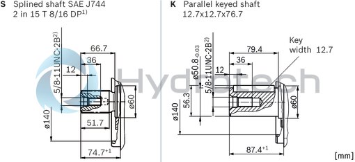
| 1) | Toothing data valid for basic number of teeth 48 |
| 2) | Thread according to ASME B1.1 |
Ports
|
Size |
250 | ||
|
B (A) |
Working port |
Size |
1 1/4 in |
|
Standard 1) |
Dimensions according to SAE J518 | ||
|
Fastening thread |
1/2 in 13UNC-2B; 20 mm deep | ||
|
State on delivery |
With protective cover (must be connected) | ||
|
S |
Suction port |
Size |
2 1/2 in |
|
Standard |
Dimensions according to SAE J518 1) | ||
|
Fastening thread |
1/2 in 13UNC-2B; 20 mm deep | ||
|
State on delivery |
With protective cover (must be connected) | ||
|
T1 |
Drain port |
Size |
7/8 in 14UNF-2B; 17 mm deep |
|
Standard 1) |
ISO 11926 | ||
|
State on delivery 2) |
With protective cover (observe installation instructions) | ||
|
T2 |
Drain port |
Size |
7/8 in 14UNF-2B; 17 mm deep |
|
Standard 1) |
ISO 11926 | ||
|
State on delivery 2) |
Plugged (observe installation instructions) | ||
|
U |
Bearing flushing |
Size |
9/16 in 20UNF-2B; 13 mm deep |
|
Standard 1) |
DIN 3852 | ||
|
State on delivery |
Plugged | ||
| 1) | The spot face can be deeper than specified in the appropriate standard. |
| 2) | Unless otherwise specified. Other layouts on request. |
Installation instructions
General
During commissioning and operation, the axial piston unit must be filled with hydraulic fluid and air bled. This must also be observed following a relatively long standstill as the axial piston unit may drain back to the reservoir via the hydraulic lines. Particularly in the installation position "drive shaft upwards" filling and air bleeding must be carried out completely as there is, for example, a danger of dry running. The case drain fluid in the housing must be directed to the reservoir via the highest available drain port (T1,T2). If a shared drain line is used for several units, make sure that the respective case pressure is not exceeded. The shared drain line must be dimensioned to ensure that the maximum permissible case pressure of all connected units is not exceeded in any operating conditions, specifically on cold start. If this is not possible, separate reservoir lines must be laid as required. To achieve favorable noise values, all connecting lines should be decoupled by using elastic elements and above-reservoir installation is to be avoided. In all operating conditions, the suction and drain lines must lead into the reservoir below the minimum fluid level. The permissible suction height hS results from the overall loss of pressure; it must not, however, be higher than hS max = 800 mm. The minimum suction pressure at port S must also not fall below 0,8 bar absolute during operation and during cold start. When designing the reservoir, ensure adequate space between the suction line and the drain line.This provides a slow-down and desgasification of the fluid and prevents that heated return flow is being drawn directly back into the suction line.Installation position
See the following examples 1 to 8.
Further installation positions are possible upon request. Recommended installation position: 1 and 2.
Below-tank installation (standard)
Below-tank installation is at hand if the axial piston unit is installed below the minimum liquid level outside the tank.
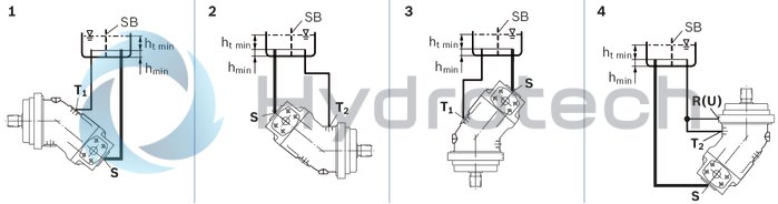
|
Installation position |
Air bleeding |
Filling |
|
1 |
‒ |
T1 |
|
2 |
‒ |
T2 |
|
3 |
‒ |
T1 |
|
4 |
R (U) |
T2 |
Above-reservoir installation
Above-reservoir installation means that the axial piston unit is installed above the minimum fluid level of the reservoir.
Recommendation for installation position 8 (drive shaft upward): A check valve in the drain line (cracking pressure 0,5 bar) can prevent draining of the pump housing.
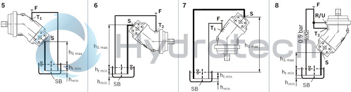
|
Installation position |
Air bleeding |
Filling |
|
5 |
F |
T1 (F) |
|
6 |
F |
T2 (F) |
|
7 |
F |
T1 (F) |
|
8 |
R (U) |
T2 (F) |
|
Key |
|
|
F |
Filling / Air bleeding |
|
R |
Air bleed port |
|
U |
Bearing flushing / air bleed port |
|
S |
Suction port |
|
T1, T2 |
Drain port |
|
ht min |
Minimum required immersion depth (200 mm) |
|
hmin |
Minimum required spacing to reservoir bottom (100 mm) |
|
SB |
Baffle (baffle plate) |
|
hS max |
Maximum permissible suction height (800 mm) |
| Note: Connection F is part of the external piping and must be provided on the customer side to simplify the filling and bleeding. |
Note
Connection F is part of the external piping and must be provided on the customer side to simplify the filling and bleeding.General project planning notes
The axial piston unit is designed to be used in open circuits. The project planning, installation and commissioning of the axial piston unit require the involvement of qualified skilled personnel. Before using the axial piston unit, please read the corresponding instruction manual completely and thoroughly. If necessary, request it from Bosch Rexroth. Before finalizing your design, request a binding installation drawing. The specified datas and notes must be observed. Preservation: Our axial piston units are supplied as standard with preservative protection for a maximum of 12 months. If longer preservative protection is required (maximum 24 months), please specify this in plain text when placing your order. The preservation times are valid under optimal storage conditions. Details of these conditions can be found in the data sheet 90312 or the instruction manual. A pressure relief valve is to be provided in the hydraulic system. Observe the instructions in the instruction manual regarding tightening torques of connection threads and other threaded joints used. The notes in the instruction manual on tightening torques of the port threads and other screw joints must be observed. The ports and fastening threads are designed for the permissible maximum pressure pmax (see instruction manual). The machine or system manufacturer must ensure that the connecting elements and lines correspond to the specified operating conditions (pressure, flow, hydraulic fluid, temperature) with the necessary safety factors. The working ports and function ports are designated only to accommodate hydraulic lines.During and shortly after operation, there is a risk of burns on the axial piston unit. Take appropriate safety measures (e.g. by wearing protective clothing).