
BOSCH REXROTH
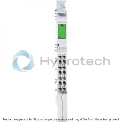
R-IBILAI2/SF-PAC
R911170784
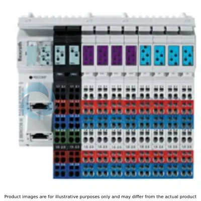
I/O Rexroth Inline Analogue modules
BOSCH REXROTH
MATERIAL: R911170784
SUMMARY: I/O Rexroth Inline Analogue modules
Quantity in stock: 2
Quantity Details:- Hydrotech Stock: 0 can ship April 22, 2024
- Factory Stock: 2 can ship June 10, 2024
This module is designed for use within an Inline station. It is used to acquire analog voltage or current signals.
General data
|
Type |
R-IB IL AI 2/SF-PAC | |
|
Weight 1) |
g |
69 |
|
Operating mode |
Process data mode with 2 words | |
|
Sensor connection type |
2-, 3-wire technology | |
|
Sensor supply voltage |
Via external power supply unit or via additional segment module with fuse R-IB IL 24 SEG/F | |
|
Ambient temperature (operation) |
-25 °C ... +55 °C | |
|
Ambient temperature (storage/transport) |
-25 °C ... +85 °C | |
|
Permissible relative humidity (operation) |
10 % ... 95 % acc. to DIN EN 61131-2 | |
|
Permissible relative humidity (storage/transport) |
10 % ... 95 % acc. to DIN EN 61131-2 | |
|
Air pressure (operation) |
70 kPa ... 106 kPa (up to 3000 m above sea level) | |
|
Air pressure (storage/transport) |
70 kPa ... 106 kPa (up to 3000 m above sea level) | |
|
Protection type |
IP20, IEC 60529 | |
|
Protection class |
III, IEC 61140 | |
| 1) | Including plug |
Connection data
|
Type |
R-IB IL AI 2/SF-PAC | |
|
Designation |
Inline connection plug | |
|
Connection type |
Tension spring modules | |
|
Conductor cross-section solid/flexible/AWG |
0.2 mm² ... 1.5 mm² 0.2 mm² ... 1.5 mm² 24 ... 16 |
|
Interface local bus
|
Type |
R-IB IL AI 2/SF-PAC | |
|
Connection type |
Data ranking | |
|
Transmission speed |
kBit/s |
500 |
Inline potentials/performance balance
|
Type |
R-IB IL AI 2/SF-PAC | |
|
Logic voltage UL |
V DC |
7.5 |
|
Typical current consumption from UL |
mA |
45 |
|
Maximum current consumption from UL |
mA |
60 |
|
Peripheral supply voltage UANA |
V DC |
24 |
|
Typical current consumption from UANA |
mA |
13 |
|
Maximum current consumption from UANA |
mA |
18 |
|
Typical power consumption total |
mW |
662 |
|
Maximum power consumption total |
mW |
882 |
Supply of module electronics and peripherals via bus coupler/power feed module
|
Type |
R-IB IL AI 2/SF-PAC | |
|
Connectivity technology |
Potential jumpers | |
Analog inputs
|
Type |
R-IB IL AI 2/SF-PAC | |
|
Number of analog inputs 1) |
2 | |
|
A/D conversion time |
µs |
120 |
|
Measurement representation |
16 bits (15 bits + sign) 13 bits (12 bits + sign) 16 bits (15 bits + sign) 16 bits (15 bits + sign) - - |
|
|
Data formats |
IB IL, IB ST, IB RT, standardized representation | |
|
Average |
Over 16 measured values (deactivatable) | |
|
Overvoltage protection |
Suppressor diodes in the analog inputs | |
| 1) | Analog single-ended inputs |
Analog input levels
|
Type |
R-IB IL AI 2/SF-PAC | |
|
Voltage inputs |
||
|
Input resistance |
kΩ |
> 220 |
|
Limit frequency (3 dB) |
Hz |
40 |
|
Internal process data update for both channels |
ms |
< 1.5 |
|
Behavior upon sensor interruption |
Goes to 0 V | |
|
Maximum permissible voltage between analog voltage inputs and analog reference potential |
V |
± 32 |
|
Common mode rejection (CMR) |
Min. 90 dB - |
|
|
Reference: Voltage input signal, valid for permitted DC common mode voltage range |
dB |
110 |
|
Permitted DC common mode voltage for CMR 1) |
V |
40 |
|
Current inputs |
||
|
Input resistance 2) |
Ω |
50 |
|
Limit frequency (3 dB) |
Hz |
40 |
|
Internal process data update for both channels |
ms |
< 1.5 |
|
Behavior upon sensor interruption |
Regulating toward 0 mA or 4 mA | |
|
Maximum permissible voltage between analog current inputs and analog reference potential 3) |
V |
± 5 |
|
Common mode rejection (CMR) |
Min. 90 dB | |
|
Reference: Power input signal, valid for permitted DC common mode voltage range |
dB |
110 |
|
Permitted DC common mode voltage for CMR 4) |
V |
40 |
|
Maximum permitted power |
mA |
± 100 |
| 1) | Between voltage input and FE |
| 2) | Measuring resistance |
| 3) | Equal to 100 mA over the sensing resistances |
| 4) | Between current input and FE |
Mechanical tests
|
Type |
R-IB IL AI 2/SF-PAC | |
|
Shock 1) |
Load 15 g for 11 ms, half sinusoidal wave, three shocks per spatial direction and orientationLoad 25 g for 6 ms, half sinusoidal wave, three shocks per spatial direction and orientation acc. to EN 60068-2-27/IEC 60068-2-27 | |
| 1) | Deviations compared to the common technical data given in the application description DOK-CONTRL-ILSYSPRO***-AW..-DE-P |
Conformity
|
Type |
R-IB IL AI 2/SF-PAC | ||
|
Conforms with |
|||
|
Testing of interference immunity acc. to EN 61000-6-2 1) |
Discharge of static electricity (ESD) |
Criterion B; 6 kV contact discharge; 6 kV air discharge acc. to EN 61000-4-2/IEC 61000-4-2 | |
| 1) | Deviations compared to the common technical data given in the application description DOK-CONTRL-ILSYSPRO***-AW..-DE-P |
Tolerance and temperature behavior for the voltage inputs
| Typical | Maximum | ||
|
The tolerance specifications refer to the measurement range end value of 10 V |
|||
|
Tolerance at 23 °C |
|||
|
Tolerance via offset |
% |
± 0.03 | ± 0.06 |
|
Tolerance via gain |
% |
± 0.05 | ± 0.1 |
|
Differential non-linearity |
% |
± 0.1 | ± 0.2 |
|
Total tolerance of voltage inputs at 23 ° C Tolerance via offset, gain, and linearity |
% |
± 0.15 | ± 0.3 |
|
Temperature behavior from -25 °C to +55 °C |
|||
|
Offset drift TKVO |
ppm/K |
± 6 | ± 12 |
|
Gain drift TKG |
ppm/K |
± 30 | ± 50 |
|
Total voltage drift TKges = TKVO + TKG |
ppm/K |
± 36 | ± 62 |
|
Total tolerance of voltage inputs for -25 °C to +55 °C Tolerance via offset, gain, linearity and drift |
% |
± 0.3 | ± 0.5 |
Tolerance and temperature behavior of the power inputs
| Typical | Maximum | ||
|
The tolerance specifications refer to the measurement range end value of 20 mA |
|||
|
Tolerance at 23 °C |
|||
|
Tolerance via offset |
% |
± 0.03 | ± 0.06 |
|
Tolerance via gain |
% |
± 0.1 | ± 0.1 |
|
Differential non-linearity |
% |
± 0.1 | ± 0.3 |
|
Total tolerance of current inputs at 23 °C Tolerance via offset, gain, and linearity |
% |
± 0.2 | ± 0.4 |
|
Temperature behavior from -25 °C to +55 °C |
|||
|
Offset drift TKIO |
ppm/K |
± 6 | ± 12 |
|
Gain drift TKG |
ppm/K |
± 30 | ± 50 |
|
Total voltage drift TKges = TKIO + TKG |
ppm/K |
± 36 | ± 62 |
|
Total tolerance of current inputs for -25 °C to +55 °C Tolerance via offset, gain, linearity and drift |
% |
± 0.35 | ± 0.6 |
Additional tolerances under the influence of electromagnetic fields
|
Type |
R-IB IL AI 2/SF-PAC | |||
|
Type of electromagnetic interference |
Typical deviation from the measurement range end value |
|||
|
Electro-magnetic fields Field strength 10 V/macc. to EN 61000-4-3/IEC 61000-4-3 |
Voltage input |
Relative |
% |
< ± 2 |
|
Absolute |
mV |
< ± 200 | ||
|
Current input |
Relative |
% |
< ± 2 | |
|
Absolute |
μA |
< ± 400 | ||
|
Line-fed disturbances III (test voltage 10 V)acc. to EN 61000-4-6/IEC 61000-4-6 |
Voltage input |
Relative |
% |
< ± 1 |
|
Absolute |
mV |
< ± 100 | ||
|
Current input |
Relative |
% |
< ± 1 | |
|
Absolute |
μA |
< ± 100 | ||
|
Fast transient disturbances (burst) supply 4 kV, input 2 kVacc. to EN 61000-4-4/IEC 61000-4-4 |
Voltage input |
Relative |
% |
< ± 1 |
|
Absolute |
mV |
< ± 100 | ||
|
Current input |
Relative |
% |
< ± 1 | |
|
Absolute |
μA |
< ± 100 | ||
|
Approvals |
|
The current approvals can be found at www.boschrexroth.com. |
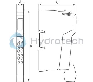
Dimensions
|
Type |
R-IB IL AI 2/SF-PAC | |
|
A |
mm |
12.2 |
|
B |
mm |
136.8 |
|
C |
mm |
71.5 |
|
Note on dimensions |
The depth applies when using a support rail TH 35-7.5 (acc. to EN 60715). | |