
BOSCH REXROTH
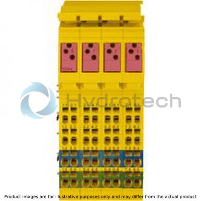
R-IBIL24PSDO4/4-PAC
R911172849
All Other Products
I/O Rexroth Inline Digital: SIL3 Input
BOSCH REXROTH
MATERIAL: R911172849
SUMMARY: I/O Rexroth Inline Digital: SIL3 Input
Quantity in stock: 2
Quantity Details:- Hydrotech Stock: 0 can ship April 26, 2024
- Factory Stock: 2 can ship June 14, 2024
The R-IB IL 24 PSDO 4/4-PAC module is an output module that is assigned for use within an Inline station.
General data
|
Type |
R-IB IL 24 PSDO 4/4-PAC | |
|
Weight 1) |
g |
200 |
|
Operating mode |
PROFIsafe process data mode with 4 words and 1 word PCP (internal use) | |
|
Ambient temperature (operation) |
-25 °C ... +55 °C | |
|
Ambient temperature (storage/transport) |
-25 °C ... +70 °C | |
|
Permissible relative humidity (operation) |
75% on average, 85% occasionally (no condensation) | |
|
Permissible relative humidity (storage/transport) |
75% on average, 85% occasionally (no condensation) | |
|
Air pressure (operation) |
80 kPa … 108 kPa (up to 2000 m above sea level) | |
|
Air pressure (storage/transport) |
66 kPa … 108 kPa (up to 3500 m above sea level) | |
|
Protection type |
IP20 | |
|
Protection class |
III, IEC EN 61140, VDE 0140-1 | |
|
Clearances and creepage distances |
Acc. to IEC 60439-1, derived from IEC 60664-1 | |
|
Housing material |
Plastic PBT, self-extinguishing (V0) | |
|
Supported stop category |
0; 1 in error-free state acc. to EN 60204 | |
| 1) | Including plug |
Connection data
|
Type |
R-IB IL 24 PSDO 4/4-PAC | |
|
Designation |
Inline connection plug | |
|
Connection type |
Tension spring modules | |
|
Conductor cross-section solid/flexible/AWG |
0.2 mm² ... 1.5 mm² 0.2 mm² ... 1.5 mm² 24 ... 16 |
|
Interface local bus
|
Type |
R-IB IL 24 PSDO 4/4-PAC | |
|
Transmission speed |
kBaud MBaud |
500 2 |
Safety characteristics
|
Type |
R-IB IL 24 PSDO 4/4-PAC | |
|
Acc. to IEC 61508/EN 61508 |
||
|
Achievable SIL 1) |
SIL 2 (single-channel) SIL 3 (two-channel) - |
|
|
Probability of dangerous failure by demand through the safety function (PFD) |
SIL 2: Maximum 1 % of 10-2 (corresponds to 1 * 10-4) SIL 3: Maximum 1 % of 10-3 (corresponds to 1 * 10-5) |
|
|
Probability of dangerous failure per hour for the whole module (PFH) 2) |
SIL 2: Maximum 1 % of 10-6 (corresponds to 1 * 10-8) SIL 3: Maximum 1 % of 10-7 (corresponds to 1 * 10-9) - |
|
|
Hardware error tolerance (HFT) of the module |
1 | |
|
Permissible operating time |
Years |
20 |
|
Acc. to EN 62061 |
||
|
Achievable SIL Claim Limit 1) |
SIL CL 2 = SIL 2 (single-channel) SIL CL 3 = SIL 3 (two-channel) - |
|
|
Safe Failure Fraction (SFF) |
% |
99 |
|
Probability of dangerous failure per hour for the whole module (PFH) 2) |
SIL CL 2: Maximum 1 % of 10-6 (corresponds to 1 * 10-8) SIL CL 3: Maximum 1 % of 10-7 (corresponds to 1 * 10-9) - |
|
|
Hardware error tolerance (HFT) of the module |
1 | |
|
Permissible operating time |
Years |
20 |
|
Acc. to EN ISO 13849-1 |
||
|
Achievable Performance Level 1) |
PL e (two-channel) PL d (single-channel) - |
|
|
Degree of diagnostic cover (DC) |
% |
99 |
|
Mean time to a dangerous failure (MTTFd) |
For single-channel occupancy: 100 years For two-channel occupancy: 100 years |
|
| 1) | Depending on the parameterization and circuit |
| 2) | Depending on the parameterization |
Supply voltage UL
|
Type |
R-IB IL 24 PSDO 4/4-PAC | |
|
Maximum current consumption |
mA |
≤ 230 |
Supply voltage UM
|
Type |
R-IB IL 24 PSDO 4/4-PAC | |
|
Nominal voltage 1) |
V DC |
24 |
|
Tolerance |
-15 %/+20 % including an overall alternating current component with peak value 5 % | |
|
Ripple |
Vpp |
3.6 |
|
Permissible voltage range 2) |
19.2 V DC ... 30 V DC | |
|
Typical current consumption 3) |
mA |
30 |
|
Permitted interruption time 4) |
ms |
10 |
|
Overvoltage protection |
Protection elements of the bus coupler or the feed module | |
|
Reverse polarity protection |
Protection elements of the bus coupler or the feed module | |
|
Undervoltage detection |
V |
≈ 17 |
|
Diagnosis displays |
LED (green) UM | |
|
External protection 5) |
A |
≤ 8 |
| 1) | Acc. to EN 61131-2, EN 60204 |
| 2) | Including ripple |
| 3) | All outputs set, plus the current to the actuators |
| 4) | Within this period of time, the output voltage for the secure outputs breaks down, since the outputs are not buffered internally |
| 5) | Slow time-lag |
Safe digital outputs
|
Type |
R-IB IL 24 PSDO 4/4-PAC | ||
|
Number of digital outputs |
4/4 (two-channel/single-channel, plus-switching) | ||
|
Number of digital outputs |
Switching to plus |
4 (OUT0_Ch1, OUT1_Ch1, OUT2_Ch1, OUT3_Ch1) | |
|
Switching to minus 1) |
4 (OUT0_Ch2, OUT1_Ch2, OUT2_Ch2, OUT3_Ch2) | ||
|
Supply |
From UM | ||
|
Maximum output current |
Per output |
A |
≤ 2 |
|
All outputs (total current) |
A |
≤ 3 | |
|
Maximum output voltage low state |
V |
< 5 | |
|
Maximum leakage current low state |
mA |
2 | |
|
Minimum holding voltage of the connected loads |
V |
> 5 | |
|
Maximum load |
Inductance |
H |
1 |
|
Capacitive (in relation to current) |
C = 1 s/(R • 1400) Where: C Load capacity in F R Load resistance in Ohm |
||
|
Minimum load |
16 mA at 24 V |
kΩ |
1.5 |
|
Limited inductive cut-off voltage |
V |
- 15 | |
|
Output voltage |
UM ‒ 1 V | ||
|
Simultaneity 2) |
% |
100 | |
|
Maximum switching frequency |
1 Hz; 0.2 Hz > 1 A - - |
||
|
Switch-off delay for shutdown 3) |
Configurable |
150 ms ... 630 s | |
|
Maximum duration of test pulses |
In deactivated state; drive actively |
ms |
1 |
|
In activated state 4) |
ms |
3 | |
|
Status indicators |
One green LED per output (two-color LED green/red) | ||
|
Diagnosis displays |
One red LED per output (two-color LED green/red) | ||
| 1) | Only operating together with the associated plus switching outputs OUTx_Ch1 |
| 2) | Observe maximum current load |
| 3) | After stop category 1; precision ±5 % of parameterized value |
| 4) | Depending on the load capacity |
Electrical isolation/insulation of the voltage ranges
|
Type |
R-IB IL 24 PSDO 4/4-PAC | |
|
Common potentials |
||
|
For the potential separation of the logic layer from the peripheral area, it is necessary to use separate power supplies when supplying the station's bus coupler and the safety module described here. A connection to the supply devices in the 24 V range is not allowed! (See also application description.) |
||
|
Separate potentials in the system of bus coupler/feed module and safety module |
||
|
Test distance |
Test voltage | |
|
5 V supply incoming remote bus/7.5 V supply (bus logic) |
500 V AC, 50 Hz, 1 min. | |
|
5 V supply to further remote bus/7.5 V supply (bus logic) |
500 V AC, 50 Hz, 1 min. | |
|
7.5 V power supply (bus logic)/24 V power supply UM, FE |
500 V AC, 50 Hz, 1 min. | |
Mechanical tests
|
Type |
R-IB IL 24 PSDO 4/4-PAC | |
|
Vibration resistance 1) |
Operation: 2 g; criterion A | |
|
Shock 2) |
15 g, 11 ms; criterion A | |
| 1) | Acc. to IEC 60068-2-6 |
| 2) | Acc. to IEC 60068-2-27 |
Conformity
|
Type |
R-IB IL 24 PSDO 4/4-PAC | ||
|
Conforms with |
|||
|
Testing of interference immunity acc. to EN 61000-6-2 |
Discharge of static electricity (ESD) |
Criterion B; 6 kV contact discharge; 8 kV air discharge acc. to EN 61000-4-2/IEC 61000-4-2 | |
|
Electro-magnetic fields |
Criterion A; field strength: 10 V/m acc. to EN 61000-4-3/IEC 61000-4-3 | ||
|
Fast transients (burst) |
Criterion B; test voltage 2 kV acc. to EN 61000-4-4/IEC 61000-4-4 | ||
|
Transient overvoltage (surge) |
Testing severity 2, criterion B;supply lines DC: ±0.5 kV/±0.5 kV (symmetric/asymmetric); signal lines: ±1 kV/±2 kV (symmetric/asymmetric) acc. to EN 61000-4-5/IEC 61000-4-5 | ||
|
Line-fed disturbances (ODS) |
Criterion A; test voltage 10 V acc. to EN 61000-4-6/IEC 61000-4-6 | ||
|
Testing of disturbance transmission acc. to EN 61000-6-4 |
Testing of line-fed disturbance transmission |
Class A, industrial area acc. to EN 55011 | |
|
Approvals |
|
The current approvals can be found at www.boschrexroth.com. |
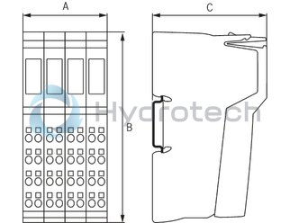
Dimensions
|
Type |
R-IB IL 24 PSDO 4/4-PAC | |
|
A |
mm |
48.8 |
|
B |
mm |
120 |
|
C |
mm |
71.5 |
|
Note on dimensions |
The depth applies when using a support rail TH 35-7.5 (acc. to EN 60715). | |