
BOSCH REXROTH
H-4WMM16C7X/V
R978902114
Directional Spool Valves
Directional spool valves: WMM 16.-7x/
BOSCH REXROTH
MATERIAL: R978902114
SUMMARY: Directional spool valves: WMM 16.-7x/
Quantity in stock: 0
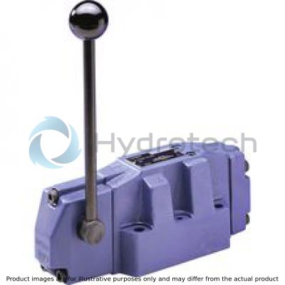
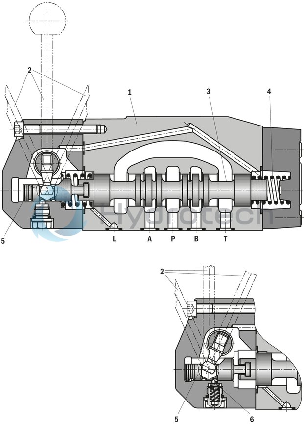
Valves type WMM are manually actuated directional spool valves. They control the start, stop and direction of a flow and basically consist of housing (1), hand lever (2), control spool (3) and one or two return springs (4).
When de-energized, the control spool (3) is held in the central position or in the initial position by the return springs (4). The control spool (3) is actuated directly by the hand lever (2). By means of a socket and the bolt (5), it acts directly on the control spool (3) which is thereby moved from its rest position to the desired end position.
When the hand lever (2) has been reset to spool position zero, the return spring (4) pushes the control spool (3) back to its rest position again.
Type H-4WMM../F.. (with detent)
This version is a directional valve with 2 or 3 spool positions and a detent (6) which locks all spool positions.
Type H-4WMM 16 E 7X/…
Type H-4WMM 16 E 7X/F… (with detent)
|
01 |
02 |
03 |
04 |
05 |
06 |
07 |
08 |
09 |
10 |
||
|
H |
– |
4 |
WMM |
/ |
* |
|
01 |
Maximum operating pressure 350 bar |
H |
|
02 |
4 main ports |
4 |
|
Actuation |
||
|
03 |
Hand lever |
WMM |
|
04 |
Size 16 |
16 |
|
Size 25 |
22 |
|
|
Size 32 |
32 |
|
|
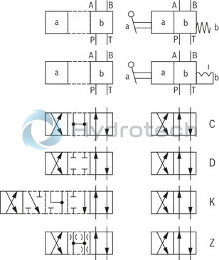
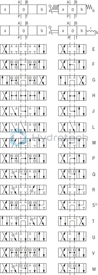
05 |
Spool symbol, e. g. C, E etc., see Symbols |
|
|
06 |
NG16 and 25 – Component series 70 to 79 (70 to 79: unchanged installation and connection dimensions) |
7X |
|
NG32 – Component series 30 to 39 (30 to 39: unchanged installation and connection dimensions) |
5X |
|
|
07 |
With spring return |
no code |
|
With detent |
F |
|
|
Spool position monitoring (NG16 and 25 only) |
||
|
08 |
Without position switch |
no code |
|
Monitored spool position "a" |
QMAG24 |
|
|
Monitored spool position "b" |
QMBG24 |
|
|
Monitored rest position |
QM0G24 |
|
|
Seal material |
||
|
09 |
NBR seals |
no code |
|
FKM seals (other seals upon request) Observe compatibility of seals with hydraulic fluid used. |
V |
|
|
10 |
Further details in the plain text |
* |
Preferred types and standard units are contained in the EPS (standard price list).
general
|
Size |
16 | 25 | 32 | ||
|
Weight (approx.) |
kg |
8 | 12.2 | 49 | |
|
Operating force |
with detent (approx.) |
N |
75 | 105 | 100 |
|
with spring return (max.) |
N |
75 | 105 | 150 | |
|
Installation position |
any | ||||
|
Ambient temperature range |
NBR seals |
°C |
-30 … +80 | ||
|
FKM seals |
°C |
-20 … +80 | |||
|
Actuation angle from the central position 1) |
2 x |
° |
26 | 24.5 | 25 |
| 1) | see Unit dimensions |
hydraulic
|
Size |
16 | 25 | 32 | ||
|
Maximum operating pressure |
Port A |
bar |
350 | ||
|
Port B |
bar |
350 | |||
|
Port P |
bar |
350 | |||
|
Port T |
bar |
250 1) | 250 2) | ||
|
Maximum flow |
l/min |
300 | 450 | 1100 | |
|
Hydraulic fluid |
see table | ||||
|
Hydraulic fluid temperature range |
NBR seals |
°C |
-30 … +80 | ||
|
FKM seals |
°C |
-20 … +80 | |||
|
Viscosity range |
mm²/s |
2.8 … 380 | |||
|
Maximum admissible degree of contamination of the hydraulic fluid 3) |
Class 20/18/15 according to ISO 4406 (c) | ||||
|
Flow cross-section |
Symbol Q (A/B → T) |
mm² |
32 | 78 | 116 |
|
Symbol V (A/B → T) |
mm² |
32 | 73 | 136 | |
|
Symbol V (P → A/B) |
mm² |
32 | 84 | 120 | |
|
Symbol W (A/B → T) |
mm² |
6 | 10 | 20 | |
| 1) | With a tank pressure > 160bar, the leakage oil has to be discharged via port L! |
| 2) | With a tank pressure > 160 bar, the leakage oil has to be discharged via port Y! |
| 3) | The cleanliness classes specified for the components must be adhered to in hydraulic systems. Effective filtration prevents faults and simultaneously increases the life cycle of the components. For the selection of the filters, see www.boschrexroth.com/filter. |
|
Hydraulic fluid |
Classification |
Suitable sealing materials |
Standards |
|
|
Mineral oil |
HL, HLP |
FKM, NBR |
DIN 51524 |
|
|
Bio-degradable |
Insoluble in water |
HEES (synthetic esters) |
FKM |
VDMA 24568 |
|
HETG (rape seed oil) |
FKM, NBR |
|||
|
Soluble in water |
HEPG (polyglycols) |
FKM |
VDMA 24568 |
|
|
Other hydraulic fluids on request |
||||
Inductive position switch type QM: electrical connection
The electric connection is realized via a 4-pole mating connector (separate order) with connection thread M12 x 1.
electrical
|
Connection voltage (DC voltage) |
V |
24 | ||
|
Voltage tolerance (connection voltage) |
+30 %/-15 % | |||
|
Admissible residual ripple |
% |
≤ 10 | ||
|
Max. load capacity |
mA |
400 | ||
|
Switching outputs 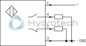 |
PNP transistor outputs, load between switching outputs and GND | |||
|
Pinout  |
1 |
V |
24 | |
|
2, 4 |
Switching output |
mA |
400 | |
|
3 |
Earthing (GND) |
V |
0 | |
For applications outside these parameters, please consult us!
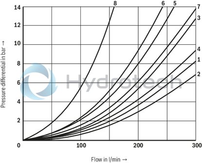
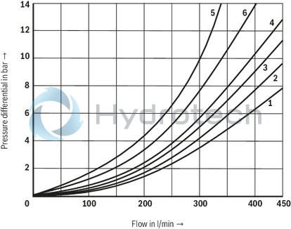
(measured with HLP46, ϑOil = 40 ±5 °C)
Δp-qV characteristic curves
Size 16
|
Symbol |
Direction of flow |
||||
|
P – A |
P – B |
A – T |
B – T |
P – T |
|
|
E, D, Y |
1 |
1 |
1 |
3 |
– |
|
F |
2 |
2 |
3 |
3 |
– |
|
G, T |
5 |
1 |
3 |
7 |
6 |
|
H, C, Q |
2 |
2 |
3 |
3 |
– |
|
V, Z |
2 |
2 |
3 |
3 |
– |
|
J, K, L |
1 |
1 |
3 |
3 |
– |
|
M, W |
2 |
2 |
4 |
3 |
– |
|
R |
2 |
2 |
4 |
– |
– |
|
U |
1 |
1 |
4 |
7 |
– |
|
S |
4 |
4 |
4 |
– |
8 |
Performance limits
(measured with HLP46, ϑOil = 40 ±5 °C)
Attention!
The switching function of the valves is independent from the filtration due to the adhesive effect. To achieve the specified admissible flows, a full flow filtration with 25 μm is recommended. The flow forces acting within the valves also influence the flow performance.
With 4-way directional valves, the specified flows are therefore valid for normal operation with 2 directions of flow (e. g. from P to A and simultaneous return flow from B to T). If there is only one direction of flow, the admissible flow may be significantly lower (e. g. if a 4-way directional valve is used as a 3-way directional valve due to blocked port A or B).
NG16
|
2-spool position valve – qV max |
|||||
|
Symbol |
Operating pressure pmax in bar |
||||
|
70 bar |
140 bar |
210 bar |
280 bar |
350 bar |
|
|
With spring return |
|||||
|
C |
300 l/min |
300 l/min |
300 l/min |
260 l/min |
220 l/min |
|
D |
300 l/min |
300 l/min |
210 l/min |
190 l/min |
160 l/min |
|
K |
300 l/min |
300 l/min |
200 l/min |
150 l/min |
130 l/min |
|
Z |
300 l/min |
240 l/min |
190 l/min |
170 l/min |
150 l/min |
|
With detent |
|||||
|
C, D, K, Z |
300 l/min |
300 l/min |
300 l/min |
300 l/min |
300 l/min |
NG16
|
3-spool position valve – qV max |
|||||
|
Symbol |
Operating pressure pmax in bar |
||||
|
70 bar |
140 bar |
210 bar |
280 bar |
350 bar |
|
|
With spring return |
|||||
|
E, H, J, L, M, Q, R, U, W |
300 l/min |
300 l/min |
300 l/min |
300 l/min |
300 l/min |
|
F, P |
300 l/min |
300 l/min |
210 l/min |
190 l/min |
170 l/min |
|
G, S, T |
300 l/min |
300 l/min |
220 l/min |
210 l/min |
180 l/min |
|
V |
300 l/min |
260 l/min |
200 l/min |
180 l/min |
170 l/min |
|
With detent |
|||||
|
E, H, J, L, M, Q, R, U, W |
300 l/min |
300 l/min |
300 l/min |
300 l/min |
300 l/min |
|
F, P |
300 l/min |
300 l/min |
280 l/min |
230 l/min |
230 l/min |
|
G, S, T |
300 l/min |
300 l/min |
230 l/min |
230 l/min |
230 l/min |
|
V |
300 l/min |
300 l/min |
250 l/min |
230 l/min |
230 l/min |
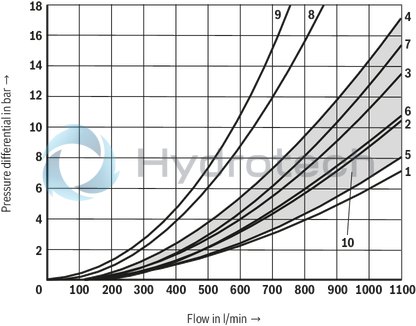
(measured with HLP46, ϑOil = 40 ±5 °C)
Δp-qV characteristic curves
NG25
|
Symbol |
Direction of flow |
|||||
|
P – A |
P – B |
A – T |
B – T |
P – T |
B – A |
|
|
E |
2 |
2 |
1 |
4 |
– |
– |
|
F |
1 |
2 |
1 |
2 |
4 |
– |
|
G |
2 |
2 |
2 |
4 |
6 |
– |
|
H |
2 |
2 |
1 |
3 |
2 |
– |
|
J |
2 |
2 |
1 |
3 |
– |
– |
|
L |
2 |
2 |
1 |
2 |
– |
– |
|
M |
2 |
2 |
1 |
4 |
– |
– |
|
P |
2 |
2 |
1 |
4 |
6 |
– |
|
Q |
2 |
2 |
1 |
4 |
– |
– |
|
R |
1 |
2 |
1 |
– |
– |
5 |
|
T |
2 |
2 |
2 |
4 |
5 |
– |
|
U |
2 |
2 |
1 |
4 |
– |
– |
|
V |
2 |
2 |
1 |
4 |
– |
– |
|
W |
2 |
2 |
1 |
3 |
– |
– |
|
4 |
Spool symbol L central position A – T |
|
6 |
Spool symbol U central position B – T |
Performance limits
(measured with HLP46, ϑOil = 40 ±5 °C)
Attention!
The switching function of the valves is independent from the filtration due to the adhesive effect. To achieve the specified admissible flows, a full flow filtration with 25 μm is recommended. The flow forces acting within the valves also influence the flow performance.
With 4-way directional valves, the specified flows are therefore valid for normal operation with 2 directions of flow (e. g. from P to A and simultaneous return flow from B to T). If there is only one direction of flow, the admissible flow may be significantly lower (e. g. if a 4-way directional valve is used as a 3-way directional valve due to blocked port A or B).
NG25
|
2-spool position valve – qV max |
|||||
|
Symbol |
Operating pressure pmax in bar |
||||
|
70 bar |
140 bar |
210 bar |
280 bar |
350 bar |
|
|
With spring return |
|||||
|
C |
450 l/min |
300 l/min |
250 l/min |
200 l/min |
180 l/min |
|
D |
350 l/min |
300 l/min |
275 l/min |
250 l/min |
200 l/min |
|
K |
200 l/min |
150 l/min |
140 l/min |
130 l/min |
120 l/min |
|
Z |
300 l/min |
270 l/min |
240 l/min |
220 l/min |
200 l/min |
|
With detent |
|||||
|
C, D, K, Z |
450 l/min |
450 l/min |
450 l/min |
450 l/min |
450 l/min |
NG25
|
3-spool position valve – qV max |
|||||
|
Symbol |
Operating pressure pmax in bar |
||||
|
70 bar |
140 bar |
210 bar |
280 bar |
350 bar |
|
|
With spring return |
|||||
|
E, J, L, M, Q, R, U, W |
450 l/min |
450 l/min |
450 l/min |
450 l/min |
450 l/min |
|
F |
450 l/min |
250 l/min |
200 l/min |
135 l/min |
110 l/min |
|
G, T |
450 l/min |
330 l/min |
290 l/min |
230 l/min |
180 l/min |
|
H |
450 l/min |
450 l/min |
400 l/min |
400 l/min |
350 l/min |
|
P |
450 l/min |
310 l/min |
240 l/min |
215 l/min |
150 l/min |
|
V |
450 l/min |
310 l/min |
280 l/min |
270 l/min |
200 l/min |
|
With detent |
|||||
|
E, F, G, H, J, L, M, P, Q, R, T, U, W |
450 l/min |
450 l/min |
450 l/min |
450 l/min |
450 l/min |
|
V |
450 l/min |
450 l/min |
400 l/min |
350 l/min |
300 l/min |
(measured with HLP46, ϑOil = 40 ±5 °C)
Δp-qV characteristic curves
Size 32
|
Symbol |
Direction of flow |
|||||
|
P – A |
P – B |
A – T |
B – T |
P – T |
B – A |
|
|
E |
1 |
1 |
2 |
3 |
– |
– |
|
G |
6 |
5 |
6 |
7 |
7 |
– |
|
R |
1 |
1 |
2 |
– |
– |
4 |
|
S |
– |
– |
– |
– |
9 |
8 |
|
T |
6 |
5 |
6 |
7 |
7 |
– |
|
W |
1 |
1 |
2 |
3 |
– |
4 |
|
10 |
all other spool symbols |
Performance limits
(measured with HLP46, ϑOil = 40 ±5 °C)
Attention!
The switching function of the valves is independent from the filtration due to the adhesive effect. To achieve the specified admissible flows, a full flow filtration with 25 μm is recommended. The flow forces acting within the valves also influence the flow performance.
With 4-way directional valves, the specified flows are therefore valid for normal operation with 2 directions of flow (e. g. from P to A and simultaneous return flow from B to T). If there is only one direction of flow, the admissible flow may be significantly lower (e. g. if a 4-way directional valve is used as a 3-way directional valve due to blocked port A or B).
Size 32
|
2-spool position valve – qV max |
|||||
|
Symbol |
Operating pressure pmax in bar |
||||
|
70 bar |
140 bar |
210 bar |
280 bar |
350 bar |
|
|
With spring return |
|||||
|
C |
1100 l/min |
1040 l/min |
860 l/min |
800 l/min |
700 l/min |
|
D |
1100 l/min |
1040 l/min |
540 l/min |
480 l/min |
420 l/min |
|
K |
1100 l/min |
1040 l/min |
860 l/min |
500 l/min |
450 l/min |
|
Z |
1100 l/min |
1040 l/min |
860 l/min |
700 l/min |
650 l/min |
|
With detent |
|||||
|
C, D, K, Z |
1100 l/min |
1040 l/min |
860 l/min |
750 l/min |
680 l/min |
Size 32
|
3-spool position valve – qV max |
|||||
|
Symbol |
Operating pressure pmax in bar |
||||
|
70 bar |
140 bar |
210 bar |
280 bar |
350 bar |
|
|
With spring return |
|||||
|
E, J, L, M, Q, R, U, W |
1100 l/min |
1040 l/min |
860 l/min |
750 l/min |
680 l/min |
|
F, G, S, T, H, P |
900 l/min |
900 l/min |
800 l/min |
650 l/min |
450 l/min |
|
V |
1100 l/min |
1000 l/min |
680 l/min |
500 l/min |
450 l/min |
|
With detent |
|||||
|
E, F, G, H, J, L, M, P, Q, R, S, T, U, V, W |
1100 l/min |
1040 l/min |
860 l/min |
750 l/min |
680 l/min |
| 1) | only NG16 and 32 |
NG16
Dimensions in mm
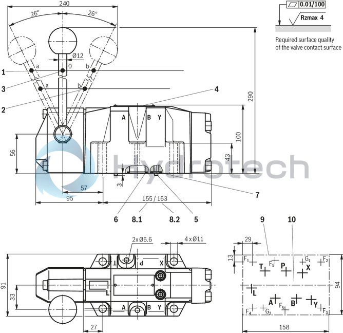
|
1 |
Spool position “a” |
|
2 |
Spool position “b” |
|
3 |
Spool position "0" |
|
4 |
Name plate |
|
5 |
2 locking pins Ø3 |
|
6 |
Identical seal rings for ports A, B, P, and T |
|
7 |
Identical seal rings for ports L, X and Y |
|
8.1 |
Dimension 3 spool position valve |
|
8.2 |
Dimension 2 spool position valve with spring return |
|
9 |
machined valve contact surface |
|
10 |
Porting pattern according to DIN 24340 form A16 and ISO 4401-07-07-0-05 |
Subplates according to data sheet RE 45056
(separate order)
G 172/01 (G3/4)
G 174/01 (G1)
G 174/08 (flange)
Valve mounting screws (separate order)
4 hexagon socket head cap screws
ISO 4762 - M10 x 60 - 10.9-flZn-240h-L
Friction coefficient µtotal = 0.09 to 0.14,
tightening torque MA = 75 Nm,
material no. R913000116
2 hexagon socket head cap screws ISO 4762 - M6 x 60 - 10.9,
friction coefficient µtotal = 0.09 to 0.14,
tightening torque MA = 12.5 Nm
material no. R913000115
|
1 |
Spool position “a” |
|
2 |
Spool position “b” |
|
3 |
Spool position "0" |
|
4 |
Name plate |
|
5 |
2 locking pins Ø6 |
|
6 |
Identical seal rings for ports A, B, P, and T |
|
7 |
Identical seal rings for ports X and Y |
|
9 |
machined valve contact surface |
|
10 |
Porting pattern according to DIN 24340 form A25 and ISO 4401-08-08-0-05 |
Subplates according to data sheet RE 45058, 45059
(separate order)
G 150/01 (G3/4)
G 151/01 (G1)
G 154/01 (G1 1/4)
G 156/01 (G1 1/2)
Valve mounting screws (separate order)
6 hexagon socket head cap screws
ISO 4762 - M12 x 60 - 10.9-flZn-240h-L
Friction coefficient µtotal = 0.09 to 0.14,
tightening torque MA = 130 Nm,
material no. R913000121
Size 32
Dimensions in mm
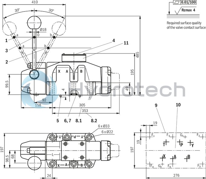
|
1 |
Spool position “a” |
|
2 |
Spool position “b” |
|
3 |
Spool position "0" |
|
4 |
Name plate |
|
5 |
2 locking pins Ø6 |
|
6 |
Identical seal rings for ports A, B, P, and T |
|
7 |
Identical seal rings for ports X and Y |
|
8.1 |
Dimension for 2 and 3 spool position valve with detent and 3 spool position valve with spring return |
|
8.2 |
Dimension 2 spool position valve with spring return |
|
9 |
machined valve contact surface |
|
10 |
Porting pattern according to DIN 24340 form A32 and ISO 4401-10-09-0-05 |
|
11 |
Diversion plate |
Subplates according to data sheet RE 45060
(separate order)
G 157/01 (G1 1/2)
G 157/02 (M48 x 2)
G 158/10 (flange)
Valve mounting screws (separate order)
6 hexagon socket head cap screws
ISO 4762 - M20 x 80 - 10.9-flZn-240h-L
Friction coefficient µtotal = 0.09 to 0.14,
tightening torque MA = 160 Nm,
material no. R901035246
Spool position monitoring
Inductive position switch type QM
Dimensions in mm
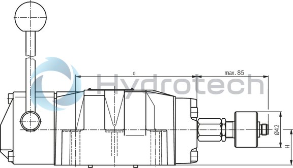
| 1) | For dimensions, see valve dimensions |
Inductive position switch type QM, 4WMM
Dimensions in mm
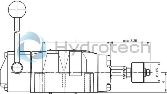
Notice:
The dimensions are nominal dimensions which are subject to tolerances.
|
Size |
16 | 25 | |
|
H |
mm |
34 | 37 |