

BOSCH REXROTH
R900962531
$4,326.34 USD
- BOSCH REXROTH
- Material:R900962531
- Model:ZDRE6VP3-1X/100MG24K4M-1
Quantity in stock: 0
The Bosch Rexroth ZDRE6VP3-1X/100MG24K4M-1 (R900962531) is a sophisticated pilot-operated pressure reducing valve designed for precise control of system pressure through electrical operation. This valve is particularly engineered to manage the reduction and limitation of pressure within hydraulic systems, ensuring stable and reliable performance in various applications. It consists of three main components: the pilot control valve, a proportional solenoid with integrated control electronics, and the main valve that includes the main control spool. The functionality of this valve is based on command value-dependent settings that allow for adjustments in pressure reduction in channel P via the proportional solenoid. The spring mechanism maintains the initial position of the main control spool when depressurized, facilitating an open connection from P to T while blocking P to A. The design ensures fluid flow is appropriately directed through various channels and bores, controlled by a pilot oil flow system. During pressure reduction operations, pilot pressure builds up in response to command values, influencing the movement of the main control spool. This mechanism allows hydraulic fluid to flow from P to A as needed, with actuator pressure being regulated through a series of channels and nozzles. The set pressure at the pilot control valve dictates this process, maintaining near-identical pressures at port P. For pressure limitation functions, if port P's pressure surpasses the set value at the pilot control valve, there is an automatic adjustment as the main control spool shifts to reduce this excess pressure by connecting P to T. This feature safeguards against overpressure situations. This model is suitable for subplate mounting or sandwich plate design according to ISO standards and offers flexibility with minimum set pressures in ports A or P. It also features integrated electronics (OBE), enhancing its ease of use and integration into various hydraulic systems. The ZDRE6VP3-1X/100MG24K4M-1 can handle maximum operating pressures up to a specified limit and accommodates a considerable flow rate measured in liters per minute, making it versatile for demanding applications requiring precise pressure management.
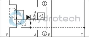
The valves of type ZDRE are electrically pilot-operated 3-way pressure reducing valves with pressure limitation of the actuator. They are used for reducing a system pressure.
Technical set-up:
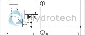
The valve consists of three main assemblies:
Pilot control valve (1) Proportional solenoid (2) Main valve (3) with main control spool (4)Function:
General function:
Command value-dependent setting of the pressure to be reduced in channel P1 via the proportional solenoid (2). In the depressurized port P, the spring (17) holds the main control spool (4) in the initial position. Thus, opening the connection from P1 to T and blocking of the connection from P to P1. Pressure connection from port P to the ring channel (5). Pilot oil flows from the bore (6) to port T, via the flow controller (7), the nozzle (8) to the pilot control valve (1), the throttle gap (9) to the longitudinal groove (10) and the bores (11, 12).Pressure reduction:
Build-up of the pilot pressure in the control chamber (16) as function of the command value. Movement of the main control spool (4) to the right, hydraulic fluid flows from P to P1. Actuator pressure present in port P1 to the spring chamber (15) via channel (13) and nozzle (14). Increase in the pressure in port P1 to the set pressure of the pilot control valve (1) leads to the movement of the main control spool (4) to the left. Pressure in port P1 is almost identical with the set pressure at the pilot control valve (1).Pressure limitation:
If the pressure in port P1 exceeds the set pressure of the pilot control valve (1), the main control spool (4) is moved further to the left. This opens the connection from P1 to T and limits the pressure present in port P1 to the set command value.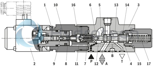
The valves of type ZDREE are electrically pilot-operated 3-way pressure reducing valves with pressure limitation of the actuator. They are used for reducing a system pressure.
Technical set-up:
The valve consists of three main assemblies:
Pilot control valve (1) Proportional solenoid (2) with control electronics (18) Main valve (3) with main control spool (4)Function:
General function:
Command value-dependent setting of the pressure to be reduced in channel P1 via the proportional solenoid (2). In the depressurized port P, the spring (17) holds the main control spool (4) in the initial position. Thus, opening the connection from P1 to T and blocking of the connection from P to P1. Pressure connection from port P to the ring channel (5). Pilot oil flows from the bore (6) to port T, via the flow controller (7), the nozzle (8) to the pilot control valve (1), the throttle gap (9) to the longitudinal groove (10) and the bores (11, 12). Supply and command value voltage or command value current are applied to the connector (19). At the factory, the command value pressure characteristic curve is adjusted with little manufacturing tolerance.Pressure reduction:
Build-up of the pilot pressure in the control chamber (16) as function of the command value. Movement of the main control spool (4) to the right, hydraulic fluid flows from P to P1. Actuator pressure present in port P1 to the spring chamber (15) via channel (13) and nozzle (14). Increase in the pressure in port P1 to the set pressure of the pilot control valve (1) leads to the movement of the main control spool (4) to the left. Pressure in port P1 is almost identical with the set pressure at the pilot control valve (1).Pressure limitation:
If the pressure in port P1 exceeds the set pressure of the pilot control valve (1), the main control spool (4) is moved further to the left. This opens the connection from P1 to T and limits the pressure present in port P1 to the set command value.
|
01 |
02 |
03 |
04 |
05 |
06 |
07 |
08 |
09 |
10 |
11 |
12 |
13 |
14 |
15 |
||
|
Z |
DRE |
6 |
‒ |
1X |
/ |
M |
G24 |
* |
|
01 |
Sandwich plate |
Z |
|
02 |
Proportional pressure reducing valve |
DRE |
|
03 |
For external analog electronics |
no code |
|
With integrated electronics |
E |
|
|
04 |
Size 6 |
6 |
|
Pressure reduction |
||
|
05 |
in channel A (subplate mounting) |
no code |
|
In channel P (sandwich plate valve) |
VP |
|
|
Position of the mating connector (omitted in case of subplate mounting) |
||
|
06 |

|
1 |

|
2 |
|

|
3 |
|

|
4 |
|
|
07 |
Component series 10 ... 19 (10 ... 19: unchanged installation and connection dimensions) |
1X |
|
Pressure rating |
||
|
08 |
50 bar |
50 |
|
100 bar |
100 |
|
|
210 |
||
|
315 bar |
315 1) |
|
|
09 |
Without check valve |
M |
|
Power supply |
||
|
10 |
Direct voltage 24 V |
G24 |
|
11 |
With manual override |
N9 |
|
Without manual override |
no code |
|
|
Electrical connection |
||
|
12 |
For type ZDRE: |
|
|
Without mating connector; connector DIN EN 175301-803 |
K4 |
|
|
For type ZDREE: |
||
|
Without mating connector; connector M12 |
K24 |
|
|
Electrical interface |
||
|
13 |
Command value 0 … 10 V |
A1 |
|
Command value 4 to 20 mA |
F1 |
|
|
For type ZDRE: |
no code |
|
|
Seal material |
||
|
14 |
NBR seals |
M |
|
FKM seals |
V |
|
|
15 |
Further details in the plain text |
* |
For applications outside these parameters, please consult us!
general
|
Type |
ZDRE | ZDREE | |
|
Size |
6 | ||
|
Component series |
1X | ||
|
Installation position |
Any | ||
|
Weight |
kg |
2 | 2.1 |
|
Storage temperature range |
°C |
-20 … +80 | |
|
Ambient temperature range |
°C |
-20 … +70 | |
hydraulic
|
Type |
ZDRE | ZDREE | ||
|
Size |
6 | |||
|
Maximum operating pressure |
bar |
315 | ||
|
Maximum operating pressure |
Port P |
bar |
315 | |
|
Port P1 |
bar |
210 | ||
|
Port P2 |
bar |
315 | ||
|
Port A |
bar |
210 | ||
|
Port B |
bar |
210 | ||
|
Port T |
separate and depressurized to the tank | |||
|
Maximum set pressure in ports P1 and A |
Pressure rating 50 bar |
bar |
50 | |
|
Pressure rating 100 bar |
bar |
100 | ||
|
Pressure rating 210 bar |
bar |
210 | ||
|
Pressure rating 315 bar 1) |
bar |
315 | ||
|
Minimum set pressure 2) |
See characteristic curves | |||
|
Pilot flow |
l/min |
0.65 | ||
|
Maximum flow |
l/min |
30 | ||
|
Hydraulic fluid |
see table | |||
|
Hydraulic fluid temperature range |
°C |
-20 … +80 | ||
|
Viscosity range |
mm²/s |
15 … 380 | ||
|
Maximum admissible degree of contamination of the hydraulic fluid, cleanliness class according to ISO 4406 (c) 3) |
Class 20/18/15 according to ISO 4406 (c) | |||
|
Hysteresis 4) |
% |
± 2.5 | ||
|
Repetition accuracy 4) |
% |
< ± 2 | ||
|
Linearity 4) |
% |
± 3.5 | ||
|
Manufacturing tolerance of the command value pressure characteristic curve 5) |
% |
± 2 | ± 3 | |
|
Step response 6) |
10 ... 90% |
ms |
≈ 150 | |
|
90 ... 10% |
ms |
≈ 150 | ||
| 1) | Only available for "Z" version |
| 2) | with command value 0 in channels P1 and A |
| 3) | The cleanliness classes specified for the components must be adhered to in hydraulic systems. Effective filtration prevents faults and simultaneously increases the life cycle of the components. For the selection of the filters, see www.boschrexroth.com/filter. |
| 4) | Of the maximum set pressure |
| 5) | of the maximum set pressure, related to the hysteresis characteristic curve, pressure increasing |
| 6) | measured with 1 liter standing hydraulic fluid column |
|
Hydraulic fluid |
Classification |
Suitable sealing materials |
Standards |
|
Mineral oils and related hydrocarbons |
HL, HLP |
NBR / FKM |
DIN 51524 |
|
Bio-degradable - insoluble in water |
HETG |
NBR / FKM |
VDMA 24568 |
|
HEES |
FKM |
||
|
Bio-degradable - soluble in water |
HEPG |
FKM |
VDMA 24568 |
|
Flame-resistant - water-free |
HFDU, HFDR |
FKM |
ISO 12922 |
|
Flame-resistant - containing water |
HFC (Fuchs HYDROTHERM 46M, Petrofer Ultra Safe 620) |
NBR |
ISO 12922 |
|
Important information on hydraulic fluids: For more information and data on the use of other hydraulic fluids please contact us. The flash point of the process and operating medium used must be 40 K over the maximum solenoid surface temperature. There may be limitations regarding the technical valve data (temperature, pressure range, life cycle, maintenance intervals, etc.). |
Flame-resistant - containing water Maximum operating pressure of 210 bar Maximum hydraulic fluid temperature 60 °C Expected life cycle as compared to HLP hydraulic oil 30% to 100% |
||
electrical
|
Type |
ZDRE | ZDREE | ||
|
Voltage type |
Direct voltage | |||
|
Power supply |
Nominal voltage |
24 V | 24 VDC | |
|
Lower limit value |
VDC |
18 | ||
|
Upper limit value |
VDC |
35 | ||
|
Minimum control current |
mA |
100 | ||
|
Maximum control current |
mA |
1600 | ||
|
Solenoid coil resistance |
Cold value at 20 °C |
Ω |
5 | |
|
Solenoid coil resistance |
Maximum hot value |
Ω |
7.5 | |
|
Duty cycle |
% |
100 | ||
|
Current consumption |
A |
1.5 | ||
|
Required fuse protection |
2 A, time-lag | |||
|
Inputs |
Voltage |
V |
0 … 10 | |
|
Current |
mA |
4 … 20 | ||
|
Outlet |
Actual current value |
1 mV ≙ 1 mA | ||
|
Protection class according to DIN EN 60529 |
IP65 (with mating connector mounted and locked) | |||
|
Conformity |
EN 61000-6-2: 2011-06, EN 61000-6-3: 2011-09 | |||
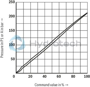
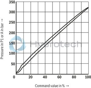
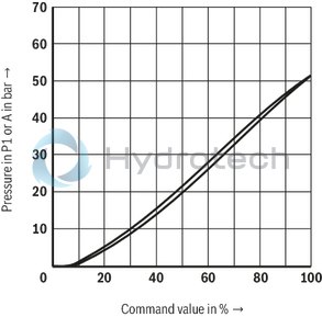
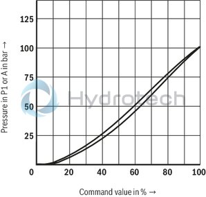
(measured with HLP46, ϑOil = 40 ±5 °C)
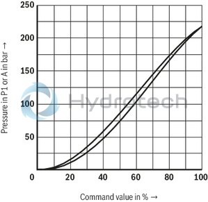
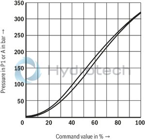
Pressure in port A dependent on the command value (manufacturing tolerance); without flow
(Z)DRE
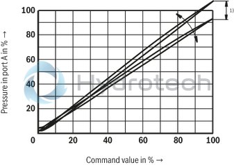
| 1) | With type (Z)DRE, the manufacturing tolerance at the external amplifier can be adjusted using the command value attenuator potentiometer "Gw". With the digital amplifier, the setting is made using the "Limit" parameter. In this connection, the control current according to the technical data must not be exceeded! In order to match several valves to the same characteristic curve, at a command value of 100%, the pressure must not exceed the maximum set pressure of the relevant pressure rating at no valve. |
Type (Z)DRE: Pressure in port P1 or A dependent on the command value
Pressure rating 50 bar
(Z)DRE
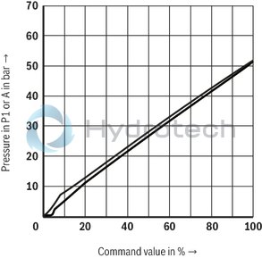
Pressure rating 100 bar
(Z)DRE
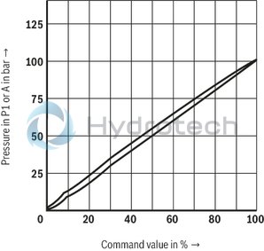
Pressure rating 210 bar
(Z)DRE
Pressure rating 315 bar
ZDRE
Pressure rating 50 bar
(Z)DREE
Pressure rating 100 bar
(Z)DREE
Pressure rating 210 bar
(Z)DREE
Pressure rating 315 bar
ZDREE
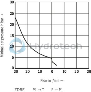
Minimum set pressure in port P1 or A with command value 0 V
(without counter pressure in channel T)
Pressure rating 50 bar
(Z)DRE
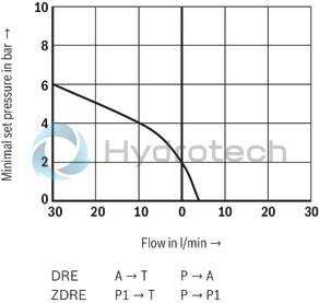
Pressure rating 100 bar / 210 bar
(Z)DRE
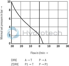
Pressure rating 315 bar
ZDRE
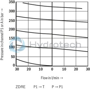
Pressure in channel P1 or A – flow
Pressure rating 50 bar
(Z)DRE
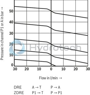
Pressure rating 100 bar
(Z)DRE
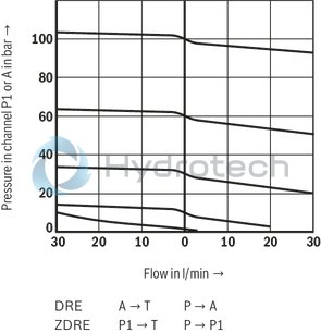
Pressure rating 210 bar
(Z)DRE
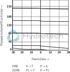
Pressure rating 315 bar
ZDRE
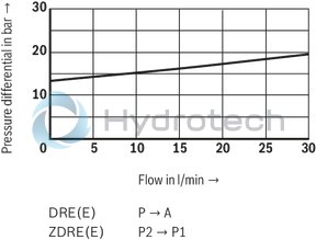
Δp-qV characteristic curves
(Z)DRE
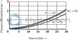
Δp-qV characteristic curves
(Z)DRE
Notice:
The indicated Δp value corresponds to the minimum pressure available in port P (P2) minus the maximum pressure to be controlled in port A (P1).
Type ZDRE 6 VP...
Type ZDREE 6 VP...
(Z)DREE 6...1X
|
Pin assignment |
Contact |
Assignment interface "A1" |
Assignment interface "F1" |
|
Power supply |
1 |
24VDC(u(t)= 21 ...35V);Imax ≤ 1,5 A |
|
|
Command value input |
2 |
0 ... 10 V; Re = 20 kΩ |
4 ... 20 mA; Re = 100 kΩ |
|
Reference potential actual value |
3 |
0 V |
|
|
Differential amplifier input (command value) |
4 |
Reference potential command value |
|
M12 plug-in connector port
Connector on amplifier

Mating connector and wire colors with pre-assembled cable set
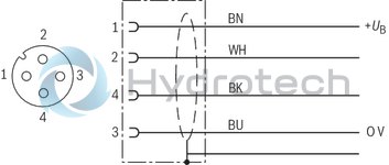
Connection at the connector

Connection at mating connector

Connection cable
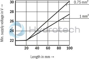
| 1) | Connection cable:- Recommendation 6-wire, 0.75 or 1mm2 plus protective earthing conductor and screening- Connect screening to PE on supply side only- Maximum admissible length 100 m The minimum supply voltage at the power supply unit depends on the length of the supply line (see diagram) |
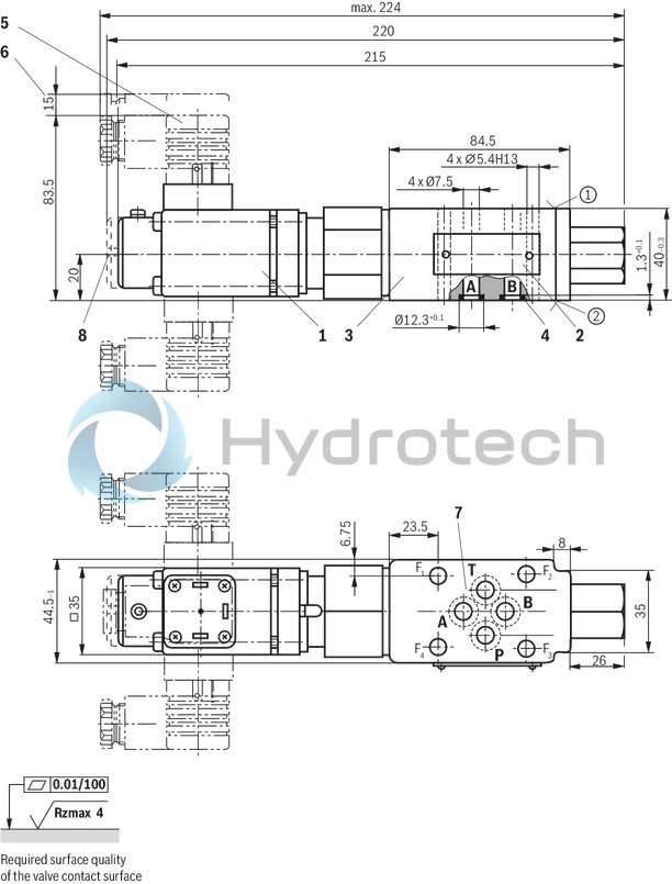
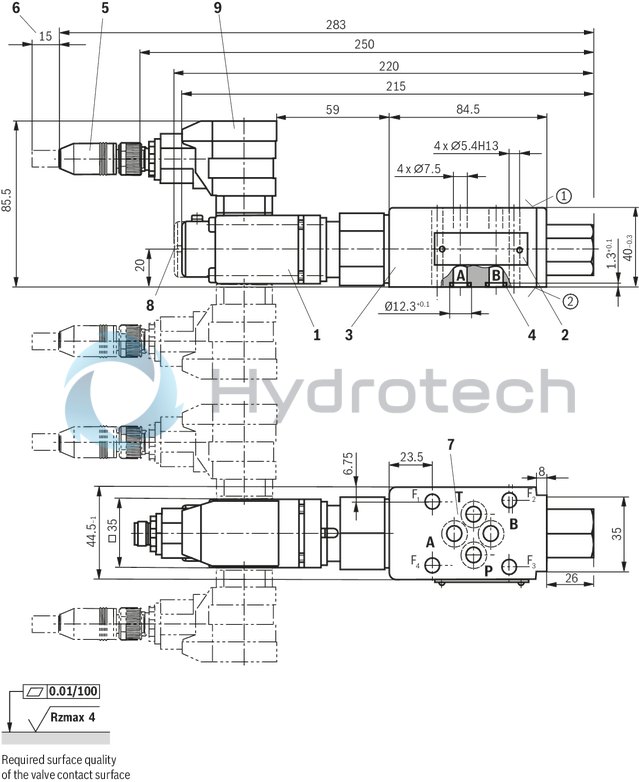
Type ZDRE
Dimensions in mm
|
1 |
Proportional solenoid without manual override |
|
2 |
Name plate |
|
3 |
Valve housing |
|
4 |
Identical seal rings for ports A, B, P, and T |
|
5 |
mating connector according to DIN EN 175301-803 |
|
6 |
Space required to remove the mating connector |
|
7 |
Machined valve contact surface; Porting pattern according to ISO 4401-03-02-0-05 |
|
8 |
Proportional solenoid with manual override |
Type ZDREE
Dimensions in mm
|
1 |
Proportional solenoid without manual override |
|
2 |
Name plate |
|
3 |
Valve housing |
|
4 |
Identical seal rings for ports A, B, P, and T |
|
5 |
mating connector according to DIN EN 175301-803 |
|
6 |
Space required to remove the mating connector |
|
7 |
Machined valve contact surface; Porting pattern according to ISO 4401-03-02-0-05 |
|
8 |
Proportional solenoid with manual override |
|
9 |
Integrated electronics (OBE) |
Notice:
The dimensions are nominal dimensions which are subject to tolerances.
Recommended valve mounting screws (separate order):
4 hexagon socket head cap screws ISO 4762 - M5 - 10.9-flZn-240h-LTightening torque MA = 7 Nm ± 10%
Mating connectors for valves with connector “K4”, without circuitry, standard
3P Z4
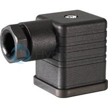
Mating connectors for valves with connector “K4”, without circuitry, standard
3P Z4
For valves with connector “K4” according to EN 175301-803 and ISO 4400, 2-pole + PE, “large cubic connector” Mating connectors for valves with one or two solenoids (individual connection)Data sheet
Spare parts & repair